 
     |
| Picture Post: Fiero Suspension Arm Dimensional Gages I Designed For Pontiac / Entech (Page 1/5) |

|
CampyBob
|
FEB 18, 07:51 PM
|
|
Folks, I'm the guy that designed the Fiero Suspension Arm dimensional gages back in the day. The company I worked for...and still work for (40 years this May)...built the gages.
Pontiac used Teledyne Monarch in Hartville, Ohio to stamp out the suspension arm parts. And yes, it's true, our early Fiero control arms were derived, originally, from a Chevette lower control arm.
GM was throwing tons of money at trying to produce dimensionally correct suspension arms. No amount of booze, fine dining, strippers, corporate jet flights with donuts and coffee waiting was ever enough. I think I was the most pampered young design engineer in North America!
I had already been admiring the then new Fiero from when I saw the prototypes at the also then new Corvette plant in Bowling Green, Kentucky. After starting the gaging project I went out and bought a brand new 1985 2M4, which I still have. You can see pictures of it in the "Sat For 20 Years" post I put up in the technical questions sub-forum.
Ask me any questions and I'll try to answer them as best I can, but remember this was back in the days of DOS and when the Pharaoh and I went to school together.
I will scan some of the old Polaroid prints and edit this post to add more pics as I get them ready to post.
Regards, CampyBob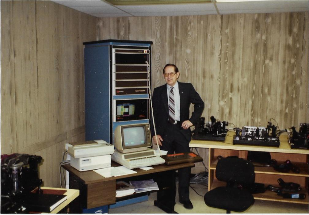 [This message has been edited by CampyBob (edited 02-19-2020).]
|
|

|
Raydar
|
FEB 18, 07:55 PM
|
|
| quote | Originally posted by CampyBob:
...
Gm was throwing tons of money at trying produce dimensionally correct suspension arms. No amount of booze, fine dining, strippers, corporate jet flights with donuts and coffee waiting was ever enough. I think I was the most pampered young design engineer in North America!
|
|
Hahahahahaha!!
I have zero difficulty believing this. 
Welcome to our little corner of the world.
|
|
|
|
Thunderstruck GT
|
FEB 18, 07:55 PM
|
|
Very cool!
I have an original blueprint that may have been used for those gages.
Give me a bit and I'll see if I can get a good picture.
|
|
|
|
CampyBob
|
FEB 18, 08:05 PM
|
|
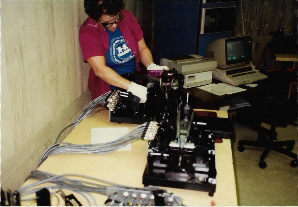
First pic in the above post is of my old boss and company owner, now deceased. RH arms went on the gages to the right of the readout tower and LH arms went on the gages located to the left side of the tower.
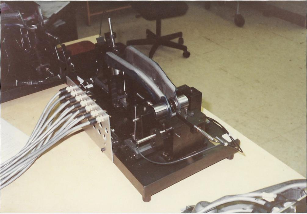
Below, the lowly Chevette control arm. It would get more stamping added to it to become a weldment with two chassis pickup points. Note the use of LVDT's (linear variable displacement transducer) for dimensional input to the Daytronics electronic gaging unit, which is driven by an oh-so-powerful 386 DOS computer. Reports were printed on that Epson FX80 printer.
|
|
|
|
CampyBob
|
FEB 18, 08:12 PM
|
|
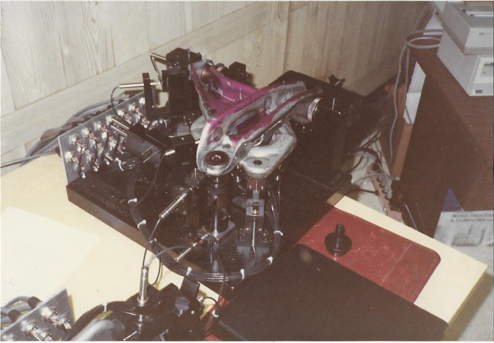
Three stampings are banged out on the presses...the Chevette arm, the 'Y' arm and a coil spring seat. The three are welded into one assembly on precision welding jigs / fixtures. Then samples were gathered and brought to the metrology lab to be measured.
Notice this assembly is 'blued' up with purple DyKem layout dye.
|
|
|
|
CampyBob
|
FEB 18, 08:20 PM
|
|
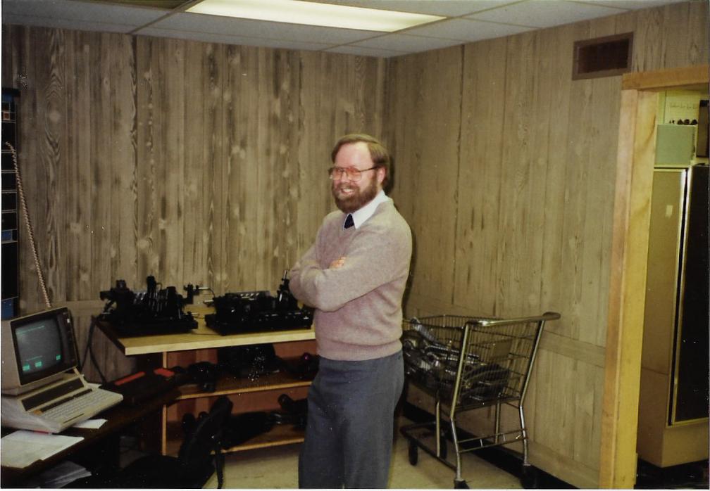
One of the project engineers posing with the tooling. Everyone was proud of this halo project. Hell, the bazillion gallons of jet fuel we burned up on those corporate flights to Pontiac, Michigan's GM-owned 'Big Beaver' airport alone was reason to be proud. A few of those flights back to Akron's Fulton airport was full of blotto engineers too buzzed to even puke.
Note the shopping cart in the pic. The gage technician used the cart to go round up sample parts from out in the press room to bring them back for measuring. Not so high tech, but I guess we spent that part of the budget tipping the strippers.
 [This message has been edited by CampyBob (edited 02-19-2020).]
|
|
|
|
mptighe
|
FEB 18, 08:23 PM
|
|
|
This is awesome, what a great addition for the forum. Thanks for your work, and for sharing.
|
|
|
|
CampyBob
|
FEB 18, 08:24 PM
|
|
A gage technician from Teledyne Monarch loads a suspension arm into the gage and gets it prepared for taking dimensions.
|
|
|
|
RCR
|
FEB 18, 08:26 PM
|
|
Thanx Bob. Great stuff. And welcome to the forum.
Bob------------------

My Build
|
|
|
|
CampyBob
|
FEB 18, 08:39 PM
|
|
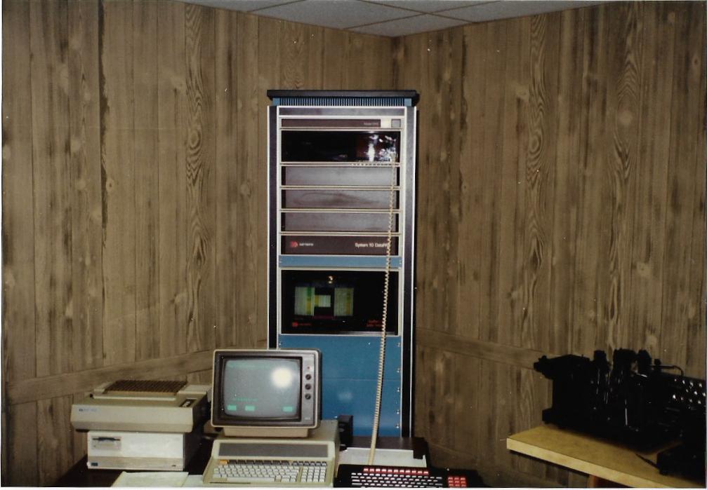
The Daytronics tower contained the LVDT signal conditioning units and an advanced...for that time...color display readout. Note the monochrome CRT monitor on the 386 computer that is also more typical of that era.
The color readout gave the gage operators a quick analysis of whether the part being measured was 'good', 'close enough!' or 'scrap' by scanning the color on the readout.
The readout numbers were expressed as plus or minus from a nominal point in space established by a precision setmaster. We could also switch to an absolute value. The background color behind those readout numbers was: Green = Within part blueprint tolerance. Yellow = Within part control limits...as in women's underwear = diesel fitter. Close enough to ship to Michigan and pray it bolted onto the chassis pickup points. Red = This is a steaming pile o crap. Shred it.
The printer then generated what we were told was boxcar loads of data that got set to Pontiac where it was either burned to keep people warm or hide the evidence. One or the other. No one ever looked at the rain forest we cut down to generate those reports.
 [This message has been edited by CampyBob (edited 02-19-2020).]
|
|
|
