
 
     |
| Saturn Vue EPS install in a 1986 Fiero GT - Warning! - many pictures! (Page 1/3) |

|
AL68
|
APR 05, 09:07 PM
|
|
This is how I installed a Saturn Vue EPS in my 1986 Fiero GT w/auto trans.
.
It may work on manual trans cars but the motor will sit a little lower & you have to remove the clutch starter switch
brackets from the pedal assembly and fabricate a new switch mount (or bypass switch). I have included a few pics
of the manual trans pedal clearance but did not do much with it - I have no driveable manual cars.
Installing the Vue power unit keeps the column and u-joint shaft from being collapsable - no way around it due to modifications
needed to connect power unit to column.
Let me know if you have any ideas on how to do something better/easier! (especially the column center shaft)
---------------------------------------------------------------------
PARTS NEEDED:
Vue column and u-joint shaft
Fiero column and u-joint shaft
4x5" 8ga / .165" steel plate for column bracket
Piece of pipe to make a 6" long/1.84"OD/1.70"ID sleeve
(think I used a 12" piece of 1.5" galvenized water pipe)
Ebay steering controller from seller "brunolopesantunes"
http://www.ebay.com/itm/Sat...x-EPAS-/171027023129
1" x 4" x 1/8" steel/aluminum plate for the box wire cover
steering shaft coupler - I used a Borgeson #314900, 3/4" "DD"x 3/4" round, 1.25 OD x 2" long
small fuse holder for 10a fuse (ignition power for the control box)
heavy (4ga?) wire at least as the size as the Vue motor power wire to go through the console back to the battery
a fuse holder for the power wire - original Vue unit or aftermarket - 80a is the original fuse size
(Walmart has stereo amp install kits with heavy wire and MAXI fuse holders)
a brass stud mount that replaces the positive battery cable bolt like NAPA # 728221
misc parts: 3 nuts for the 6mm Vue tube bolts, solder, heat shrink tubing, wire & ties, terminals,etc.
(read through install first - I might have missed some little stuff needed)
======================================================================================================
SOME TOOLS NEEDED:
mertic sockets/wrenches
(3) needle nose vise grips
soldering iron
drill and 15/64" bit(holes for the 6mm bolts
die grinder & assortment of carbide bits to remove metal at end of column
die grinder with 3" cutoff wheel - something to cut plate steel, shafts, separate Vue column, etc.
special tools:
snap ring pliers
welder
metal lathe to make the metal sleeve, center punch and turn the hole in the adapter plate
lock plate compresser for shaft snap ring
pivot pin puller, Oreily/autozone has under $10, $6 on Ebay shipped - KD Tools #3906D
======================================================================================
A lot of the info on the install came from a thread on The Vintage Mustang Forum,
http://forums.vintage-musta...00-mod-ever-eps.html
Page #7 / post #97 has a lot of info. You have to join to view it.
=======================================================================================
column that can be used: Saturn Vue - from 2002 to 2007 (what I used)
Chevrolet Equinox - from 2005 to 2007
Pontiac Torrent 2005-2007, not 2008
Saturn Ion - from 2003 to 2006
IMPORTANT! The box on the column MUST have a metal lid, not black plastic!
The black ones will not work with the Ebay controller.
The steering wheel, column switches and lock cylinder are not needed.
Get the u-joint shaft to the rack and the two plugs for the column module, 8" for the
purple/pink wire plug, 12" for the power plug, unbolt the ground wire from the brake bracket.
Also get the 80A fuse/holder for the power wire(under the brake booster on the Vue,
unknown for the others - follow the power wire out the dash) if you don't have a fuse
setup (about $12 at Walmart)

First, remove the steering wheel using a puller. If a puller is not available you
may get it loose by putting the nut back on the shaft a few threads, hold the column
upright off the ground & have someone else hit nut/end of shaft with a hammer.
The threaded column end & any wires for the wheel will not be used.


Remove the bolts for the lock cylinder & slide off the switch assembly.
The column and parts used wil look like this:

remove snap ring at top of column shaft and 3 10mm bolts at bottom of tube

slide tube off shaft

pull upper shaft off box splined shaft (pull hard) - will use later

cut upper tube/first layer at red line to separate lower tube. Keep lower tube
with 3-bolt flange, upper section is not needed.


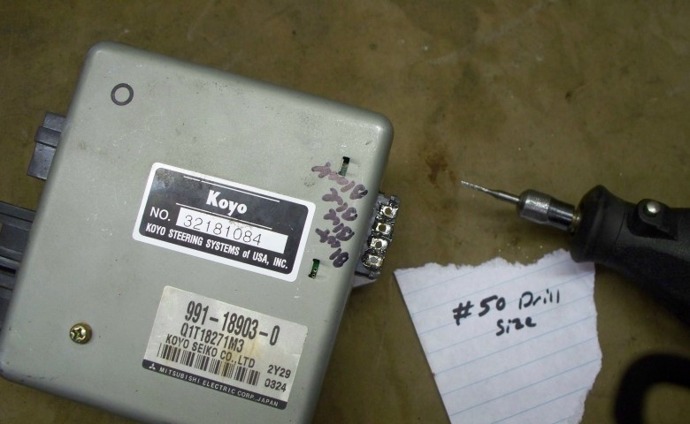
Now we need to remove the module from the motor - remove the side cover, pull
the wires out slightly and remove the black plastic piece behind the white plugs.


Mark the wire/plug locations: red plug on left (to lower sensor), white plug on right (to upper sensor)
wires:black/blue/blue/black
unsolder the plugs from the module - heat one pin & rock plug to the side to pull it out a little,
then heat the other pin & rock the other way - repeat until each plug is loose.
OR
You could just mark & cut the wires(don't un-solder the plugs) & solder/heat shrink new longer wires on

remove the two 5mm allen bolts and remove module.
pull out the black seal & clean off the gease - going to seal this area with tape while grinding

I used a #50 drill bit to clean out the module's holes to solder in new wires
Tape up the input, output and module wire holes for grinding off the Vue brackets: One mount will
hit the brake light switch, the other will hit the brake pedal bracket.
Knock out the sleeve with a punch, cut off the sleeve's mounts with a hack saw or your 3" cut-off
wheel. Grind off everything marked in black.


The box will look like this when done, just the ears for the bolts left

You also need to grind open the slot at the red arrow for the wires:

Now you need to rotate front plate so wires are facing up - unbolt the two gold bolts, lift
the plate up enough to clear the motor & rotate 180 degrees and bolt back down.


cut the wires short & solder/heat shrink each one to a different color wire about 12"long - make
sure you write down which wire goes to each color: red plug-black or blue, white plug-black or blue
What I did: (top sensor, white plug) black to black, blue to blue
(bottom sensor, red plug) black to brown, blue to light blue

make a plate from 1/8"x 1" aluminum to cover the hole and wires - the box is done!
 [This message has been edited by AL68 (edited 04-06-2015).]
|
|
|
|
AL68
|
APR 05, 09:12 PM
|
|
Now you need to remove the column from the car. I forgot to take pics & can't find any posts
showing removal:
1) disconnect battery
2) remove trim plate under column (four 7mm screws)
3) at base of column remove 11mm pinch bolt on upper u-joint
4) remove the two 15mm bolts at the top column mount bracket
5) loosen & remove the two 15mm nuts at the bottom column mount bracket - the column will start to drop
6) unplug the connectors for turn signals, dimmer switch, wiper switch and cruise control if equipped.
7) the shift interlock cable end is attached to the ignition switch with 2 small phillips screws - remove them
to disconnect the cable.
The Ogre's Cave has a shifter article to re-align cable when assembling, about half way through the article:
http://home.comcast.net/~fierocave/shift_auto.htm
(If you keep the shifter in park, do not remove the ignition switch from the side of column and have
the key in the lock position when removing and installing it should line back up ok.)
8) should be able to pull the column out now but it might hang up on the u-joint - you may have to tap
a screwdriver into the u-joint's pinch bolt slot to expand the joint a little to remove the column
9) remove the u-joint shaft from the rack: Jack up and support car on jack stands, pull back plastic boot,
remove joint pinch bolt & slide joint off of rack. From inside car pull shaft out of boot.
(alternate way: remove the spare tire tub. More work but you don't have to jack up car & there's more
room to get to the rack joint.)
|
|
|
|
AL68
|
APR 05, 09:18 PM
|
|
Column disassembly.
You might want to read these threads I found on columns, LOTS of info on
teardown and re-assembly, shows some details I might have left out:
http://www.fieros.de/en/articles/steering.html
http://www.fiero.nl/forum/F...L/088020-3.html#p111 (pictures about half way down)
http://www.crankshaftcoalit...ing_Rack_Rebuild.pdf (saveable PDF file of the above thread)
First remove the lockplate plastic cover, emergency flasher knob and lockplate retainer clip as shown in pic.
clip is fun to remove, use picks, small screwdrivers, etc. to pop it out of the groove & slide up shaft - don't
spread it apart too far.

remove the lockplate, cancel cam,spring,spring cup and upper bearing race

remove the top column mount bracket (mark the front) and plastic wire guide.

remove the screw for the turn signal lever and 3 screws for the turn signal switch, pull the switch wires out
of the housing


remove remove the key chime contacts&spring (will probably separate,put together like pic),
the lock cylinder bolt and lock cylinder and 3 upper bowl torx screws


pull upper bowl off & wiper switch wires (and cruise switch wires if equipped) through hole as an assembly
REMEMBER HOW THE WIRES COME THROUGH THE UPPER BOWL & GO THROUGH THE LOWER BOWL - I think the cruise wire
is routed through the left side of the column, not down the hole with the wiper/turn signal wires.


unscrew the tilt lever - may have loctite on it & turn hard. remove the side cover and dimmer switch cam


using a Phillips screw driver press the spring retainer down then rotate counter clockwise to release spring parts


(Continued next post)
|
|
|
|
AL68
|
APR 05, 09:22 PM
|
|
next pull the tilt pivot pins using special tool, the first of the other post shows using a screw and vise grips,
I've never been able to get them out that way - always too tight. O'Reily and Autozone have them for $10,
also on Ebay KD Tools 3906D for $6 shipped.


screw back in the tilt lever & pull foreward to disengage the lock cams, lift the lower bowl up and foreward,
pulling assembly off column. note dimmer switch rod position through hole
rack lever goes in rod slot when puting back together


on bottom of column remove lock ring (break), spring and lower bearing parts - none of the parts will be re-used

pull shaft out top of column, turn upper joint 90 degrees to separate joint


remove the 4 torx bolts and the lower mount noting the position of the dimmer switch rod to switch &
how it fits in lower mount hole

remove the lower plate - slide sideways and turn up, then pull up the lower bowl


column is nearly bare, you don't have to remove anything else for the modifications
|
|
|
|
AL68
|
APR 05, 09:27 PM
|
|
BRAKE PEDAL BRACKET MOD - automatic trans
BEFORE the column mods you need to modify the brake pedal bracket to clear the motor.
This can be done in car - cut at the red line in the picture.
(bracket is manual trans but cut is same)
DO THIS IF POSSIBLE - bracket does not like to come out or go back in easy because of tight
clearances to a wiring harness. Don't say I didn't warn you! 
Also, for a little extra clerance to the steering u-joint, take a crescent wrench and bend the
brake bracket a little to the driver side (1/8-1/4") where it's marked in white in the picture.
My second install had about 1/4" clearance at the point without bending it, a little more wouldn't
hurt.


If you want to remove the pedal assembly to modify it's a little hard to get it out past the large
wire harness in front of it.

First remove the 4 power booster nuts, the power booster rod to the pedal, switch connectors and one nut
straight up on the bracket. Try sliding a wide putty knife between the wire bundle and the
bracket and pull the pedal bracket back towards seat and down. The bracket will not want to come out
easy because of the wires - don't damage them!

cut the bracket at the red line in the previous picture, also cut a little off the top mount at the black
marked area in the next picture to help put the bracket back in. Round the edges of the metal to keep
from damaging the wire & use the putty knife to help slide in. May not go back in easy, might have to
push wire bundle around to get back in.

Bolt bracket and booster back in - Bracket mod is done.
--------------------------------------------------------------------------------------------------------
FOR MANUAL TRANS ONLY: I did fit the column in a manual trans car but there are some additional problems:
1) the brackets in the next pic for the starter switch had to be removed. You will
have to make something to replace the clutch pedal starter switch (or bypass it).
Cut brackets at the red/white marks in the next picture

pedals mounted

2) motor mounts flat instead of angled up behind the fuse panel so clutch pedal
will not hit motor, may have foot clearance problem. With a 9 1/2 shoe & my heel
on the floor under the motor the tip of my shoe will touch the motor.

3) fuse block will have to be moved a little, won't fold up - hits motor end.
4) the motor control box may not mount on the motor like the automatic setup,
may have to mount remotely - not a big problem
normal automatic angled mounting - plenty of foot clearance but clutch pedal will not come back up all the way

Mounting the motor to the column will be the same just the bracket holes will be in a different location
on the plate.
You will have to figure out the problems listed above for the clutch pedal setup, I don't
have a running manual trans car I need to make a column for.
|
|
|
|
AL68
|
APR 05, 09:47 PM
|
|
COLUMN MOD
First you need to cut the bracket at the lower end of the column to weld on a plate to bolt the motor to.
Cut at the white lines in the picture on both sides so the column lower mounting bracket is slightly
(a few thousandsof an inch) behind the end of the round tube but DO NOT REMOVE METAL FROM THE ROUND TUBE END, you want
a flat surface to weld the plate to. The cuts don't have to be perfect, the plate will be touching the
tube end when welded on. Don't remove the the area at the red arrow, this will be used to align the
motor mounting plate.


The end of column should now look like next picture. File flat the top of the mounting areas marked in red.
File flat/square off the areas marked in yellow - will be the alignment spot for the mounting plate.
Also file the tabs at a slight taper outward to slide the plate off the end of the tube.

Take the 4 x 4.5" plate and make two notches about 1/16" deep to fit the plate tight between the
two mounting tabs. It should sit flat on the end of the round tube & not touch the mounting bracket
except at the notched alignment points, the alignment points should not raise the plate up off the round
tube - THE PLATE MUST SIT FLAT ON END OF THE TUBE.
The steel plate should sit flat like picture with cardboard plate (forgot to take picture of steel one).


##############################################################################################################
I put this part in the wrong order, you need to shorten the column before test fitting for the motor clock position and welding the plate on.
(I made 2 column up at the same time & welded the 2nd before collapsing it)
Lay the plate on the end of the column, measure down the same 4 1/8" & tap column together to this mark.
this is the part from the end of the tube build that should be done now:
The column is too long to fit as-is, need to collapse it a little to fit. It needs to be 4 1/8" from the welded
on plate to the bottom of the upper tube, it should be about 5.25 now. Mark the lower tube so you don't go too far.
Place column tube top on a small wood block with the ignition switch rod off to the side. Put another wood block
on the motor mounting plate & CAREFULLY tap the column together until you reach the 4 1/8" mark.


Now continue modifying the tube and making the plate as before below:
#######################################################################################
next you need to make the inside of the tube end completely round inside: use a die grinder and carbide
bit to remove the tabs for the lower bearing screws & any raised spot welds from the lower mounting bracket
you can feel inside the tube for about 4" inside the tube.

Now we need to use the Vue upper tube to make the bolt pattern on the steel plate to mount the box. The
tube has a smaller outside diameter than the Fiero column tube inside diameter. I made a 4" long sleeve out
out of a piece of water pipe. My mesurements were 1.840" OD / 1.700" ID BUT it fit a little loose on the second
column tube I built. Make your own measurements after grinding out the column tube for the best fit.
While you have access to a lathe make a small center punch with a tiny center tip to fit tight into the 3 holes
of the Vue tube with the 3 mounting tabs, you will need it to mark holes to drill in the mounting plate.
Another idea I had (but have not tried) to avoid making the sleeve - wrap the Vue tube evenly with a wide tape
(masking, duct tape, etc.) where the sleeve is in the picture to build up it's outside diameter
until it fits snug into the Fiero column but it must be able to rotate a little. This should center the Vue tube
almost as good as a metal sleeve.


Bolt the Vue tube back on the PS unit with a bolt in either of the two red arrow spots (other spot may keep box
from rotating on Fiero column while aligning) and slide the sleeve (or tape up the tube) onto the tube.

Bolt the upper bracket back on the Fiero column in the original direction, then slide the Fiero column onto the Vue
tube/sleeve assembly with the motor pointing to the left. The column should look like this now except the motor
nose & wires should be facing down, I didn't rotate the motor end yet.

the little square notch outlined in white on the bottom of the Fiero column is going to be the alignment point for
the motor.

Install column/motor assembly in car with the original 2 bolts/2 nuts. The electric motor should
angle behind fuse block like the following picture. You can get more clearance by folding down
to fuse block, press in the release tabs on the sides.

Rotate the motor to about the 10:00 position and place a mark at the square notch at the bottom of the Fiero column
like in the picture (mark the Vue tube, not the sleeve). This will give the best clearance up and down, any higher the
original control box will hit the cowl when mounted to the motor in a future step.
(You may want to mount the control box to the motor now with wire ties to test fit, see the pictures farther down. It is a tight fit to the cowl &
you can't change the plate once welded on)
The mark should line up(or almost line up) with the spot where the tab for bolting on the Vue tube meets the round part of the motor (green arrow).

Remove column assembly from car & unbolt the Vue tube from the box. Slide the Vue tube & sleeve into the column end,
aligning the mark you made with the notch at the column bottom.

Now take the 4x5 steel plate you notched earlier, place on end of aligned tube, notches on the bracket.


Using 3 needle nose vise-grips clamp the 3 Vue tube tabs to the plate TIGHT!

Once secure, pull the plate and tube assembly out of the column end.
Put marks on the plate and Vue tube so you can bolt the plate onto the tube in the same position.

Now you need to mark the hole centers to drill the mounting plate holes.
I made a small/shallow tip center punch to barely go into the Vue tube mounting ears & mark the holes.

drill the three holes 15/64, cut the Vue tube to the same size as the sleeve.

Lightly bolt the plate on the Vue tube in the same position, put on the sleeve & slide assembly back into
the column end. The bolts will hit the column end in a couple places, use a die grinder with a carbide bit
to grind away part of the lower column bracket to clear so Vue tube & plate will sit flat on column tube end.

(continued in next post)[This message has been edited by AL68 (edited 04-12-2015).]
|
|
|
|
AL68
|
APR 05, 09:53 PM
|
|
once column end is clearanced for bolts, align mark with slot on bottom & the plate notches with the lower
mount tabs. Now use the die grinder to clearance the bolts so a wrench will fit on the head & the bolt can be
unscrewed (you can slide out tube/plate to grind)
TIP: find 3 bolts same thread/length but with 8mm head, less grinding needed. See previous picture of
aluminum plate wire cover for the Vue steering box for bolt pic.

You will end up with something like these pics, continue slots higher to have room to unscrew bolts (red "X" area) :


Thghten the 3 plate bolts, trace around tube tabs and lower column for bracket final shape, keep about 1/16" of
the lower plate notch over the top of the lower column to align plate.

Now remove plate from Vue tube & cut to look like 2nd picture, curve top point - it points down in car.
(center hole in next step)


Lightly bolt the plate onto the Vue tube, put the sleeve back on and slide assembly back into tube.
Line up the lower plate notches & press the plate snugly against the column tube. Tighten all
three bolts TIGHT to keep plate aligned on tube. Put the tube in lathe with plate on end, drill/turn
a hole in the plate to match the diameter of the Vue box at the red arrow, then make a large chamfer
on the hole to clear the box at the green arrow so the plate will sit flat on the box.
(you can shorten the tube more to fit in the lathe, it will not be used for anything else)


Test fit bracket on column end, make sure chamfer is facing out & it SITS FLAT ON THE COLUMN TUBE
so it will weld on flat.
You also need to clean the paint off for welding. I bead blasted the column end. Mark the switches position
with a permanant marker - circle the bolt positions, draw lines where they overlap, etc.(they are adjustable)
blow off column well afterwards. A wire wheel and/or paint stripper could work also.

Need to extend/close the slots in the lower mount, I used a couple fender shims the same thickness as the
mount & cut to fit.

Time to weld! Put the bracket on the end of the column & line up with the lower plate notches, chamfer out.
I ran a long piece of 3/8" threaded rod through the column with a piece of 1"x3"x1/8" steel with a hole in
the center & nut on each end to pull the bracket tight to the column tube.
Tack weld the plate to the column in a few places to keep it from warping, then weld the plate to the center
tube and lower bracket wherever possible: around tube, both sides of the lower column bracket. Also weld on
the end pieces for the lower bracket slots.
The column end should look like the next pics when done, you may have grind away a little of the welds so
the 3 bolts will tighten down flat. Grind the mounting bracket slots flat where the end pieces were welded on.
Bolt the column back on the box & check clearances for bolts, grind where necessary.


You can now paint the column, Krylon satin black works good.
column body is done[This message has been edited by AL68 (edited 04-12-2015).]
|
|
|
|
AL68
|
APR 05, 10:03 PM
|
|
Column center shaft - LOOKING FOR IDEAS TO MAKE EASIER/BETTER
There are a couple ways of doing the center shaft, each with advantages/disadvantages:
1: This is the way I did the first one, same as the Mustang board. Works fine but you have to bore out
the lower die-cast bowl center from about 1.25" to almost 1.5" to clear the large center joint
when installing the center shaft. The shaft length is 8.5" as shown in picture after welding together.
Length measurments are not critical, overall length is set with the Fiero upper shaft length when
welding together.
You need the Vue upper column shaft & the Borgeson #314900 steering coupler, cut the Vue shaft off 5" from the
bottom. The large ID of the Vue shaft is about 1.215", you will have to turn the 1.25" OD coupler down & press
it inside until it bottoms out on the tapered area, about 1/4-3/8" will stick out. Make one of the set screws
in line with the slot in the Vue shaft, remove 2nd set screw.


Take the Fiero lower shaft & cut at 5" from the beginning of the flat machined spot (keep remaining lower
shaft for future use)
Slide this shaft into the coupler, adjust the length to 8.5" from the start of the flat area on the Fiero
shaft to the send of to Vue shaft. Tighten the set screw to hold together. I put the Vue end in the lathe &
rotated the shaft to make sure the Fiero shaft end was straight then tightened down the set screw & grind it
flush with the slot top. Next weld the Fiero shaft to the coupler then the coupler to Vue shaft, fill the
slot and set screw also.
Grind down any welds that stick out past the Vue shaft 1.420 diameter.

[
Now you have to open up the center holes in these two parts to clear the shaft. The die cast mount was easy to
enlarge the hole with a die grinder but the retaining plate is hard, a carbide bit would hardly touch it. I used
a pink stone fron a harbor Freight die grinder kit, clamped it in a vise & went in circles until the hole was
big enough.


=========================================================================================
Second shaft design
This was easier, you have to remove a lot less metal, but the splines were distorted from heat a little &
wouldn't slide back on the Vue box shaft easy, I spent an hour with a little file cleaning them up so it
would slide smooth again. If you could use a TIG welder with less heat or weld the parts together on the
splined shaft of the box to keep them straight it might work better.
Doing it this way the shaft has to be 8" long from the beginning of the flat area on the Fiero shaft to the
end of the Vue shaft.
I cut the splined end of the Vue shaft at 3" (through the flared area), the put in the lathe & turned the
flare part down lenghtwise until even with the rest of the tube to get the maximum ammount of splined area, the tube
should be 2.5" long. Put the Borgeson coupler in a lathe and bore out the ROUND (not "DD")end (.750") so
the splined sleeve (about .940") can be pressed in one inch. Pressed together it should be 3.5" long.

Now you need to cut the end of the Fiero shaft off at 5.5" from the start of the flat surface & fit into coupler,
it should be 8" long. Weld the 3 pieces together, be careful not to heat the splined sleeve up too much & warp it.

The coupler is only 1.25" so you have to remove a lot less metal from the lower die cast piece (just the lower
small ring) and a little from the retainer plate.

=================================================================================================
IDEA #3 - not tried yet
Cut & turn down the Vue shaft in the angled area so it's a little less than 1.25" diameter.
Turn the coupler down a little on the round end so it fits inside the "cone" of the Vue shaft and weld.
This would avoid the large OD problem and warping the splines.

center shaft is done
|
|
|
|
AL68
|
APR 05, 10:19 PM
|
|
COLUMN ASSEMBLY
Now it's time to put it together. You might want to read this thread on column assembly, better pics
& more detailed info than mine:
http://www.fiero.nl/forum/F...L/088020-3.html#p111
First assemble the lower plastic bowl, retainer plate, lower die-cast mount and rod
(put loctite on the torx screws).


bolt the Vue power unit to the column then slide the assembled shaft into the column & onto the splined shaft.


now comes What I think is the the hardest part - putting on the upper die cast housing.
You have to do 4 things at once:
1) pull the tilt lever back to release the toothed cams to lock them onto the two pins on the lower housing
2) make sure the dimmer switch rod goes through the hole
3) make sure the curved end of the rack fits into the notch of the rod for the ignition switch AND stays
lined up on the black plastic gear.
4) line up the holes for the two pivot pins.
Try sliding the housing on the upper shaft while putting the dimmer switch rod through the hole. Pull back on
the tilt lever & engage the teeth on the tilt locks onto the 2 lower housing pins with the upper housing in the
tilted up position, then rotate the housing down to align the rack curved end into the slot on the rod WHILE
aligning the holes for the tilt pivot pins. lightly tap the pivot pins in place.

install spring assembly, align tilt assembly straight with column tube.

Next is mounting the switch in column top housing.
Measure over 3/4" from the emergency switch hole & down 2.5" from the top of the housing.
Drill a 3/8" hole for the switch. The switch has an alignment tab - bend it sideways/flat.
Mount switch in hole (no washer inside, washer outside, put some loctite on the outer nut), wires facing
down to column bottom. Cut the switch black shaft to .578" long & tighten knob on shaft leaving a little
clearance from the knob bottom to the housing.


Feed the wires for the wiper switch, turn signal switch and cruise switch if equipped through the housing
as they were disassembled. You won't be able to assemble the top bowl in the normal way, the wires will
not slide by the speed adjuster switch with the upper housing bolted down.


assemble wiper switch cover: make sure the end of dimmer switch rod is in hole on top of the dimmer switch.
Stick the dimmer switch actuator to cover with grease, place cover on side of column while aligning the actuator
with the curved end of the rod. Tape cover to lower housing to hold in place for now.


Take the upper bowl & feed all the wires through the lower bowl (cruise on left side?), lowering housing onto the
column. line up the dimmer switch actuator, the cover and the lock pin with the housing. Tighten bowl down with the 3 torx screws.
Install the key lock cylinder & turn to the run position, tighten down the lock cylinder bolt & slide the key
chime assembly back in it's hole (see disassembly pics). While pulling the wires down, seat the turn signal switch
back into the upper housing.


Everything else is the reverse of the disassembly: 3 turn signal switch screws, turn signal lever & screw, emergency
flasher knob, upper bearing/spring seat(taper up)/spring, cancel cam, lock plate(notches on shaft/plate line up
only one way), spring clip retainer and plastic cover.
Run the wires through the plastic wire guide & bolt on the upper column mount.


Now to mount the control box: I used wire ties to fasten it to the motor - see pictures for general alignment.They
hold tight but allow it to rotate on the motor for clearance adjustment. Mount the box to the motor with the wires
plugged in then install column in car. Rotate the box a little for the best clearance to the cowl but make sure there
is room to unplug the wires for the box.


Remove the column & mark the box to the motor in case they move. You can make a more permanant/non-moving mount now,
for now I removed the center wire tie & wrapped it in Gorilla tape (not in pictures).
Mount the Ebay motor controller to the box, I just wire tied it to the other wire ties.
You could also use 2-sided foam tape.

Now for the wiring - run the four small motor wires under the tie straps to the box end to solder back on. Cut the extra
off, pull back out to wrap with tape & put back through straps. Strip & solder back on in the same order as you removed
& marked them. Replace cover on control box.

|
|
|
|
AL68
|
APR 05, 10:44 PM
|
|
Wire the Ebay speed controller as shown in the instructions. Don't cut the extra wire on the Vue box completely off,
you may need it for something if someone makes a variable speed controller.


for the grounds I drilled a hole for a self-tapping screw in the dash metal as shown in the picture. Remove paint for
a good ground.

For the ignition power connect the wire to the 10a inline fuse holder then to one of the two ignition power terminals
on the fuse block or anywhere there is unfused ignition power (fuse tap on hot side of an ignition powered fuse, alarm
wiring, etc.).
For the main power wire I ran a wire the same size as the motor power wire behind the radio, through the console to
a hole I drilled to the right of the two bulkhead connectors. Put a rubber grommet in the hole before running wire
through. Run wire over to the battery to an 80a fuse holder then connect to the battery positive using a brass battery
cable bolt stud like NAPA #728221.
Walmart has MAXI fuse holders, heavy gauge amplifier power wire kits
=============================================================================================
Mount the column in the car but don't wire up yet.
Now we have to make the shaft from the column to the rack. To connect the two halves of the shaft I used part of
the column center shaft that we saved - clamp the solid shaft in a vise, clamp onto the hollow tube with vise grips
and hit them with a hammer to remove the solid shaft from the tube. Cut the tube 6" long from the end that the shaft
went into.

Pull apart the Vue u-joint shaft, you need the upper part with the external splines. Tape up the joint to keep
it from flopping around, place in lathe clamping it on the splines & turn the shaft down to .750" from the
splines to 1/8" from the weld. Mark & cut the shaft 3.25" from the center of the weld (does not have to be
super accurate - connector sleeve takes up the diference)

Next separate the Fiero shaft the same way as the column center shaft. You need the lower part with the solid
shaft, cut it 4.375" from the edge of the bevel in the picture.

Slide the cut lower Fiero shaft back in the boot and onto the rack & put bolt back in the joint - seat the joint all
the way down on the shaft.
Connect the Vue upper shaft to the column & put bolt back in joint. Line up the two shaft cut ends & measure
the gap between the ends. This gap plus the length of the two shafts will be the total length of your shaft.
Remove both cut shafts from the car.

My shafts had a 1/2" gap, the two shafts together are 19", so total shaft length should be 19.5". If the shaft
is too long it won't fit, the Fiero rack has 1" adjustment on the input shaft. I made mine 1/4" shorter just
in case. My total shaft length is 19.25".
IMPORTANT- when welding together keep the u-joints in line on the shaft - yellow lines in photo.

Now to install everything:
Connect the shaft back onto the rack but don't tighten the bolt completely.
Make sure the wheels are straight ahead. Make sure the steering wheel is straight - lock column.
Lower the column, connect the upper joint, tighten the bolt & re-install the column - connect all switches and
the shift interlock cable. (try to keep column straight, you will have to drop it again & rotate a spline or two
to align the steering wheel if it's off)
Tighten the lower joint.
Connect all wiring for the Vue power unit.
Re-connect the battery, turn on the key & see how the assist works - when adjusting the knob the change is not
immediate, takes a second or two to feel a change. I have mine set at 1/4 turn from no assist, noticeable assist when
not moving & ok feel at highway speeds.
Take it for a drive! Hopefullythe wheel is straight, if not mark the shaft and joint, lower the column enough to
disconnect the shaft & move it enough splines to make straight.
One trick I figured out to align the wheel - put a piece of masking tape on the top of the column lengthwise long enough
to reach the steering wheel behind the spokes but DON"T STICK IT TO THE WHEEL YET. Drive the car in a straight
line in A SAFE AREA then press the tape onto the steering wheel behind the spokes & cut the tape where the wheel
meets the column. You now have a reference point for where the tires are straight. Park car with tape parts lined up,
lower column, disconnect joint & reposition so steering wheel is now straight ahead.
'
'
'
I think that's about it, hopefully I didn't leave anything out. Post or PM me if you have any questions or better
ideas to do something.
|
|
|
|