|
| Building our Lemons/Chumpcar (Page 22/29) |

|
Canyonflyer
|
OCT 16, 06:58 AM
|
|
| quote | Originally posted by DonP:
Thanks for the comment.
You'll like what you see in a more current photo of the car. But I can't get that far ahead in the story. But plywood can be very useful.
Don |
|
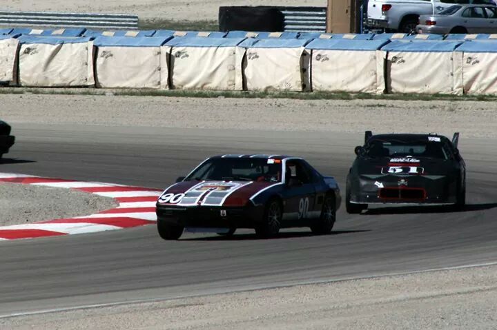
Correct me if I'm wrong, but this is your car now correct? (The second #51 car. The #90 car is mine).
|
|
|
|
DonP
|
OCT 16, 11:11 AM
|
|
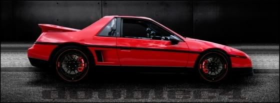
That's the car as it looks today. With an area 51 theme. I'm trying to recall where I saw some stuff on your build. Here on the forum?
We've already signed up for the next Miller Motorsport Park LeMons race, October 3-4, 2015.
Don[This message has been edited by DonP (edited 10-16-2014).]
|
|
|
|
DonP
|
OCT 16, 11:22 AM
|
|
Rich just corrected me about the lower control arms. We used 5/8", not 1/2" bolts to the frame. So I made that edit. Just keeping it straight.
Don
|
|
|
|
Canyonflyer
|
OCT 16, 03:38 PM
|
|
| quote | Originally posted by DonP:
That's the car as it looks today. With an area 51 theme. I'm trying to recall where I saw some stuff on your build. Here on the forum?
We've already signed up for the next Miller Motorsport Park LeMons race, October 3-4, 2015.
Don
|
|
Yeah... I posted a short build write up after the Miller race. Will do another after the car is running again.
I spoke to one of your guys several times during the Miller weekend. He came over asking if we had any spare lug nuts on one occasion. I just wish we could have finished the race. Should have the 2.8 liter in the car next week. It's been slow going since Im the sole person working on it.
I've got my car signed up for Miller next year as well. Same number. Im also mulling over obtaining another car for that race as well. Either way, Look forward to racing with you all again.
|
|
|
|
DonP
|
OCT 17, 01:32 AM
|
|
The final component that we needed to fabricate prior to actually assembling the front cradle was the shock package. I say package because, like the rear DIY coilovers, we elected to build a DIY coilover-like affair. The rules pretty much made it a non-starter to buy an off the shelf coilover set up. Trust me, that would have been far easier and the direction we would have gone had we been allowed to. So we had to design something that would meet our goals of having an adjustable ride height as well as accommodate a larger selection of springs. As opposed to a real coil-over where the shock body incorporates an actual spring perch, what we did was have a stock shock mounted inside the spring perches.
Fortunately, when Rich had purchased the box full of parts that had supplied our rear coilover components, he had also got enough other parts in the lot to make our front setup. The only thing we still had to purchase was one nut/spring thingy. The gold part in the photos below. We got enough of the threaded tubes.


If you recall, Rich had a chance to go to a racers swap meet, where folks sell their used or surplus stuff to buy other folks used or surplus stuff. Nobody ever seems to be able to clean out their garage, but just swap the contents. Or at least that's how it usually works with us. Anyway, Rich hit on of the sellers with ten minutes left in the swap meet. The seller didn't want to take it home, so he got a box full of coilover related stuff for next to nothing.
Because we couldn't use actual coilover shocks, we used the KYB shocks for an '88 Fiero. These are stock replacements.
Rich made two plates that would act as the spring perch. One for the top of the shock package, the other for the bottom.


The bottom perch would actually have the threaded tube resting on it, with the shock passing through. So the bottom perch for the threaded tube received a second concentric hole for the shock body to pass through.


Obviously there would need to be a mechanism to hold the threaded sleeve centered on the lower perch. Just sitting on the perch like this wouldn't do it. In the background you can see the top shock/spring mount plates. The stud on top of the shocks pass through tis plate as well as those rubber grommet/washers that come with the shock.


So Rich cut a piece of exhaust tube that would fit inside the threaded tube but fit outside of the shock body.


We had to smooth out a seam inside of the threaded tube for the locating pipe to slide freely.

The top shock mount also had a piece of exhaust pipe welded on to center the spring. This pipe did not pass through the plate because the top shock mount stud needed an attachment point.


Rich made a couple tabs that would accent a pass through bolt to mount the top plate to our yet to be built chassis pick-up points.


On the bottom perch, Rich made similar mounts, but a bit wider to accommodate the lower shock mount. This would allow the whole assemble to move with the suspension.


Once we got this far, we could start to see how everything would come together.


NOW we were ready to try assembling it.
|
|
|
|
Francis T
|
OCT 17, 01:33 AM
|
|
Checkout the link below and the plywood front air damn, rear wing, and other mods, like the pushed-out front fenders to lower wheel well pressure. It's kind of like the lyrics from that old song:
She ent pretty, but she sure can cook
In this case she ent pretty, but she sure is fast
Add a front air damn and rear wing and with your other mods, you should do good.
BTW to keep cost down and thus penalty laps, the rear wing is also wood, built up with ribs, spars, and covered etc etc.
He now races in chump only, the competition is better. Good luck
facebook.com/pages/MR2-Biohazard/205651116117996
|
|
|
|
DonP
|
OCT 18, 11:06 PM
|
|
Looking back at the last couple pictures I posted, one problem jumps out. The shock package is very unlikely to be able to pass through the stock spring pocket of the front cradle. I'll go a step further and say, there was no way it would work.
As you might suspect by now, we aren't too shy about making modifications as needed. Or as we want to. The obvious solution was to remove a portion of the cradle that included a portion of the spring bucket. And so we removed the shock tower/support as well.


So, having made that decision and modification, we started to build the front cradle. Knowing that it's important to have a proper, precision surface table to do this type of work, we of course headed to Lowes. We carefully selected their finest 3/4" plywood and wrapped it with butcher paper for proper marking. We set up and leveled Rich's jig on some adjustable saw horses. On top of this we placed a frame to support the plywood and presto! we had a surface table. This was the same frame he used on building his IMCA Modified car.


We knew the ride height that we wanted the front cradle to sit at. So we were able to put together a couple metal pieces to support the frame the desired height off the surface. Obviously we took as much care to keep everything square and level as possible.

Rich had some very specific goals for the reworked front end;
> 3 ½ degrees negative static camber
> Under ¾ degree of loss in camber in 10 degrees of chassis roll in cornering. Most front
suspensions create negative camber when you jack up the lower A frame. But when you
add body roll it creates a loss of camber and that is one of the reason static camber is
added in race cars.
> No change in caster as the suspension goes through bump and rebound
> 6 degrees of caster
> 4” roll center
> 10 percent anti dive
> Less than .030 bumpsteer
> Expanded selection of spring rates
My eyes kind of glazed over, and I went back to sweeping the floors.
The process went something like this. We set the cradle at the desired ride height. we then attached the lower control arms with the proper spacer to locate the arms front to rear.


Having the lower arms attached, we could determine a reference line between the two lower ball joint centers. This line gave us something to measure all other pick up points fore and aft.
We also located the centerline of the cradle. This center line, drawn on the surface table/plywood gave us ability to locate any other point left and right.

The fact that we now had some reference lines, meant that we could start to lay out the suspension. Rich and I had purchased a suspension design program from William C. Mitchell software ( http://www.mitchellsoftware.com/prod01.htm )several years ago. So the plan was to mock up the suspension with the parts we had decided to use, measure everything, input into the program and see what the results were. From there we could move points in space and see what the resulting changes were. And presto, we would have a new suspension with better geometry.
Yeah, right. Like it would be that easy.
Anyway, the next step was to add the front spindle upright to the mix.

With the upright attached, it becomes possible to determine the height of the lower ball joint. Simply put, if you know the diameter of your wheel/tire combination, you can determine how high off the ground plane the center of the spindle (in this case hub) will be. If you raise the hub until it's at the ride height, the lower ball joint and control arm can be determined. They are all bolted together. One moves they all do. We actually took measurements on another Fiero to try to determine how much the tire would be compressed when on the car. So we added in a fudge factor to the center of the hub to allow for that distortion of the tire.
Once the height of the lower ball joint has been determined, we used a small screw jack to position the arm on the Z axis, how high the arm is off the floor plane.

You may notice at the very bottom of the picture, just in front of the support under the screw jack, we have that reference line that was drawn from ball joint to ball joint.
With the ball joint positioned on all three axis, Rich could start to position the other components. At this time we tried to fine tune the actual ride height of the cradle. Because the data was already published on locating the center pivot point on those fancy MOOG ball joints, we could easily find the height of the actual pivot point.


Hopefully, the pivot point on the inner heims would be very close to the same height, meaning that the lower control arm was level. That was the ideal.


These are somewhat out of sequence, but we took a look at how the spindles would look at the static camber we were after. Ignore the readings, this was staged for photos.

Once the hub is located, with the static camber desired, we could start to look at other components such as the upper control arm.

Now it started to get even more complicated. We needed to fix what we could in place while allowing the freedom to manipulate components that could not yet be nailed down. Try telling an assistant to "hold this upright right here, without moving at all while I swing these other components around to see what happens. And don't move for three hours." Not likely. It actually took some time to figure out how to make this all work. We knew where the inner pivot points on the lower control arm HAD to be. They were fixed. We knew where the lower ball joints HAD to be. That was fixed. So the lower control arm was fixed and essentially immobile. We knew the amount of camber we wanted on the control arm. So that determined where, left to right or in and out the upper ball joint would be. So now, if we could position the spindle to the desired camber and slope backward which gives us the caster we could know exactly where the upper ball joint resided.

The solution came by welding small braces between the fixed lower control arms and the nut at the bottom of the upper ball joint while the caster and camber were where we wanted them.


Now we were getting somewhere. The inner pivots of the upper control arms were still floating and had to be locked down. But all the other points were fixed on all three axis. I wish I could say that having everything else fixed made the mounting of the inner upper control arms obvious. It did not.
We had some work ahead of us.
|
|
|
|
DonP
|
OCT 24, 11:23 PM
|
|
It was pretty obvious that we would not be mounting the upper control arms in the stock manner. After all, we had eliminated the control arm shaft as well as replaced the bushings with heim joints. And we had actually removed the stock mounting pad from the cradle. Locating the upper arm to cradle pick up points was our biggest challenge. the location of these points would affect every one of our target alignment goals.
I personally think that I had a reasonable understanding of how all this stuff was interrelated. I understood why unequal length control arms are used - to allow for camber gain or at least minimize any loss. But how do you determine or design in how much down angle is needed from the upper ball joint to the inner pivots of the upper control arm. 'Cause the angle of the control arm(s) also affect the location of the roll center.

If you lower the roll center by changing the angles on the arms, you can change the distance (mostly we are talking vertically) between the roll center and center of gravity. If the distance increases, you increase body roll. So what are the desired results we want? Rich set the goal of a roll center 4" off the ground.
Okay, but what if you want to have the 10% Anti-Dive that Rich was shooting for? (anti-Dive? see http://performancetrends.co...itions/Anti-Dive.htm http://en.wikipedia.org/wik...ension_%28vehicle%29 ) On our double A-arm type suspension, anti-dive characteristics are often accomplished by tilting the upper control arm.

But wait a minute, doesn't tilting the control arm front to back change the plane or line in the upper image that helps define the roll center? Yup. And it gets more complicated from there.
I'm not going to even try to define any of the steering/suspension geometry stuff beyond what I just wrote. First of all, I'm not an expert and will just open the door for a discussion I'm ill equipped to participate in. There are guys here on the forum that seem to eat and breath this stuff. Heck, I never even heard of Pro Dive outside this forum!
So back to the stuff I can talk about.
Realizing that there was no way to just hold the upper control arm in place Rich built a simple angle iron mounting plate that we could secure where we wished with clamps or weld tacks.


To the best of my knowledge, Elves came in during the middle of the night and tacked the upper control arm brackets at what would approximate the stock mounting positions. We now had the task to measure, as exactly as we could, all the suspension pick up points and pivots in 3d space. Let's see if I remember everything we needed to measure.
Each Lower control arm pick-up on the x, y and z axis.
Lower ball joint center/pivot point on all three axis.
Spindle center at ride height.
Upper ball joint center/pivot on all three axis.
Inner tie-rod pivot point , all three axis.
Outer tie-rod pivot point on all three axis.
Ever try to determine the center point of a ball joint or tie-rod joint? Luckily, there is published data available on-line to determine the center points of those high end ball joints used in NASCAR. For everything else, we had to resort to more primitive measures.


Given the X and Y axis that we had created on our surface plate, we could easily determine items located on those axis.

Here Rich is measuring the outer tie-rod pivot point. First he measured to the ball on the front or leading edge. Next he measured to the back or trailing edge. And averaged the two points. Next he did the same on the left and right sides. He then cross checked with a little math utilizing the measured radius of the pivot ball. Keep in mind that in order to get reasonably accurate results, it's necessary to do an actual alignment on the table to set Caster, Camber and Toe. Or we would have had to do it all had we not welded everything such that the camber and caster were fixed. Toe was the only variable to be set.

Back when Rich was building his last IMCA Modified car, http://www.fiero.nl/forum/F...ML/090867-3.html#p83 he invested in a height gauge. This cool little tool was very handy during this construction project.

We used this tool to take all of the Z axis or height measurements of all the components.

From this point, Rich input all of the measured values into the William C. Mitchell suspension analyzer program to see where we were. Ignore the figures, there just whatever came up for the pictures.


Wouldn't you know it, we hit all of our design parameters on the first try!
.
.
.
Maybe not.
I didn't record the number of changes we made with the corresponding re-measuring and inputting. But the time involve rolled into many days. Eventually we did arrive at a position for the upper control arm that should give us a setup reasonably close to our design goals. From this point we could fabricate the actual, final upper control arm pick-ups.


If you look closer, you can see that we boxed in the underside of the mount to strengthen the entire mount.


It now became necessary to consider the steering tie-rods and how to make them fit the package.


And we could finally cut our locating braces.

Now we had to duplicate all of our measurements on the other side of the cradle.
|
|
|
|
kennn
|
OCT 25, 01:27 PM
|
|
I'm curious what problem you are resolving with the reconstruction of the front suspension or what your design intent is.
Ken------------------
'88 Formula V6
'88 GT TPI V8
|
|
|
|
doublec4
|
OCT 25, 06:55 PM
|
|
|
|
|