I have seen quite a few new Fiero owners here over the years who have needed help with doing some basic trouble shooting and repairs on the Fiero electrical system, which as we all know can be troublesome at times.
What I offer here is a basic description of the types of tools available, how to use them and some wiring repair.
I welcome any other advice to help clarify things for the Fiero owners who are learning to repair their cars themselves or if you have any tips.
I plan to start this with what I think are the basics.
In my opinion a basic set of electrical tools need not be expensive and are fairly easy to aquire whether you go to Radio Shack a home improvement center or an auto parts store.
Lets start with the tools.
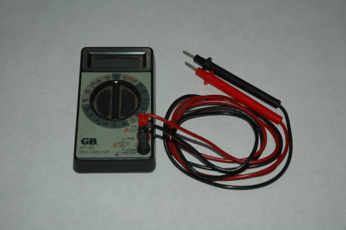
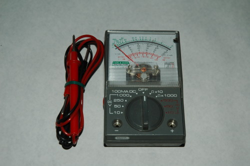
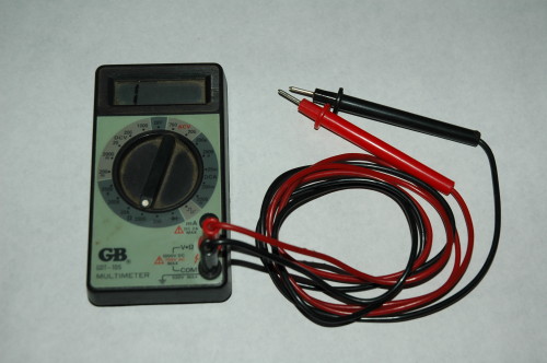
A Multi Meter, either digital or analog.
They come with two test leads, a red and a black and they usually run on a regular household battery.
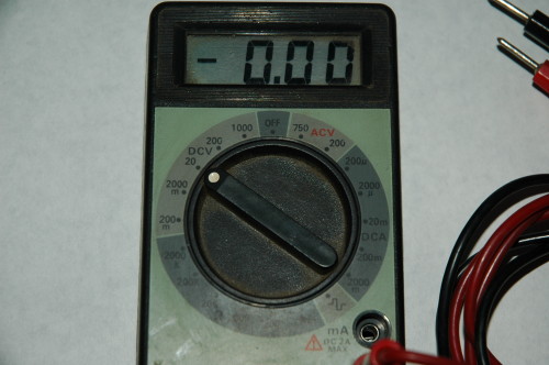
This is a digital Multi Meter, I recommend this type.
This is an analog Multi Meter, it does the same thing but the needle can bounce around if bumped.
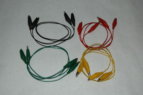
A small set of test leads.
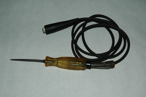
A 12 volt test light.
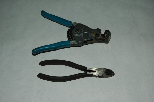
A wire cutter and a wire stripper, more on the wire strippers later.
Another type of wire stripper also used with crimp connectors, more on those later.
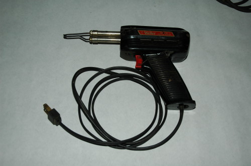
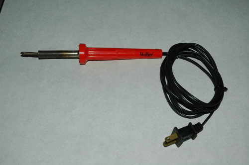
Soldering irons.
A Weller brand "gun" type which I prefer as it heats when you pull the trigger and cools off fairly quickly when you release the trigger, it even has a small light that shines on the work when the trigger is pulled.
A Weller brand "pencil" type, this you plug in, it heats up and is always hot, works ok and burns you even better if you're not careful.
------------------ Where will the road take you today?
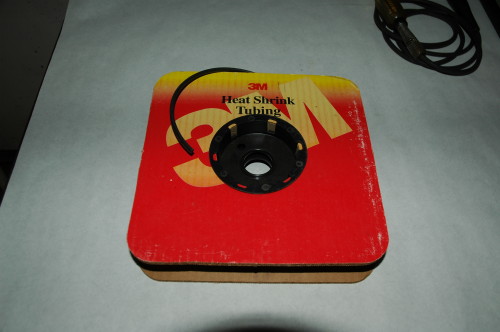
Heat shrink tubing and a lighter or matches. I have a spool of the tubing, (shown here), that I bought at an electronics store, it's the right size for most Fiero wires. You can get small variety packs at Radio Shack and most hardware stores, they have several small pieces for different sizes of wires, more on it later.
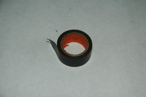
Electrical tape.
[This message has been edited by fierohoho (edited 03-17-2007).]
On your Multi Meter plug your red test lead in to the volt/ohm spot and the black test lead into the ground spot.
If you set the Multi Meter to the 20 VDC position...
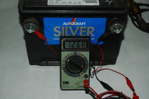
...you can use it for testing for power. Here I have attached test leads to the leads of the Multi Meter and then attached them to a battery, as you can see the reading shows the battery is at 12.68 volts.
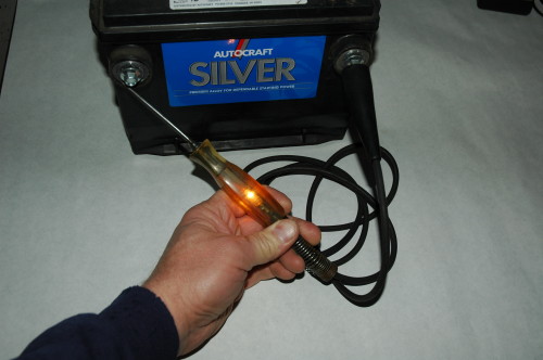
You can also test for power using the 12 volt test light. Attach the clip end to a good ground or the negative side of the battery as show and the other side has a point to probe for power, the point can even be used to pierce a wire to test it for power. When the light goes on you know you have power at that point. This is a good tool to use at the fuse block, if you look at the top of each fuse you can see it has exposed contacts on either side of the amp numbers and if you ground the clip on the test light and find power at one side of the fuse and not the other with the probe tip it's likely the fuse is bad.
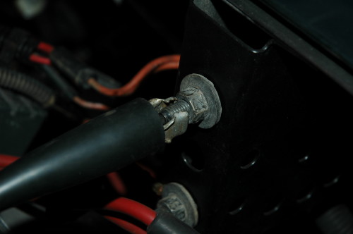
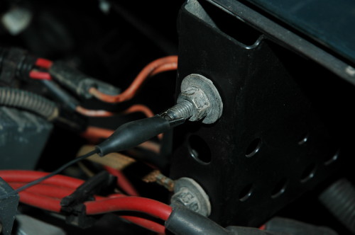
A couple pics of the test light and a test lead grounded to the rear deck lid hinge bolt.
[This message has been edited by fierohoho (edited 03-17-2007).]
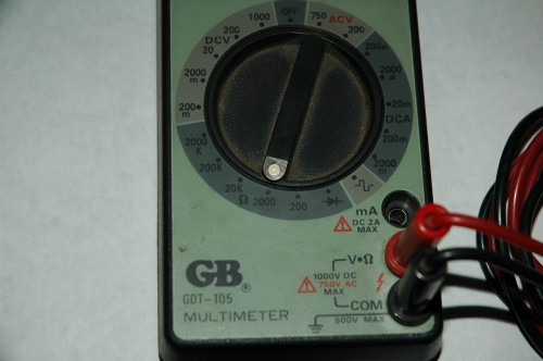
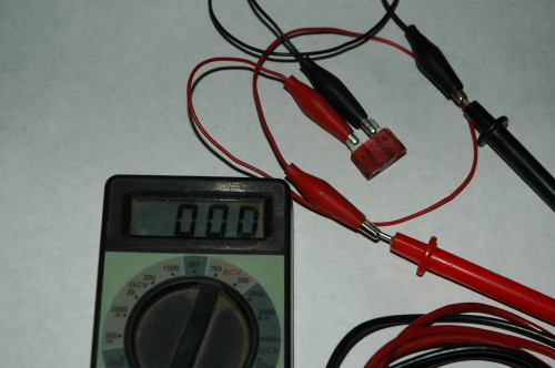
You can use the Multi Meter to check fuses by setting the meter to 2000 OHMs as seen here.
Your readout should be showing a 1 which indicates no resistance as seen here.
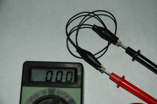
If you attach test leads together again as shown her and then attach them to the fuse, (yes you can just touch the leads to the fuse but you try doing that and taking pictures), you will see the fuse is good when the readout goes to 000. This is also a good way to check light bulbs.
The same thing happens if you put a test lead across the leads.
This is a good tool I've used during my 3800 engine swap. I will attach one lead to a wire at the engine and then probe the harness end to determine which is the same wire, when the reading goes to 000 I know I have it.
There are numerous way to use the Multi Meter and I'm betting other will post their ideas here.
[This message has been edited by fierohoho (edited 03-18-2007).]
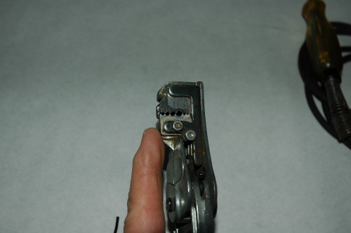
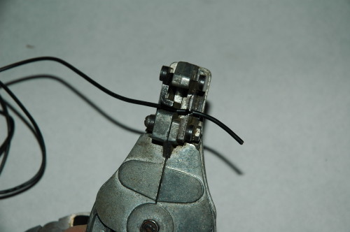
This is my favorite type of wire stripper, it has small holes for different gauges of wire.
The wire is placed in the jaws with the end to be stripped poking out the side with the different size holes. Have it set in the hole that is about the same diameter as the wire and not the insulation, extend it out as far as you want it stripped like this...
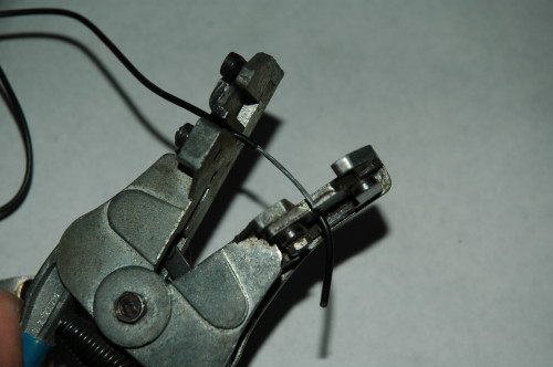
...then squeeze the handles together, the wire is held on the left by the jaws and the insulation is cut and pulled off with the right side. No more cut fingers from a sharp blade trying to strip by hand.
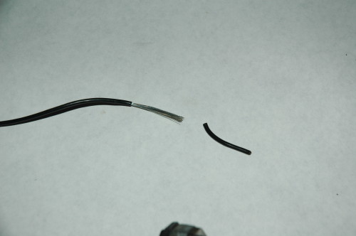
It leaves you with this.
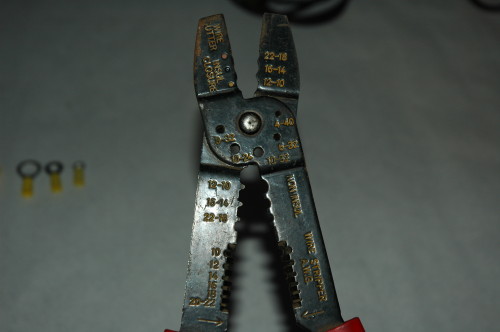
You can also use this type of stripper that works the same but you pull the wire against the tool as you squeeze the wire in the cutter hole. The cutter holes are the ones at the bottom of the pic on the inside of the tool and are various sizes also for different size wires.
[This message has been edited by fierohoho (edited 12-01-2008).]
Now a little on heat shrink tubing. I use it exclusively when I splice a wire as it seals the wire much better against the elements than a crimp connector and electrical tape.
The biggest thing to remember is to put it over the wire "BEFORE" you solder the splice. You have no idea how many times I've had to cut a splice apart just to add the heat shrink tubing because I forgot. It's also important to size the heat shrink tubing to the wire you're working on, too big and a poor seal, too small and it may not fit over the splice.
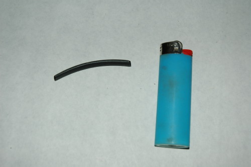
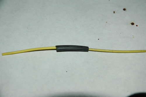
Here's a small piece of tubing before it was heated.
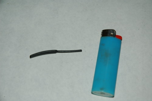
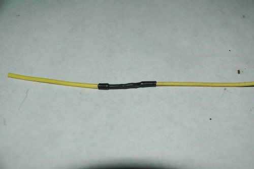
Here's the same piece after I heated one end of it. You can see how much it shrinks down and that is what keeps the splice clean and dry.
[This message has been edited by fierohoho (edited 12-01-2008).]
Now lets talk about connecting together two wires.
First lets look at crimp connectors. I think they are fine if you use them in the passenger compartment of the vehicle as they won't get wet, corrode and fail.
I do not recommend them for exterior applications where they can get wet as they will eventually fail unless they are sealed up somehow.
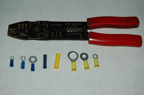
Here are a few of the many types of crimp connectors and a crimping tool.
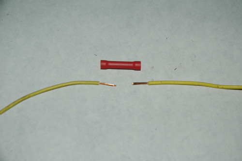
To join two wires using the crimp method you start by stripping off a small section of insulation from the ends of each wire.
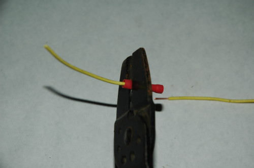
The wires are pushed into the end of the connector and squeezed with the crimping tool. The connector is usually blue, red or yellow depending on the size needed for the gauge of wire. The crimp tool had three colored dots where the connector is crimped to match the color of the connector, match the colors and squeeze the connector just next to the flared end, doing it this way and you generally can't over squeeze it. Insert the other wire in the other end and repeat.
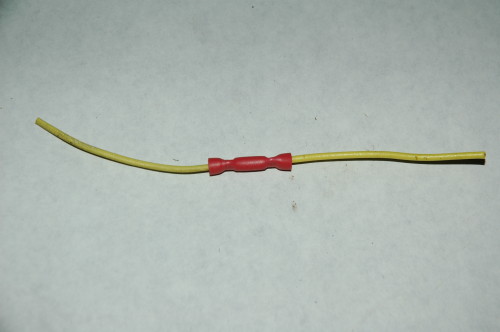
This is what the crimped connection looks like when done.
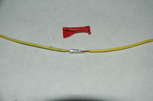
Here I have removed the connectors insulation so you can see what happened. You can also see how poorly this type of connection protects the wire from the elements.
[This message has been edited by fierohoho (edited 03-17-2007).]
One tip I have is that when you solder wires you will almost always have a few drops of molten solder fall from the wire, place an old mat or a piece of cardboard under the work to protect whatever is underneath.
Start by stripping the ends of the two wires about 3/8" to 1/2", if you're going to seal the connection with heat shrink tubing slide it over one of the wires now.
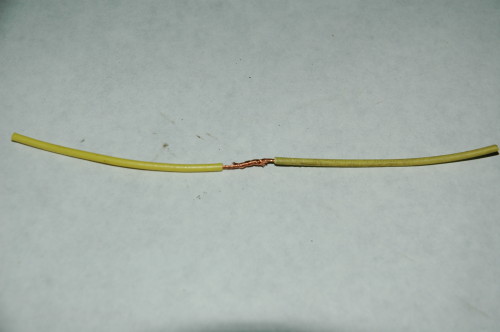
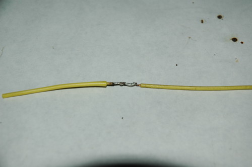
I then twist them together parallel. Make sure the ends lay flat against the wire so nothing can poke through whatever you cover the joint with and cause a shorting condition.
The key to a good solder joint is in the wire being clean and shiney, if you have a wire that is a little tarnished you can clean it up using a piece of sand paper, steel wool, a scotch brite pad, anything to make the wire shiney.
Once the wires are clean and twisted together it's time to heat them with the soldering tip. Place the hot tip on the wires and let it heat them a few seconds, then touch the end of the solder to the wire and tip, when it starts to melt the solder, lightly move the tip across the wire joint to help spread the solder along the joint, the solder will "flow" onto the wire when hot enough.
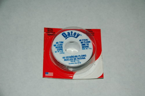
When it looks like the joint is covered it will be silver in color, you can stop and let it cool. There will be a little smoke when you do this, that's from the rosin core in the solder, this rosin core helps clean the wire a little more and it helps the solder to flow onto the wire.
When the connection has cooled so you can touch it with your fingers and not get burned slide the heat shrink tubing over the splice.
Now heat it with a match or lighter and shrink it down, as you heat it move the flame back and forth along the tubing, it will shrink one side more than the other so also rotate the wire as you do this. That's it, you're done.
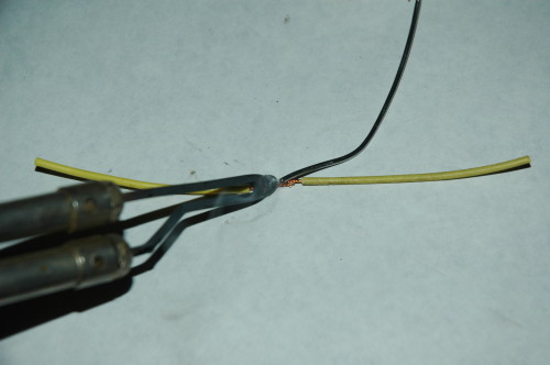
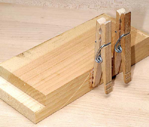
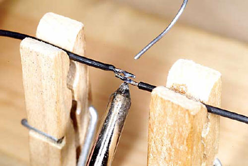
Here are two pics I found on the web of a neat and easy to build extra pair of hands for holding two wires you're going to solder.
There you are folks, the basics, fierohoho style.
Please feel free to add to this to help those that need it.
Steve
[This message has been edited by fierohoho (edited 03-17-2007).]
What a great how-to. It is nice that you take the time to share your knowledge, to many times the basic fundamentals are over looked and taken for granted. Great Job.
I might suggest a butane powered soldering pencil, no cord to lug around if you need to solder 'on the car' instead of your bench.
I also prefer autoranging DVM's myself, but i dont carry my good fluke on the road with me, but instead a cheapy 3.00 harbor fright special ( with lighted background.. for those times you get stuck at night )
Flashlights and mirrors are good too, so you can see where that stupid wire is going when you cant get daylight down in to see it.
I might suggest a butane powered soldering pencil, no cord to lug around if you need to solder 'on the car' instead of your bench.
That's a good idea.
Also with the small soldering guns and irons the usually don't have a very big draw.
My Weller gun has a dual heat of 100 and 140 watts controled by the trigger pull, pull the trigger half way and it's the 100 watt, all the way is the 140 watt.
This gun is small enough so if you have a 300 watt power inverter you can run the gun on your car battery if an electrical outlet isn't handy.
nice write up .....just as a suggestion ....maybe you might like to add " how to test sensors" if its possible without requiring another car to swap out onto as a test . i know it would be valuable info to me
------------------ It isnt re-creation....its recreation!!!!
Excellent write up ... + for you. One tip I would recommend, instead of using a lighter or matches for heat shrink, just use your pencil type soldering iron. run the side of the tip back and forth along the heat shrink, works like a charm ... and no open flame required. If you have a heat gun (kinda like a blow drier on steroids, but not everyone has one) they work great too.
Excellent write up. I have a few ideas to add from my own experience.
1) I prefer to use clear heat shrink tubing for most jobs. It's not as widely available as common black tubing, but you can usually find it on-line or at a wholesale electronic supplier for about the same price as black. Clear tubing allows you to inspect the connection at any time, and you can also place wire labels under it.
2) Even though insulated crimp terminals are handy, I prefer to use uninsulated terminals and then cover the crimp barrel with clear heat shrink tubing after crimping. Uninsulated terminals require a different crimping tool, but the final crimp is much more secure ... and you can visually inspect it. The heat shrink tubing also provides some measure of wire strain relief at the terminal.
3) Whatever kind of terminals you use, I highly recommend buying a ratcheting crimp tool designed for those specific terminals. A ratcheting crimp tool is much more likely to produce a good crimp, and thus a good connection, and the results will be much more consistent from one crimp to the next than with a cheap tool.
4) It is very important that whatever wire stripper you use (like the very good design fierohoho shows) cleanly strips the insulation from the wire without nicking the wire itself. A nicked wire, or even a single nicked strand in the case of stranded wire, is a point of future failure in a high-vibration environment like an automobile and is cause for rejection. Many wiring intermittents can be traced back to a nicked wire, often from a poor repair made many years earlier.
5) Finally, I would highly recommend an inexpensive heat gun for use with shrink tubing. It produces more consistent results and makes the job much easier, with less danger of damage to the shrink tubing or the wire insulation.
Decent quality tools usually cost a little more (sometimes a lot more) than cheap tools, but they almost always do a much better job and are an investment that will last a lifetime.
[This message has been edited by Marvin McInnis (edited 03-19-2007).]
Great thread!!! Props.. I was looking for one like that.
Quick thing I would like to ask/add? How do you test if all the idiot lights are working, other than taking the dash apart and looking at the bulbs?
-M
As I recall when you turn the key to on but not all the way to start they should light up as a test, if not you have to pull the back cover to the dash pod and check the bulbs one at a time.
To pull the top rear cover it's only three screws on top, T-15 torx bit as I recall, and two T-15 screws at the bottom.
All screws can easily be seen through the windshield if you're not sure where they are.
The bulbs can be checked using the same method I showed to check the fuse.
Originally posted by fierohoho: As I recall when you turn the key to on but not all the way to start they should light up as a test, if not you have to pull the back cover to the dash pod and check the bulbs one at a time.
To pull the top rear cover it's only three screws on top, T-15 torx bit as I recall, and two T-15 screws at the bottom.
All screws can easily be seen through the windshield if you're not sure where they are.
The bulbs can be checked using the same method I showed to check the fuse.
Well turning the key doesn't light all of them up. (that's what usually worked on other cars,so I tried that first) Leads me to believe that some of the lights are burned out. I'll follow your advice and do step 2 (removing the cover) next and test all the bulbs.
Some who buy multi meters (VOMs) may benefit from a feature not discussed (I think). That is current measurement . Look again at the sockets shown on the VOM in the picture. There is a socket at the top labelled mA (milliamp). The owners manual will explain how to use this. Such a measurement can be taken if a gremlin is running your battery down (parasitic drain). With all switched consumers off, including the ignition key out, very little current should flow from your battery (thousandths of an amp = one milliamp). For example the latest new cars loaded with computer gadgets might draw 60 milliamps. The Fiero much less if any. So If you have a problem a proper hookup of the VOM in milliamp mode can help detect a problem which could drain your battery , such as a stuck-on switch or small lamp.
If you have used your VOM in voltage and continuity (beep) you are used to measuring ACCROSS points,but current is DIFFERENT. You measure BETWEEN by inserting the VOM between the points. In the case of checking parasitic drain first the VOM is carefully set up with the mA socket position. The ground cable is loosened from the BAT. One VOM lead is placed on the BAT ground lead terminal, the other to the removed BAT cable connector. Current flow is indicated on the VOM in mA (milliamps). Note if your VOM only has mA capability (as opposed to A capability-full amp, not fractional) and you have a lamp drawing in excess of the mA the VOM fuse may blow (replace it). Many VOMs have 10 amp capacity. Read the owners manual. If there is excessive current indicated start looking for lights left on or other "normally off" consumers of current (an art in itself).
Edit: I just noticed in the VOM pic that the socket says "2 amperes max." This is good because it will probably allow detection of a "gremlin" small light without blowing the contained VOM fuse.
Edit 10-1-14. I have just read thread "Parasitic battery drain-what am I missing?" It is an excellent hands- on and "prompted" trouble shoot by knowledgeable people to find a real current drain. It seems a good supplement to this thread.
[This message has been edited by hobbywrench (edited 10-01-2014).]
This is a fantastic How-to. I appreciate the extra details you added, and all the pictures. It eliminates those odd blank spaces when something seems simple but isn't.
I just bought a '86 Fiero 4 Cyl. 2.5 L. 5 speed manual, which once had A/C. There has been a switch installed on the dash to turn the radiator fan on/off. No A/C now. Since I overheated the car once by leaving it run at idle while parked and forgetting to turn the fan on manually, I wish to return the radiator fan to automatic. . . . I own a rectangular (Four Seasons 35906) radiator ran relay (4 wires, #12 red, #12 blk/red stripe, #16 black/white stripe, and #16 green/white stripe) and wish to get the vehicle back to automatic radiator fan. . . .I cannot locate this type relay in either of my vehicles compartments. It is supposed to be on the drivers drivers side, front compartment. At that location is a 'square type 'Santech Ind. MTO636' which I believe was used to switch the radiator fan in cars with A/C. .I have located the coolant temp sensor and it must be hooked up correctly to the dash temp gauge as that gauge works fine. I have no idea of what sensor controls the radiator fan relay (same one????). Hoping someone knows what sensor is used and where it is located. . .. I checked the 'Four Seasons 35906 radiator fan relay' (rectangular) I own and the two #12's are switched by voltage accross the two #16's. . . .My car had A/C at one time so the fan relays in the front compartment are square shaped 'Santech Ind MTO636' type. I am at a loss as to what type of sensor is called upon to feed voltage to the #16 control wires onto either of my radiator fan relays. . . .As one can tell, I am in need of enlightenment as none of my books even mention this fan relay. . . . . . . in advance, thank to 1 & all. . .chas.
Chas, Do you have a factory workshop manual? I have not looked in mine for your problem, but recall the charts are pretty helpful. They typically have a logic tree with references to actual pictures of the relevant sensors and wiring. I think my manual is 85 GT specific , but if you want I will look at the fan charts for you. Don't think there are pn's, but the manual is perhaps an aid in understanding if extensive mods have been made to your car. I think your thread would get better response in the "technical" section.
This is a cut and paste from a post Bloozberry commented in about how to tell what gauge of wire is in the Fiero using the wiring diagrams in the Haynes or factory service manuals.
If you're building your own harness, then you really should get a manual which shows you the size of the wires used in the stock configuration. While some people use just any old wire they can come across, the gauge of the wire is chosen to support the amount of electrical current (amperage) of the total current draw on any given branch of a circuit. If you over-size the wire, there aren't any problems except that it's harder to work with and can add more than a few pounds to your car. If you under-size the wire, you risk melting the insulation and having shorts and even fires.
Here's an example of a typical wire diagram: The number just before the color of the wire (for example "1 ORN" at the top) indicates the gauge of the wire that's used in metric. A 1.0 is equivalent to 16 AWG. All of the wire diagrams show several different wire gauges throughout. You can't always judge the gauge of the wire by looking at it's outside diameter since different insulation materials and thicknesses are often used. If it helps, here is a conversion chart from metric to AWG sizes: