Hi All. I'm investigating why my 88GT temp gauge slowly increases while the car warms up (few minutes) to where it is Pegged or flutters around nearly Pegged. Direct reading of the anti-freeze temperature with a thermometer in the thermostat neck shows engine temperature is normal. Also, the resistance of sensor plug pins A and B to ground was as expected for operating temp (data now lost.) Reading through the 'pegging' posts here on the Forum I think this is a different beast, and if memory serves, goes back to a few years ago when I melted some wires in a brief, direct short-to-positive of one of the green harness grounds at the starter solenoid. During that regrettable, exciting episode, I removed the harness and checked every wire, repairing those with sagging or melted insulation. To the best of my recollection the temperature gauge read normally before the short-to-positive debacle.
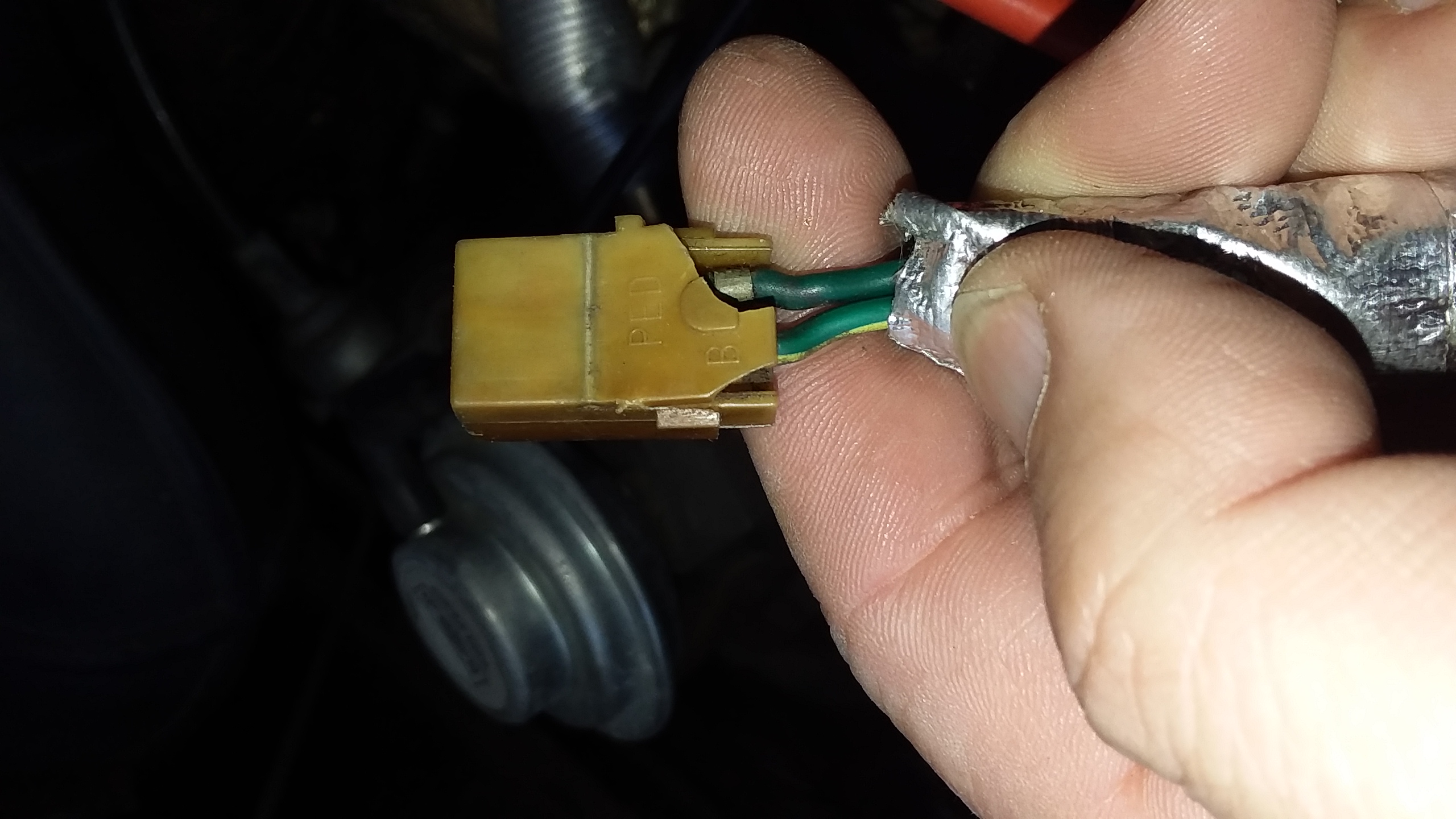
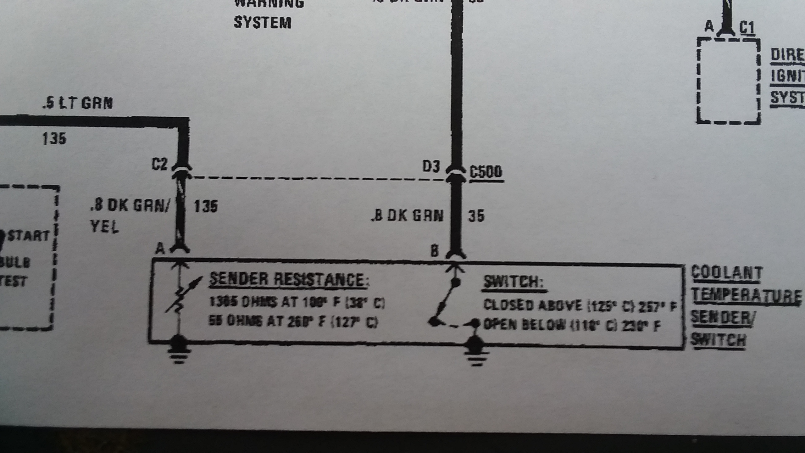
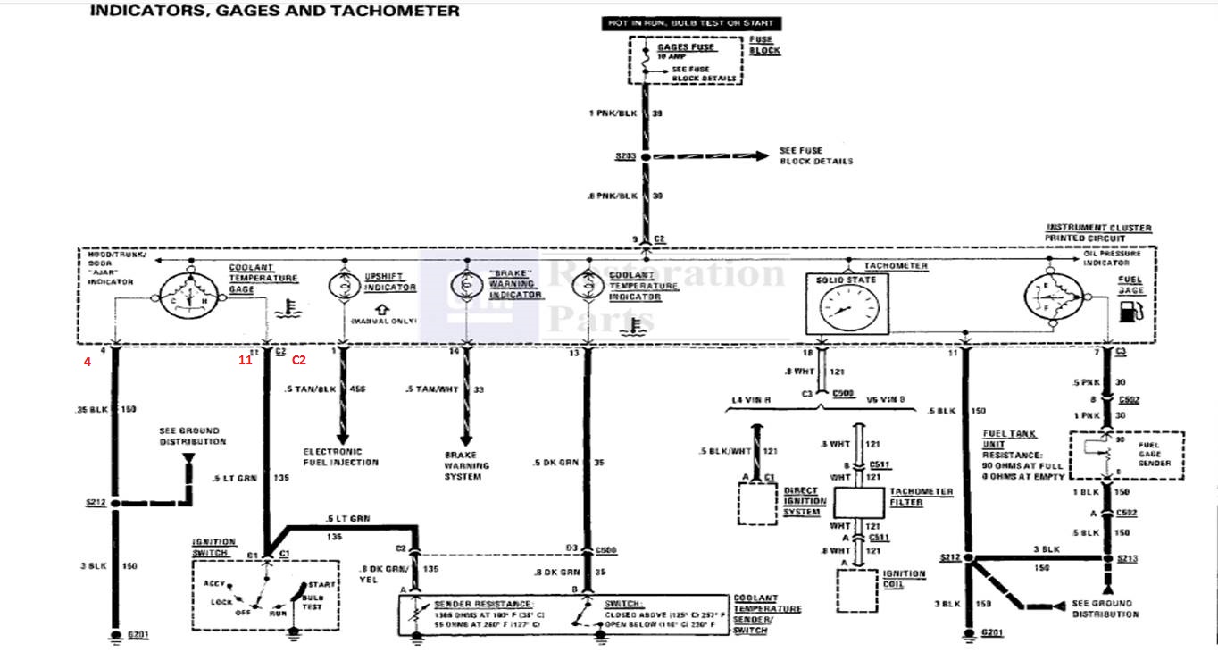
So, on to the present conundrum: I have now noticed that the plug A and B wire colors do not match the factory diagram. In my car the A pin connects to a Dark Green wire and the B pin connects to the Dark Green w/Yellow trace. This is the exact opposite of what I was expecting to see. I've got the dash taken apart so I can measure the wire resistance at plug C2-pin 11, to look for shorts, but the wire going into C2-pin 11 is Dark Green. The diagram shows the Dark Green w/Yellow trace wire switches color to Light Green at the fire wall so pin 11 should be Light Green, not Dark Green. So I've got the wrong color and the A/B pin wires swapped.
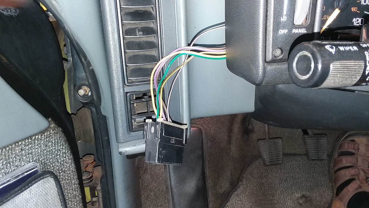
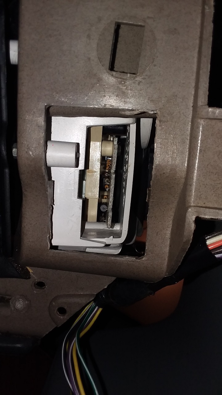
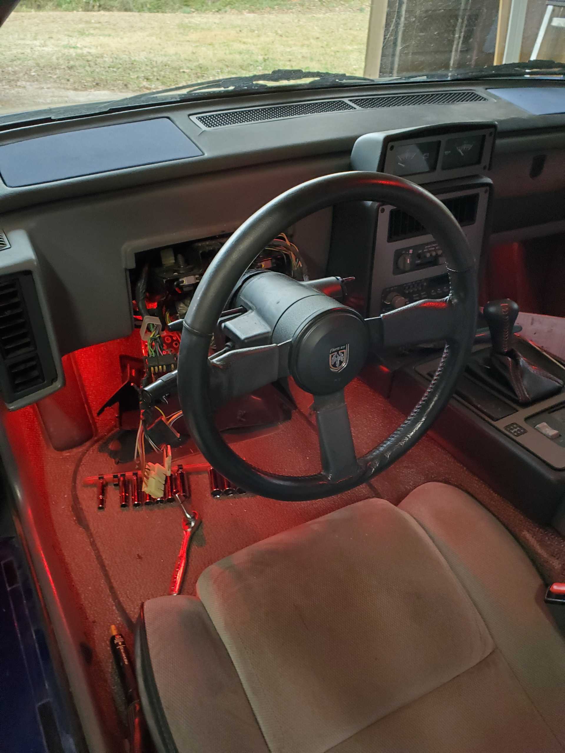
What follows are pictures of the Plug and Sensor, and excerpts from my PDF manual. This makes the diagrams, unfortunately, very hard to read. At this point my head is spinning so any thoughts will be appreciated.
Good Grief, so this IS the 'repair' that a PO has done to the car, swapping A/B and pins 11 (C2) and 13 (C3). I had never really paid attention to this and am surprised it fixes a GM screw up. Oh well.
Now for additional data, I just measured the resistance between plug pins A/B (infinity) and to ground (infinity) and from plug B pin to connector C3-pin 13 (0.1 ohm) and plug A pin to connector C2-pin 11 (0.1 ohm) which shows:
1) No short on the gauge wires to ground or each other (i.e. not victims of the old melt-down)
2) Good continuity on the wires to the gauge (not severed, etc.)
Since the sensor was measured in the past to read resistance at temperature, this would seem to suggest that the Temp Gauge was damaged in the short affair.
This just keeps getting better. I'm looking at the gauge now and found a PO had epoxied this wire lug in place. I can't imagine what this rig is supposed to be doing.
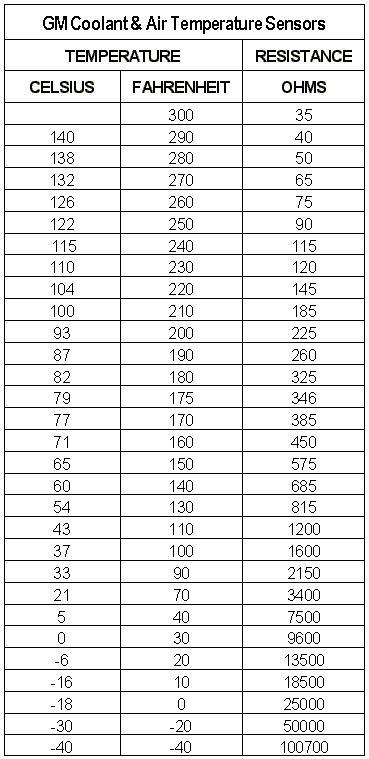
Another piece of data. Currently measuring the anti-freeze temp at 70 degrees and the sensor-to-ground resistance of 3700 ohms. This is 300 ohms higher than the table value of 3400 ohms (see below.) So, not off by much, but is that enough?
I guess you are going to tell me to test the gauge but I don't have any resistors. Looks like 1600 ohms (100 deg), 145 ohms (220 deg), and 75 ohms (260 deg) would conveniently read onto the major Tick Marks on the gauge.
Partial cut & paste from one of my previous posts might be helpful.... The coolant temperature sender for the dash gauge/light is located behind/below the ignition coil. Most older cars have a gauge or a light, but the Fiero has both, so the 2-pin connector is just that, one for the gauge and one for the light. The factory connector often degrades over time and you can buy a replacement connector, Delco #PT110
To check and see if everything is working correctly...
1. Check resistance on sender terminal opposite of the cutout/notch (for the gauge needle) it should measure around 3.5 to 4.5 ohms at 68 to 72 degrees F.
2. Then put a jumper wire from the green wire (for the red dash light) to engine ground with the ignition on and the red light should illuminate.
3. Now the other, put a jumper wire from the green/yellow wire (for the gauge needle) to engine ground to see if the needle pegs (if not the gauge is probably toast).
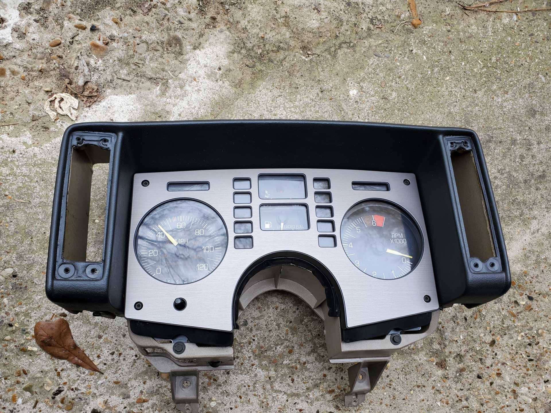
That's how everything should work. Also, the temp gauge is not linear and the 220 print is incorrect from the factory, if you count the lines/steps the 220 should say 180, mine runs 200 in that position. (I covered my 220 with black decal so it only has 100 on the far left and 260 on the far right, similar to E and F on the fuel gauge) Lastly, if you cannot calibrate the needle properly, a good estimate of where the needle goes on the bench is to point it at the bottom of thermometer (like yours is in the photo).
The factory routed wiring causing the gauge to peg is a separate issue. I'm not a fan of switching of wires behind the instrument cluster and sounds like the PO might have done it, that is a popular mod to correct a factory flaw in the original GM wiring engineering, voltage being routed incorrectly which causes the temp gauge to peg/slam every time you start the car and eventually it damages the gauge. You don't have to switch wires behind dash to correct this factory flaw and prevent gauge from pegging/slamming on startup. There is an easier and safer way, all you have to do is disconnect/remove the double light-green wire from the ignition switch located on top of steering column and tape up the end so it doesn't touch anything when left hanging under the steering column (I actually taped a note on mine so future owners who find it know why I did it). This bypasses the red temp light bulb test feature on startup and the gauge will no longer peg/slam on startup and the temp light will still work, it just won't light up anymore briefly when you start the car.
[This message has been edited by Skybax (edited 02-06-2022).]
I just fixed an issue similar to this about a week ago. My needle actually was off the gauge and lying in the display window. Ordered a new plug for the sensor, and sensor from the Fiero store,and a tested good gauge from someone here, used. Carefully pulled the cluster, replaced the gauge first,then reinstalled it. Not too bad a job,really. Then replaced the sender. I was unsure if polarity mattered. I had a 50-50 chance. So, I started the car and let it warm enough to show something. Nothing happened. So, I had a relaxing adult beverage and let the car get good and cold.Changed the two wires,and soldered the connections, then shrink wrapped it with a short piece of loom over it to look factory. Works perfect. The previous owner had used the cold start sensor by the coolant fan switch,put in an aftermarket sensor , and ran an elaborate path of wire to the top of the instrument cluster, and put in a cheap temp gauge. I have a 3.4 in mine. But externally looks like a 2.8. I am sure it is the same. And no, in 25 degree weather it kicks right off,so I don't need that cold start injector. If this cold would pass, I am about to pull the cluster again, and put the white gauge overlay in it. I also picked up some needle paint from the gauge guys for a couple of bucks. And lastly, putting red leds in the cluster to finish it out, Tach did not work either.Replaced the tach filter, and it works now too. Step back, don't overthink it.
I would do what I did to fix your problem. You Tube has videos for all that stuff, if you are unsure.
[This message has been edited by gatorfrey (edited 02-06-2022).]
My gauge was not working after the engine rebuild I did. The plastic outer shell had disintegrated due to heat. I wasn't worried, because I figured the same thing, that it was just a resistor with a value that changed with heat and there was no polarity involved. I replaced the old temp sensor with a new one. When I started the engine up, I was waiting for the temp gauge to start reading and it never did. So on a whim, I swapped the two wires. The gauge works fine now. I don't know how the circuitry is connected, but it requires that the wires be connected in a certain way. Just an FYI for everyone in here.
quote
Originally posted by PhatMax:
I could be wrong but since it’s really just a switch, not sure it matters which side the wires are on….no ?
[This message has been edited by eti engineer (edited 02-08-2022).]
I am not sure about your year / model FIERO, but on my 1988 the temp gauge would PEG to “HOT” on start up. The previous owner said to bang on the top of the dash board and the needle would fall back down. It took me five seconds to read on the forum about the incorrect way that Pontiac wired the meter. Have you searched on Google to see if anyone else has experienced the same issues?
This just keeps getting better. I'm looking at the gauge now and found a PO had epoxied this wire lug in place. I can't imagine what this rig is supposed to be doing.
With factory wiring, the hand will peg all the way to the top right at startup. The end of the hand will snag into the soft shield and hang at the top. Looks like they glued in the terminal as a bump stop to prevent it from hanging.
I could be wrong but since it’s really just a switch, not sure it matters which side the wires are on….no ?
It does make a difference which wire is plugged to which terminal on the sending unit. One terminal for the light is an ON/OFF contact. The other terminal for the gauge is a variable resistor. You can determine which wire is for what function by inserting a paper clip in the connector and grounding it to the engine.
Gauge sender uses different thermisistor and values won't match ECM charts. And Most Gauge Senders ground to the engine... Gauge coolant sender... 1365Ω at 100°F(38°C) 55Ω at 260°F(127°C) From any Fiero FSM
If you have Arduino kits, old dead things, etc, use the pots to dial in those exact value to test the gauge and wire to the sender. Or buy RD gauge testers.
If gauge reads wrong... Many things can make any dash gauge lie to not working. Even if gauge wiring is good, iffy grounds nearly anywhere in the car can still make problems.
Some Examples: Most Gauges have Resistors on back that's never covered in FSM Alldata and more. Careful removing/tighten the nuts holding them often cleans oxides etc and work better. Using Deoxit etc may help too. Dash back and SS clips often get crap connection over time too. removing/installing the Big plugs to the dash back, the board copper often have problems and can short out. Any crap ground in the engine bay or the cabin causes gauge errors.
Gauge may read 100% accurate but you compared to whatever just think is "Wrong." Even Sender/sensors near each other can read different temps because of coolant flow and exact design/manufacturing of each part. Plus Fiero temp Gauge and sender was never to be very accurate and why Most cars and truck have same setup but No Numbers on the gauge. Even Most new cars w/ dash gauges under ECM/BCM control don't numbers on temp gauge and even oil pressure gauge because idiots go into a panic easy and claim Warrant or worse for nothing wrong.
------------------ Dr. Ian Malcolm: Yeah, but your scientists were so preoccupied with whether or not they could, they didn't stop to think if they should. (Jurassic Park)
Dang, too bad I had already ordered $5 worth of resistors to check the calibration on the gauge.
Is it really correct that the temperature gauge was mislabeled by GM from 84-88 and they didn't fix that?? Well, I guess when you consider that the temp gauge & temp light wiring were reversed, and the service manual was wrong, for 84-88 without them fixing it, who knows what else was passed over?? Sheesh.
That should tells a lot in minutes even if need to remove the dash back plastic.
even if gauge is "accurate," senders can have 1% 5% or way more tolerance and gauge can read exact to x% higher or lower. And that's on top of location, coolant flow, and more. Dash gauges only are ballpark guides to being safe to having problems. You never trust them for real data because so many things make them lie.
Fuel and oil pressure often does same. even more because dealing w/ 0-90Ω in a lot of GM and other brands.
It does make a difference which wire is plugged to which terminal on the sending unit. One terminal for the light is an ON/OFF contact. The other terminal for the gauge is a variable resistor. You can determine which wire is for what function by inserting a paper clip in the connector and grounding it to the engine.
I performed the fix back during the Summer months.
Every time I start the car, I get a kick that it was wrong from the factory, and just...works...now.
Turn the key, temp light comes on, gauge does not peg.
it's the little things in life that are so satisfying.
So to wrap up things up, I tested the wiring (which was good) and the Temp Sensor and the Oil Pressure Sensor (which were bad, apparent victims of the 12v-to-gnd mishap.) Replacing them solved the two gauge problems. ...
But, in the process, now the Speedometer and Odometer don't work. I found some posts on how to check the VSS itself, but before I pull that out I'd like to know if this left-over 18-pin plug should be attached somewhere. I don't remember where that was when I took the lower dash apart to check the Temp and Oil Pressure wiring. I have already disconnected / reconnected the plug going into the Back of the dash panel, but am a little concerned about the flimsy thin-film plastic strip wiring that is on there.
[This message has been edited by Notorio (edited 02-28-2022).]
Speedo has nothing to do w/ dash back plugs. the plug is on bottom
Thank you Ogre! How could I have missed that? Anyway, here is a picture of where the speedo plug goes on the bottom of the gauge cluster. Also a nice diagram I copied from a phonedawgz post made in 2013.


 I can't imagine what this rig is supposed to be doing.


 ...
...