84 SE does not have a charging light in the cluster, the FSM shows it has a 10 ohm resister in line on the brown wire from the ign switch to the "B" terminal on the alternator plug. Where is it located in the harness?
Above links won't help find the "resistor" but might help otherwise.
The "resistor" is a section of Resistor Wire and likely buried in the cabin somewhere. Actual value is "10Ω ± 1Ω" (10% tolerance) means 9Ω to 11Ω. Resistor Wires very rarely goes bad. Resistor Wire is often Label as such often printed on the wire.
You just want to see Brn Wire in the alt side plug get power to turn on the alt. If not check C500 B3 or Ignition Switch for same w/ key on. Even if Wire send power... the plug or the alt regulator can be bad.
Could measure Ω between C500 B3 and ignition switch but needs very long "probes" and much short out them measure the Ω or hit REL button if meter has that feature. Even then likely won't be very accurate.
------------------ Dr. Ian Malcolm: Yeah, but your scientists were so preoccupied with whether or not they could, they didn't stop to think if they should. (Jurassic Park)
I can't believe the wealth of information you and other members provide. I will be spending time chasing down some wires. I have to find a "no charge" condition in my new swap "TPI in 84SE" thread. Sorry, don't know how to link that thread to the words in ",,,,," . Car runs and drives great, but now the voltage is about 11.6 from starting. I'm 72 and you guys keep me motivated. Thanks.
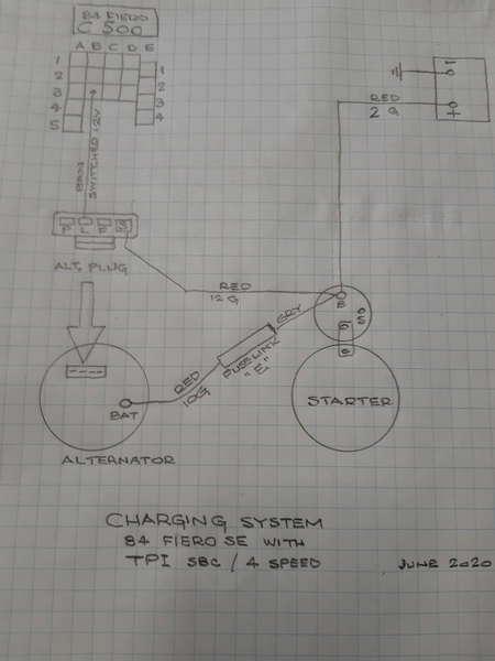
I had a chance to chase some wires this morning, even forfeited watching the NASCAR Truck race. Key off, I had 12v at the battery post, 12v at the at the starter's bat screw,12v at the "S" terminal, 0v at "F" (Yeah I know, read on) and "P" & "L" where not hooked up. Key-on-eng-off, Same except "F" has 12v. The schematic below is how I have it NOW. I'll explain what I found, I'm sure you already know.
Edited to delete wrong information, refer to 6-29-20 3:45 pm The alternator is a 91 f-body TPI Vin 8 or Vin F. The alternator plug has the wires colored this way. P - white L - brown with red stripe F - brown S - red
Edited to delete the wrong information about the alternator
What I found was, I attached the "F" terminal of the plug to the C500 "B3". I was actually glad because all the info I read, I should have connected the "L" terminal to the C500 "B3". I figured there's my problem. After checking the wires, key-off, "P" & "F" not connected, 12v at "S" and 0v at "L". Key-on-eng-off, 12v at "S" and "L". Started the car and no charge. BTW - voltage gauge in the dash shows the battery voltage. The alternator has a solid bar attached from the ground bolt at the rear to the block for rigidity, so it's grounded good.
What else can I check other than pulling the alternator off to have it checked? Hate to do it because what used to take me an hour, now takes me all day. Thank you again.
Edited to add this - Did I fry the alternator's regulator by applying 12v to "F" terminal?
[This message has been edited by rubyredfiero (edited 06-29-2020).]
bottom Img is from what? Wires don't match is something wrong. You guessing won't help because several reg's for CS family and changes F or I for that pin...
Add many CS alts Do use S pin because the Reg don't wire to Alt Out term inside of the alt.
quote
Originally posted by rubyredfiero: Edited to add this - Did I fry the alternator's regulator by applying 12v to "F" terminal?
Even when reading them... Many New versions of "CS-130" and related the Regulator in them are:
Many to Most after ~ 95 CS-xxx have All Silicon Voltage Regulator (ASVR) and easily fry when wired wrong or doing electric work w/o disco the battery. see http://econtent.autozone.co...US/2/0/86/tt-661.pdf page 2
Some Old and Many ASVR reg's control by PCM and may never turn on w/o PCM. Likely because have a wire to P pin. And P may not be wired in bottom img. Likely need correct "Dumb" CS-130, CS-130D or whatever. Or change Regulator to the "Dumb" one if even possible for this one.
[This message has been edited by theogre (edited 06-28-2020).]
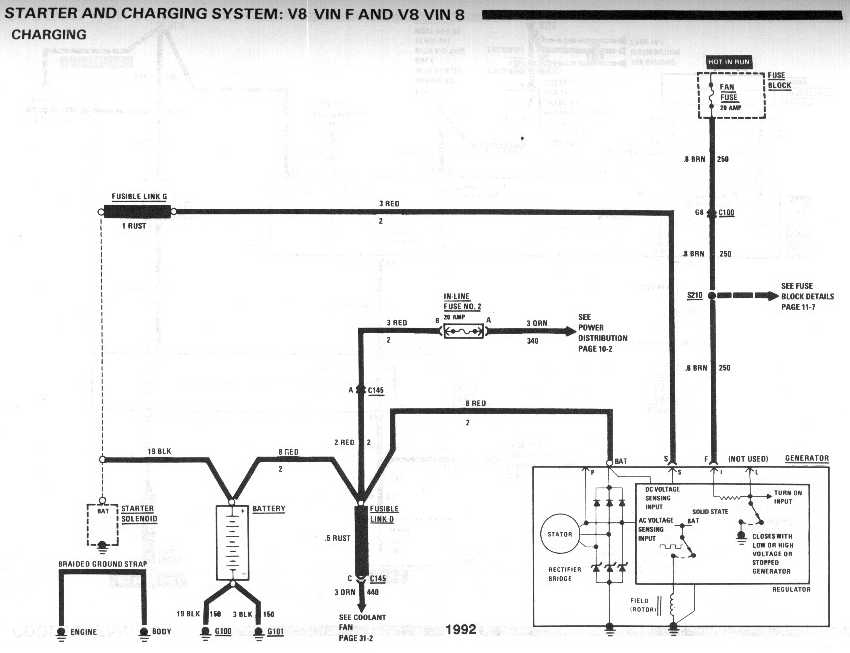
I made a MISTAKE by identifying the alternator as a 94 Impala LT-1. It's the belt tensioner that was LT-1. The alternator is a 1991 F-body (Camaro/Firebird) with TPI engine. Below is the proper schematic for the charging system.
I noticed that the f-body did not have a resister in the brown wire (circuit 250). Ogre - this make better sense now?
If you look at my post of 06-28-2020 01:56 PM, the only difference between my diagram and the f-body diagram is the brown wire goes from "L" on the alternator to "B3" of C500. I also noticed on the f-body diagram, the "F" brown wire is connected to switched 12v, which was my original connection before I moved it. So that should not have damaged the alternator. Still there is no charging. Battery stays at 12.52v and drops, even at 2500 rpm, no change in volts.
At this point is best is take the alt to AZ etc for "bench testing" on their machine. If is a early ASVR type can blow the reg easily. Not hard to kill them anyway even for old SI and "older" CS alts.
Note that CS alt's won't turn on when it sees a battery low. Think < ~ 11.5 maybe < ~ 11.75 Maybe higher if wiring is crap. CS is made to protect itself from a "dead" battery. Most won't turn on right after starting too. Waits some seconds to maybe a minute to turn on. If battery dies fast then take battery to test too. May have a "dead cell."
1992 drawing is "Version I" in CS page in Cave
If you look at plug parts... often labeled as F/I or I/F because that pin function is different for year/engine. Outside of alt in img's above list F but look right below is an I. The rest matches.
Test S pin to have "12v" w/ Key On. 12v to F/I pin should turn on w/ or w/o bulb circuit.
Note: Many GM shows Diode in lamp wiring but I've never actually seen one in the car. GM copy/past many parts to whole drawing and might not be their. Most times Diode fail open so won't get "12v" at the alt plug.
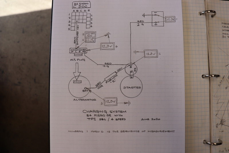
These are the readings I got at points 1 thru 6. I hope #6 is low because there's a resister in series. Based on the voltages, is it correct in stating the alternator must be pulled out? This is not going to be fun for this old guy, but it must be done.
12.3v and engine running? = alt Not running. Even wait a minute or three doing measurements still at 12.3v = alt is likely "dead." Running Alt should be 14 - 15 v at all 12.3 points. (Car w/ iffy wiring can jack alt out higher then 15 v because of big sense wire loop on 84 as covered in alt sense page.)
All meter grounds are on the engine or engine and frame? If both likely means major grounds are ok since most are same v.
L wire will have less v because v-drop for resistor wire at minimum.
check Ω between alt out and starter. FL can "blow" w/o Frying off because wire and splices break.
Carefully check the "side plug" to the alt. Many are damaged and alt have problems. Problem is it's a Metri-Pack "Pull to Seat" type and not easy to take apart and too small even then and likely wreck the pins getting them out. See my Cave, Weater/Metri Pack notes plus have a clip very hard to see or release the pins. So if it looks has damage, buy a pigtail and ignore I/F & P.
Metri-Pack "Pull to Seat" take apart should be covered in any FSM and others after ~ 87. Most don't bother trying even when have GM tools.
theogre - appreciate the input and will try to answer some of your concerns:
Lets Assume you have a good meter and probes... I use a digital power probe.
12.3v and engine running? Yes, after any mods the voltage only dropped slightly, never up. Went for a 15 minute run with voltage dropping to 11.75v.
All meter grounds are on the engine or engine and frame? Battery ground strap, 1" cradle strap and 6 ga chassis strap are attached to both cylinder heads. All the motor/trans mounts are solid steel.
check Ω between alt out and starter. The fuselink wire is about 20" long and it measures 0.00 ohms.
Carefully check the "side plug" to the alt. When I first switched the brown resister line from "F" to "L" and the result was still no charge, I replaced the connector with a new one which still gave me the same "no charge" condition. So now the alternator is out and today being CANADA DAY, I may disassemble it and check it using the FSM. BTW - it took this old guy 6 hrs to remove it, due to the serpentine setup that have to be all done from under the car. But it's out.
No charging condition SOLVED. I hope other peeps use this thread in the future, because I sure learned a lot from all the input provided. OK, OK. The alternator was the culprit, to be more specific, the voltage regulator had internal failure. This time it only took me 3 hrs to install the new alternator. That's twice as fast as taking it off.
So thank you all for the input. Too bad we can't edit the heading to add the word "SOLVED", or I don't know how to do it.
[This message has been edited by rubyredfiero (edited 07-02-2020).]