I tested my instrument cluster with new LEDs before actually mounting it back in place. Everything worked fine. I bolted everything up and put the connectors back on. Now my coolant temp light quit working and I am getting a weird sound when I start the car. I am pretty sure one or more of the connector contacts got shoved around when I put the connectors back on.
Right now, one false move with the connectors and the contacts get bent. I was thinking of taking it all apart, straightening out the contacts and using mounting tape to hold the contacts in place.
Question.. would a recreation of the flexible conductor panel, complete and ready to replace the original, be of real value? It can be done, but probably expensive enough to require at least many dozens to be made to make it worth it. Is it?
Question.. would a recreation of the flexible conductor panel, complete and ready to replace the original, be of real value? It can be done, but probably expensive enough to require at least many dozens to be made to make it worth it. Is it?
I don't think it would be that bad.
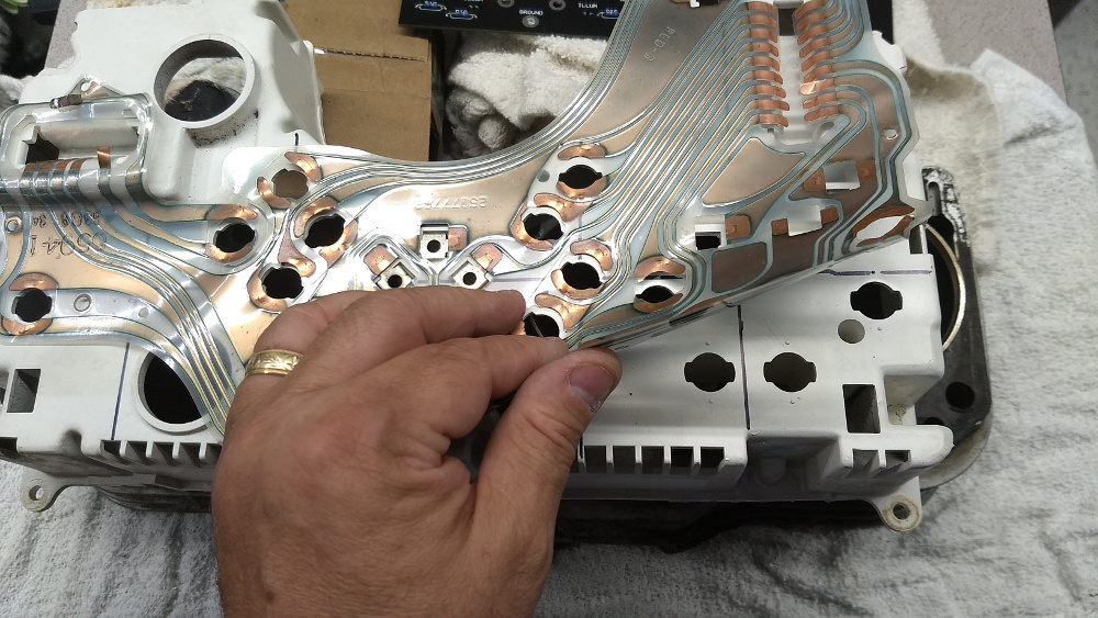
Board is single-layer IIRC, so it should be simple enough to lay flat on a scanner, then digitize, import into CAD program, and draw traces to generate Gerber files.
I entered the following parameters for a quick online quote: Flexible PCB 1 layer 200 mm x 350 mm Immersion tin (all other parameters left at default values)
Qty 1: 137 USD Qty 5: 53.8 USD each Qty 20: 37.1 USD each
Right now I would love a solution that would guarantee I had a good connection at the connectors. I am fighting a slight flicker as I turn the key to the START position. Not sure if it is a marginal connection or if it is just the fact the new LED bulbs react much quicker to changes in voltage as compared to their incandescent counterparts. Prior to fully assembling I installed the instrument cluster alone. I could swear all responded like the incandescents, but I am beginning to question my memory..
There are minor different versions of the board over years of Fiero. Example: Some actually have contacts for 1 or 2 "spare" bulbs hidden by front of dash. (2 blank slots above the tach lights.) The big plugs just isn't wired to use them. 84 Dash may have more changes the others.
Worse Most to all FSM and other docs are wrong what plugging into it like most/all is missing 2 "dimmer lights" lights to light fuel and temp gauges w/ HL on. See https://www.fiero.nl/forum/F.../HTML/138175.html#p1 So can't trust data there.
"Board" is single layer but w/ plastic over the copper too. Is done to protect the copper and prevent shorts. Replacement "boards" can have same problems of OE boards or worse. Many Fiero dash trim are missing foam to block UV from sun. Many plastics and "glue" won't last long when true. OE dash gets baked and UV and other pollution to deal with and it's a wonder last so long w/ only minor problems.
Another problem is the plastic "board" and dash case can "compress" over years and part of many bulb sockets have problems even when the sockets are replaced w/ new ones. If you just slap a new board over old case then could have problems very soon as new board conforms to old case plastic.
I think OE "board" copper is thicker then normal. Maybe 2x or 3x the thickness of most others even flex "boards." Is why can survive "bad glue" for the big plugs. "old way" to spec a board copper is X oz copper per 1 sq/ft... (or maybe 1 sq/yd not digging thru my notes...) most standard boards are 1oz or less. Might be this is 1.5 to 2 oz. Maybe up to 3oz.
Board base plastic is thinker too then nearly any others flex boards I seen in 40+ years of dealing with them. Between case plastic, thick board plastic and copper all adds to make clearance etc for bulb sockets and other parts to fit right.
------------------ Dr. Ian Malcolm: Yeah, but your scientists were so preoccupied with whether or not they could, they didn't stop to think if they should. (Jurassic Park)
I knew that The Ogre would know.. How about making a rigid (normal 1/16" 2 sided) PC board with appropriate hardware to fit.. and then use sockets with wire leads that connect to the board. I have done many lamp boards for other projects, even designs with ultra bright 5mm LED's on the PC board.. lots of options there. I suspect that the key reason for the flex board was the uneven surfaces plus lower cost.. a standard PC board would be a very solid fix for intermittent problems. The existing press mate connectors would have to go.. probably crimp and poke some other type of connector to replace the existing ones. Not a reversible process. Although it MIGHT be possible to put the contacts in for the press mate style.. the copper would go around the lip of the rectangular hole in the board, castelated style.. MIGHT be possible. Think of the upgrade possibilities!
There are minor different versions of the board over years of Fiero. Example: Some actually have contacts for 1 or 2 "spare" bulbs hidden by front of dash. (2 blank slots above the tach lights.) The big plugs just isn't wired to use them. 84 Dash may have more changes the others.
There are lots of small variations over the years, but as far as I can tell they are all cleverly interchangeable. I have disassembled dozens of them and never had a problem randomly using circuit boards from one cluster on another.
Originally posted by Chris Eddy: I knew that The Ogre would know.. How about making a rigid (normal 1/16" 2 sided) PC board with appropriate hardware to fit.. and then use sockets with wire leads that connect to the board. I have done many lamp boards for other projects, even designs with ultra bright 5mm LED's on the PC board.. lots of options there. I suspect that the key reason for the flex board was the uneven surfaces plus lower cost.. a standard PC board would be a very solid fix for intermittent problems. The existing press mate connectors would have to go.. probably crimp and poke some other type of connector to replace the existing ones. Not a reversible process. Although it MIGHT be possible to put the contacts in for the press mate style.. the copper would go around the lip of the rectangular hole in the board, castelated style.. MIGHT be possible. Think of the upgrade possibilities!
Few if any would buy something like that to fix a dash w/ OE gauges etc. Some might buy a complete "upgrade" but would cost money few have.
Think... Take a dash completely apart and really look at how many things to connect w/ new connections. Tach w/ OP uses clips that are push into the board and back to clip the tach board bolts. 6 more for temp/fuel gauge set. The clips just "floats" in the holes and ears are bent on back to make contact w/ the board copper.
Is not like Dash Lights sockets are made for PC use. Back plastic and board ~ = to standard FR4 board. Other cars and more has same type sockets on full rigid boards. And Size for 194 bulb isn't only size but that's very common and used in millions of cars of many brands.
The OE "board" was not cheap to make and GM wasn't only company using same setup. The setup goes back to at lest the 70's and likely 60's. (The plastic "film" over the id10t lights, backlit gauges, etc. were not cheap to make either.)
Yes, China board makers and others make flex boards but isn't same type of thing and likely won't last long in a car dash. OE board and copper is made to last even w/ nubes and worse changing the bulbs. The Fact you can "simply" re-glue the copper when has plug problems should tell any that designs board the copper is far thicker then normal. Even thicker then boards for ECM Radio and many more made same time.
Again, LEDs often has issues/problems for cars did have them from the start... Like Dash dimmer often doesn't play well w/ them. Is not simple looking in FSM etc because those don't follow real true wiring for them. Of the very few that take time to find real wiring... 99.9+% miss the fact GM and others use NPN Power Trans on + side of the dash bulbs and Doesn't have resistor on Base of that trans too. And no, that base resistor is Not hidden inside of Knob/wheel or trans socket. Is simply not there. Go to nearly any "book" and most will tell you put NPN or N MOSFET in ground side yet GM and other was done the dimmer in a Nonstandard way w/o "required" Base resistor. Just look in cave dimmer page. Is likely a big part of Why doesn't play well w/ most LEDs. Possibly too many LEDs and resistor w/ them can "short out" the trans and fry the trans and the dimmer "wheel" for too many mA flowing thru the Base.
Originally posted by jscott1: There are lots of small variations over the years, but as far as I can tell they are all cleverly interchangeable. I have disassembled dozens of them and never had a problem randomly using circuit boards from one cluster on another.
Likely none where 84. 84 has same light for engine temp and OP and no OP gauge or back plane for one.
GT had dash wiring for tach w/ OP gauge but most didn't have a clip there to really use a "Duke Tach."
[QUOTE]Originally posted by jscott1: There are lots of small variations over the years, but as far as I can tell they are all cleverly interchangeable. I have disassembled dozens of them and never had a problem randomly using circuit boards from one cluster on another.
Likely none where 84. 84 has same light for engine temp and OP and no OP gauge or back plane for one.
GT had dash wiring for tach w/ OP gauge but most didn't have a clip there to really use a "Duke Tach." [/QUOTE]
Yes I have used 84 circuit boards and they are cleverly interchangeable. Just like the intermittent wipers and the regular ones use the exact same harness.
The circuit boards do different things with certain traces but they are still interchangeable.
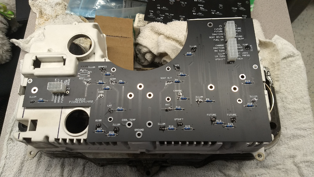
My first version of a rigid replacement circuit board is here and I did some fitment and testing. I believe that the idea will work and be reliable. The biggest unknown is how bright the backlight will be, which must be at least as bright as the original. And whether it dims well or not. The hard part was that the tach and double gauge modules plug into the clips. I could not easily add clips. So 6-32 x 1/2" FF standoffs are screwed onto the gauges, and inserted.. a screw fastens each point from behind. Honestly, once you get the original IC apart, it goes back together pretty quick. I added Mini-Fit Jr connectors to the PC board. Probably the easiest plan is to make the mating connectors with 4" of wire and butt splices to join to the original wiring. Sorry, I could not keep the original connectors as I cannot figure out how to mate to them. I have also been working with Cajun on the Riviera IC interface board, and want to get it finished before I keep going with this project. Once that is done, I will make a revised FRICB (Fiero Replacement Instrument Cluster Board) made. I will also have to work out what the difference is with the other original version, which I do not have on hand. I made the FRICB to match my car, an 87 2M4 2.5.
It has been a while. I solved my problem and wanted to come back to explain so I may help someone else.
The flicker I spoke of was nothing more than the difference between how LEDs react to power turning on and off vs incandescent. As you turn the key to the START position there is a big voltage draw as the starter kicks off. With incandescent bulbs you see a slight dimming in the idiot lights when the starter begins turning. With LED the reaction is more instantaneous. Instead of a dimming it is more like a flicker.
Everything is back together and working fine. LEDs have really brightened up the dash. Not so tired looking (dim) anymore.
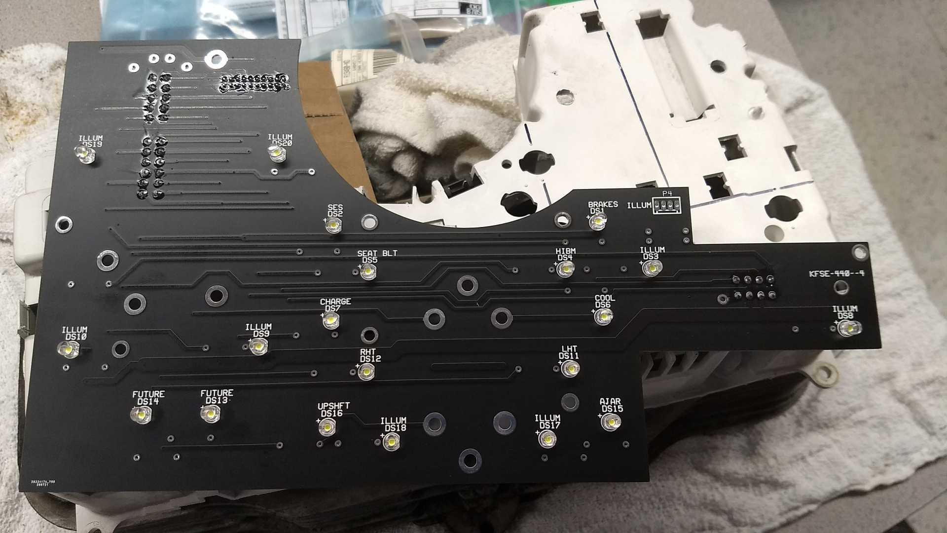
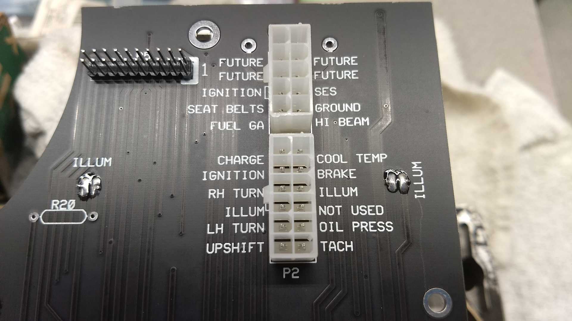
An update, I proposed a rigid PC board to replace the flex, and I think that I am getting somewhere. This is, BTW, designed for my little 2M4. I do not know what differences there are for the GT. Pictures.. This is the original flexible circuit over the back of the plastic bucket for reference. This is the PC board as it would sit on the back (there are two versions here for the eagle eyed). This is the PC board flipped over to show the bright white LEDs that I chose for this.. This is a closeup of two of the connectors, and the header is meant to plug in a test pod to measure things in car.. This is a closeup of the other connector on the other end. The revised board fixed subtle dimension issues, and beefed up pads for better solder joints. The key to this was the plug in gauges. The spring loaded contacts are not going to work with this. So I put standoffs on the end of the studs on the gauge, and then a screw through the PC board attaches. I have higher wattage resistors on the way, then can complete it, and do a very first test of LED brightness, and probably more important, if they dim easily and well. My goal is to have a brighter backlight than before, and I added two LEDs for that.. two holes have to be drilled for them. But there were no other easy to place locations for more backlighting. Once I get things finished, and test functionality, I will share some videos.
[This message has been edited by Chris Eddy (edited 08-04-2020).]
This was one of my projects, if anyone is skilled at circuits and PCB design, I would be happy to release the design into your hands. If anyone wants to reach me just do email, ceddy@nb.net.
i have gotten these files and will be using my spare 84 and 87 and 88 clusters to make some functional prototypes and modify as needed for a few custom projects (namely a LCD cluster that looks like a corvette one) thanks to chris for sending them over as im going to start work in my garage to etch a protype as soon as possible and test it for at least 3 months of use before i send any others out into the wild
im about halfway through modeling the v6 stuff and there is a few slight differences but not really. the real difference is i may be missing a pin on my tach or thats a I4 specific part, i dont have any of those tachs sitting infront of me to compare quite yet. when i get these boards out im going to try to make some way to reflect the light correctly into a non backlit cluster so its brighter than stock. i have a few ideas on that that dont require manual labor on the installers part (no offense to anyone but gotta make it take as little effort as possible since alot of people dont want to take the whole darn thing apart if they dont have to just to apply some tape) may also include some new foam strips for the gauges if i can find foam im happy with that isnt super expensive. the OG foam in my gt cluster was a high density urethane foam that is breaking down into rubber so i may end up trying some silicone strips