I'm having issues, suddenly, with my 88GT. Two of the sensors are reading lower voltage than they should. I have an AutoXRay scanner to see the sensor data in real time when I'm doing diagnostics. I had a code for TPS voltage high (code 21, I think) and the car ran like s***. Very rough running, stalling. I didn't see high voltage on the scanner. I replaced the TPS with brand new from Rock Auto. I got a sensor tester from eBay and tested it, no problems. Put it on the car, still running rough and now throws a code for TPS voltage LOW. On the scanner, it returns .19 volts at idle (code sets below .2v for more than 2 seconds) and .89v at WOT (well, at about 4000 rpm). It should be more than .2v and closer to 5v at high throttle. So now I'm thinking electrical issue, high resistance, alternator/regulator, etc.
The scanner shows system voltage seen by the ECM pretty steady (+/- .2v) at 14v. All other sensors (except MAP) appear to be in their proper operating range. The wiring connector or adjacent wiring might be worn or developing high resistance. I assume that could cause incorrect voltage? Is it possible there is a small enough problem with the ECM to cause two sensors to be out of range, but everything else is fine? Bad capacitor?
The MAP sensor tests good on the tester, and doesn't throw a code. But it is also not returning enough voltage to the ECM (doesn't throw a code). Tested with good used and a new part.
As far as ECMs go, it appears there are only 5 types of ECMs, 3 for 4 cylinder, and 2 for V6...
85........1226869 86-88...1227170
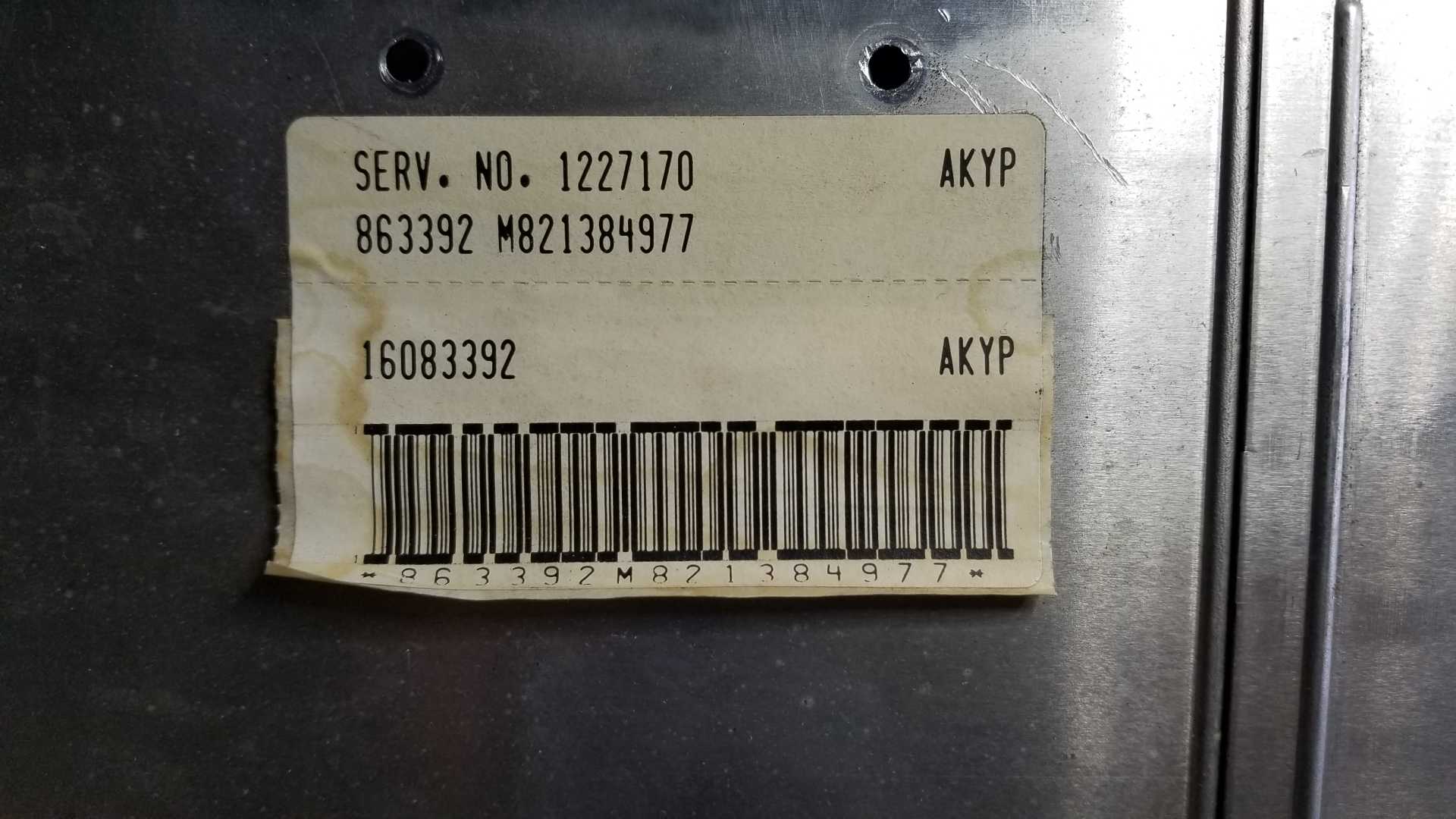
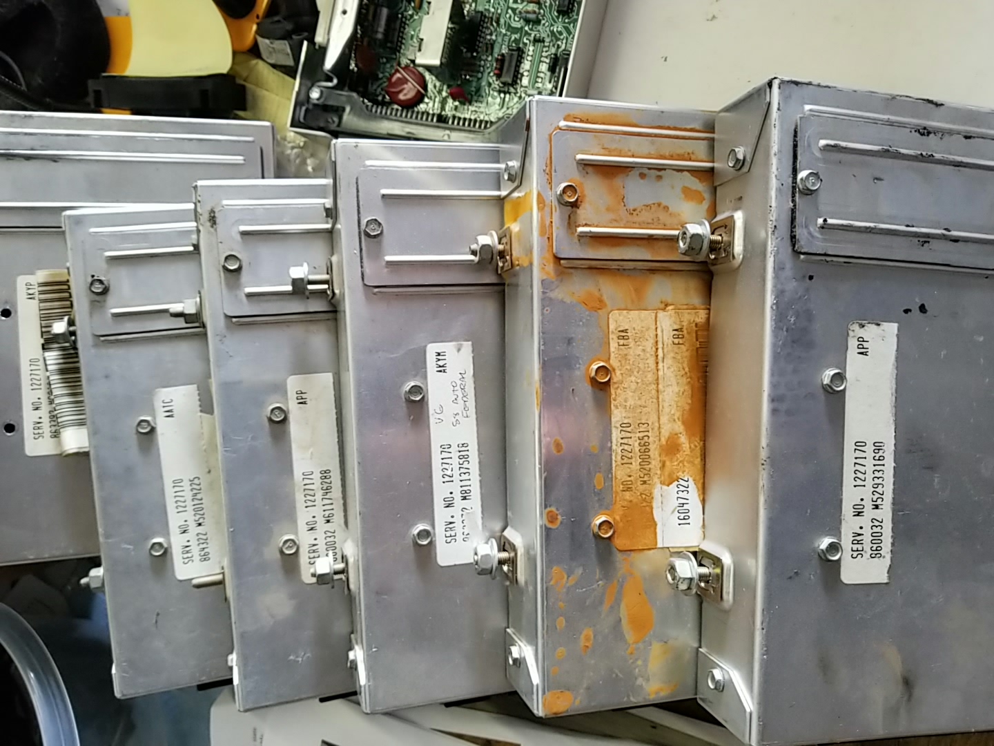
I have a stack of ECMs with part number 1227170, but there several other numbers and letter codes that are different. I had a note scribbled on one of them saying "federal", probably a different ECM for California? There are only two part numbers in the 22P book, with no difference between auto and manual transmissions? Is there an ECM application guide somewhere?
I'm having issues, suddenly, with my 88GT. Two of the sensors are reading lower voltage than they should. I have an AutoXRay scanner to see the sensor data in real time when I'm doing diagnostics. I had a code for TPS voltage high (code 21, I think) and the car ran like s***. Very rough running, stalling. I didn't see high voltage on the scanner. I replaced the TPS with brand new from Rock Auto. I got a sensor tester from eBay and tested it, no problems. Put it on the car, still running rough and now throws a code for TPS voltage LOW. On the scanner, it returns .19 volts at idle (code sets below .2v for more than 2 seconds) and .89v at WOT (well, at about 4000 rpm). It should be more than .2v and closer to 5v at high throttle. So now I'm thinking electrical issue, high resistance, alternator/regulator, etc.
The scanner shows system voltage seen by the ECM pretty steady (+/- .2v) at 14v. All other sensors (except MAP) appear to be in their proper operating range. The wiring connector or adjacent wiring might be worn or developing high resistance. I assume that could cause incorrect voltage? Is it possible there is a small enough problem with the ECM to cause two sensors to be out of range, but everything else is fine? Bad capacitor?
The MAP sensor tests good on the tester, and doesn't throw a code. But it is also not returning enough voltage to the ECM (doesn't throw a code). Tested with good used and a new part.
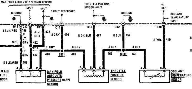
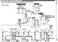
The first thing I would do is put a multimeter on the sensors and see if you have the full +5v at the sensors. If you've got a failed regulator in the ECM, you might not have the full +5v out of the ECM. The next thing is to jump the signal circuit of each sensor to the +5v, and the sensor ground alternately, while monitoring your scantool data. If the ECM sees (and reports) +5v and 0v, your wiring is all good. I suspect you'll find you don't have the full +5v. The MAP and TPS are both fed by circuit 416, a gray wire out of C14 from the ECM.
I included the CTS in this pic to show that it is on a different +5v circuit out of the ECM. I don't know if there are more than one actual 5v regulator in the ECM, or if they all share a single regulator.
quote
Originally posted by fierobear:
As far as ECMs go, it appears there are only 5 types of ECMs, 3 for 4 cylinder, and 2 for V6...
85........1226869 86-88...1227170
I have a stack of ECMs with part number 1227170, but there several other numbers and letter codes that are different. I had a note scribbled on one of them saying "federal", probably a different ECM for California? There are only two part numbers in the 22P book, with no difference between auto and manual transmissions? Is there an ECM application guide somewhere?
The AKYP is the broadcast code for the PROM calibration. The part number 1227170 is for the computer itself, with no PROM. There are a VAST number of possible broadcast codes, with different calibrations for Auto vs Manual, Fed emissions vs California, 4.10 vs 3.65, and so on. I'm not aware of a compiled list for Fiero broadcast codes.
Multiple sensor w/ problems first check have 5v and/or ground from ECM. Check at sensors and at ECM because maybe iffy wires not iffy ECM. TPS etc have 5v and/or ground directly from ECM.
Sensor Ground wires to engine should be near zero volts and near zero Ω. Do Not use Ω meter on other ECM wires as most Ω meters can fry the ECM. 5v to sensor ground wires should be 5v ± 0.3v max. Do Not measure 5v to block/frame. Likely won't damage but have errors no matter how careful you test to block etc. (If you have a analog meter or Digital w/ Rel button is better. Both allow you to cancel Ω for probe wire etc.)
But watch ICM and O2 because the "grounds" for them are "fake Grounds" that only see why when have schematics and know what you're reading across several pages or worse across several documents. Do Not use Ω meter. ICM fake ground is in my Cave, Ground "Myth" notes O2 fake ground is tan wire to block where trans bell mounts.
Check/fix/clean all ground ends bolted to engine @ minimum. G202 too since have console out to look at ECM. Is on tunnel below ECM. Clean and coat w/ silicon or brake grease.
------------------ Dr. Ian Malcolm: Yeah, but your scientists were so preoccupied with whether or not they could, they didn't stop to think if they should. (Jurassic Park)
Is just 1 page of Ludis' site w/ a lot more then that. Site shut down or moved then died in last few years. Don't no if any have copies except archive.org and that's missing some pages/images
The conversation was regarding Fiero ECMs and broadcast codes. The other stuff on those pages seems to be non-Fiero - or just common to many other platforms.
In any event, maybe the tables will provide enough info to be useful.
[This message has been edited by Raydar (edited 02-23-2020).]
Excellent, thanks! I remembered Ludis’s page, but am surprised it was still up.
If that data is complete, the only transaxle ratio PROMS appear to be for early 4 speed transaxles.
All of the Isuzus and all of the Getrags only had one ratio option (in Fieros, I know the Isuzu could be had with a 4.11 final in some of the Geo applications).
Excellent, thanks! I remembered Ludis’s page, but am surprised it was still up.
If that data is complete, the only transaxle ratio PROMS appear to be for early 4 speed transaxles.
As Jimmy posted, all of the Fiero Getrags had the same FDR. And all of the V6 4 speeds had the same ratio. The only real variable was tire size, and that wouldn't likely affect any functionality. If anything, it probably affected the timing of the "upshift" light. Which is probably a big deal in California, considering how they are.
Edit - It would appear that all V6 automatic FDRs were either 3.06 or 3.33. 86s seem to have used both. I don't know if the ratio change had anything to do with model (SE vs GT) or if it was a running change done to all cars, after a certain date.
[This message has been edited by Raydar (edited 02-23-2020).]
Looking at the ECMs I have as spares (as seen in the picture up thread), the closest one I have is the APP ECM, for the 86-87 5-speed CA chip. I also have a 5 speed Formula sitting around, so I should be able to “borrow” that ECM for a simple test. My scanner shows the Formula sensors look more normal, although the TPS didn’t show voltage anywhere close to 5v at 4000rpm. I don’t think I’ve ever seen any of my Fieros show that much voltage.
Anyway, assuming for the moment that the 5v reference circuit in the current ECM is faulty, would the problem be only an internal failure of the ECM, or could the failure be caused by the wiring between the ECM and sensors?
The first thing I would do is put a multimeter on the sensors and see if you have the full +5v at the sensors. If you've got a failed regulator in the ECM, you might not have the full +5v out of the ECM. The next thing is to jump the signal circuit of each sensor to the +5v, and the sensor ground alternately, while monitoring your scantool data. If the ECM sees (and reports) +5v and 0v, your wiring is all good. I suspect you'll find you don't have the full +5v. The MAP and TPS are both fed by circuit 416, a gray wire out of C14 from the ECM.
This. Exactly this. When you said that two sensors were reading strange, in the same manner, I was thinking there would be a commonality. The circuit that Jimmy mentioned is that commonality. Of course, if you swap in your spare ECM, and the problem goes away, it would seem to point at that ECM, unless you have an intermittent wiring issue. But it still should be that same circuit.
If the ECM swap fixes it, and you want to retain your original chip, the chip (in its plastic carrier) can be unplugged and swapped from your original ECM to the replacement. (Do they actually check for that?)
Edit - Sorry. Any one of the "7170" ECMs will work, if you transfer your chip over to it. Or you can just leave the earlier 5 speed chip installed. It will also run your car just fine. Of course, if they actually check what's in the car, they're going to want it to have the 88 chip in it.
[This message has been edited by Raydar (edited 02-24-2020).]
This. Exactly this. When you said that two sensors were reading strange, in the same manner, I was thinking there would be a commonality. The circuit that Jimmy mentioned is that commonality. Of course, if you swap in your spare ECM, and the problem goes away, it would seem to point at that ECM, unless you have an intermittent wiring issue. But it still should be that same circuit.
If the ECM swap fixes it, and you want to retain your original chip, the chip (in its plastic carrier) can be unplugged and swapped from your original ECM to the replacement. (Do they actually check for that?)
Edit - Sorry. Any one of the "7170" ECMs will work, if you transfer your chip over to it. Or you can just leave the earlier 5 speed chip installed. It will also run your car just fine. Of course, if they actually check what's in the car, they're going to want it to have the 88 chip in it.
No, they don’t check the actual chip. The only issue for California smog would likely be the CA chip versus the federal chip and how that would affect emissions.
I’ll run the wiring test first before ECM swap, if applicable.
I checked voltage to ECM ground on both the TPS and MAP sensors. Both are showing 5v. The engine seemed to run better with the TPS connector disconnected, and the idle was higher (but not way high).
I’m baffled.
[This message has been edited by fierobear (edited 02-24-2020).]
Odd. I might suggest a ground issue, but there is not a common ground. The MAP grounds through D13. The TPS and the CTS both ground through D12. Unless both pins are connected internally, and both are broken from the ECM ground. Does the scan tool indicate a realistic coolant temp? (You may have mentioned that already.)
Edit - Did you measure the 5V with the sensors connected?
[This message has been edited by Raydar (edited 02-24-2020).]
Odd. I might suggest a ground issue, but there is not a common ground. The MAP grounds through D13. The TPS and the CTS both ground through D12. Unless both pins are connected internally, and both are broken from the ECM ground. Does the scan tool indicate a realistic coolant temp? (You may have mentioned that already.)
CTS shows correct temperature.
I managed to get the engine started and kept running, with the TPS and MAP sensors disconnected, long enough to do the resistance tests. At the 20M setting on my DVM, both sensor plugs showed about .2 ohms from sensor to ECM ground. I wasn’t able to rig pins into the wires or weather pack and get contact.
Edit - Did you measure the 5V with the sensors connected?
I wasn’t able to get contact with the connectors on the sensors. With the plugs off, both showed 5v. When I jumpered 5v to sensor, the scanner showed 5v or 4.99v.
I wasn’t able to get contact with the connectors on the sensors. With the plugs off, both showed 5v. When I jumpered 5v to sensor, the scanner showed 5v or 4.99v.
Sounds like you may have been measuring "open circuit" or un-terminated voltage. At this point I would just go ahead and switch ECMs.
OR...plug everything back in, and measure the 5V at the ECM connector. Gently stick a straight pin or paper clip into the back of the ECM connector, alongside the wire. IF you can get to it.
I swapped ECMs with the Formula, got pretty much the same voltage readings on the TPS on the scanner. I have a set of DVM probes with penetrating needles, but the results were inconclusive. There was some rust on them, so they are being soaked in vinegar and will recheck when they are clean. But so far, it is pointing to wiring. Resistance is probably high.
[This message has been edited by fierobear (edited 02-25-2020).]
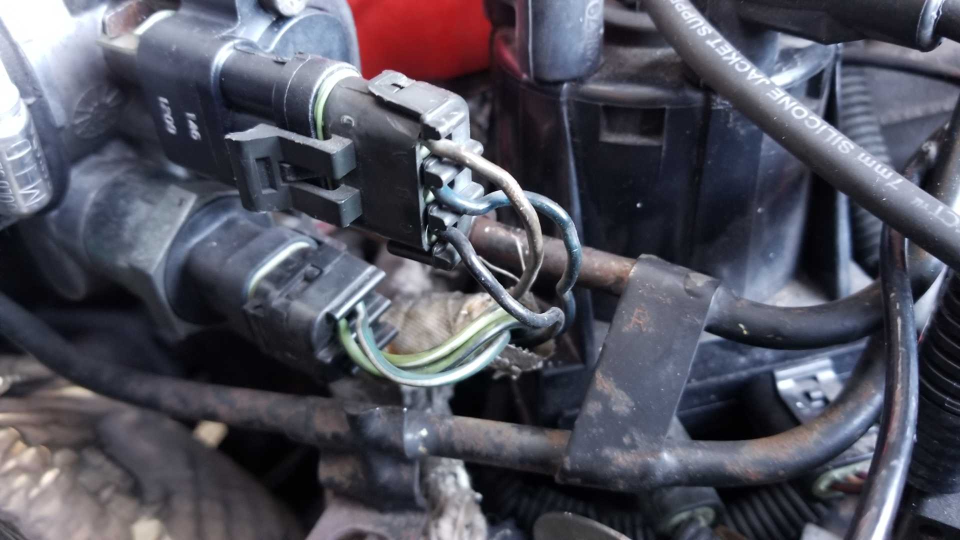
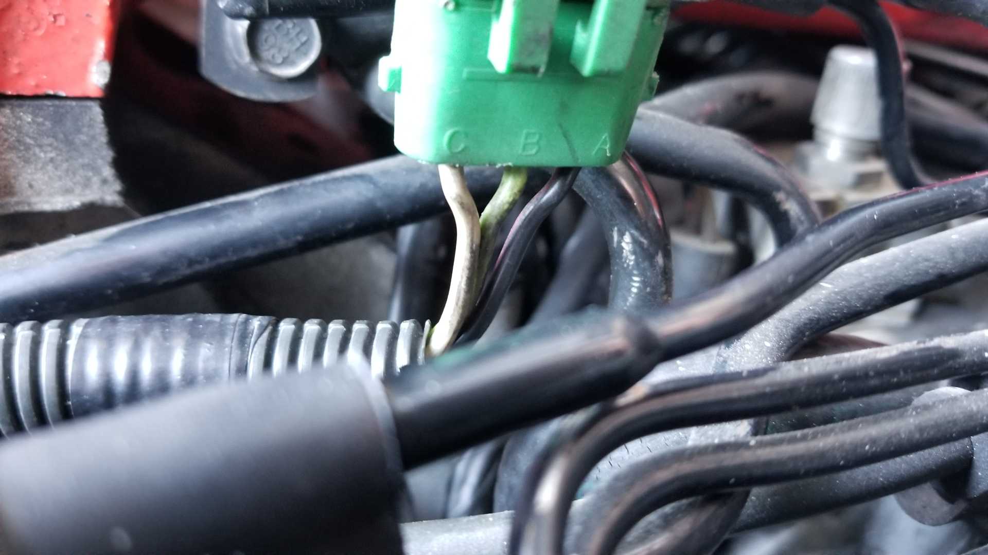
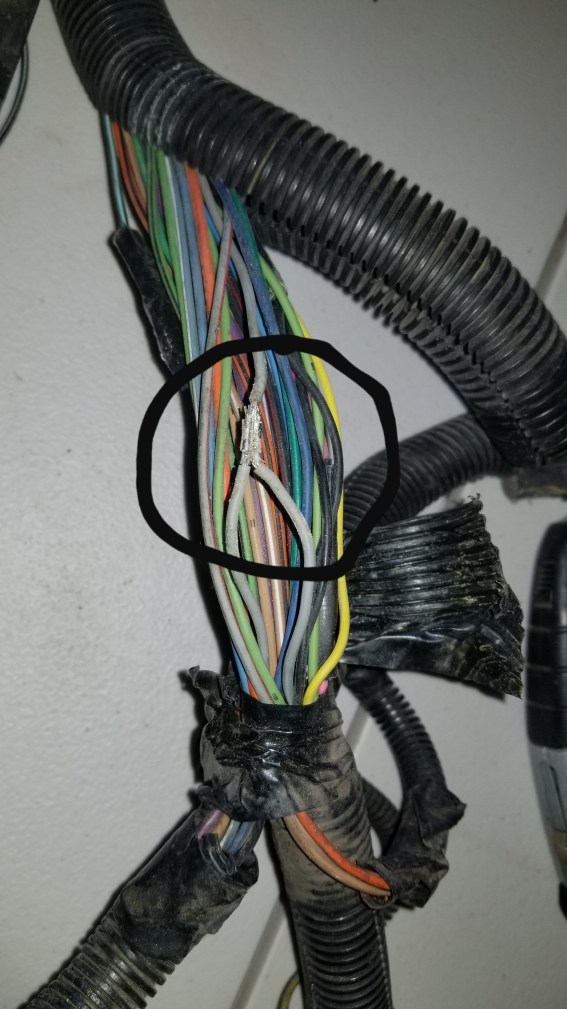
This is what the wiring looks like at it enters the connectors. Maybe they are in rough shape?
Assuming the connectors/wires are the problem, TFS has the TPS connectors for $19.95, Rock Auto has cheaper ones for $6.64 and AC Delco for $16.58. Is there any real difference, or is it worth the higher price for AC Delco?
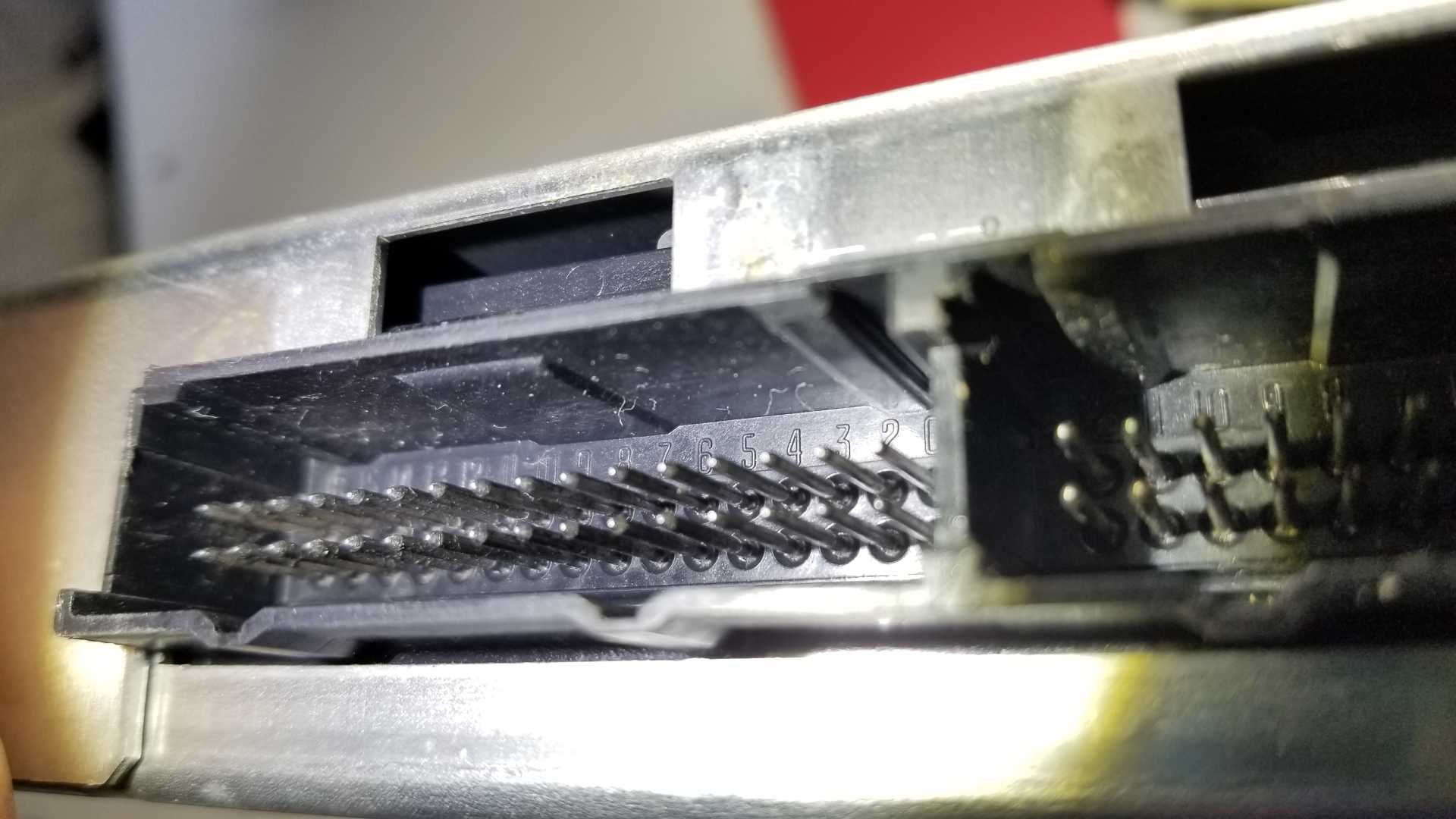
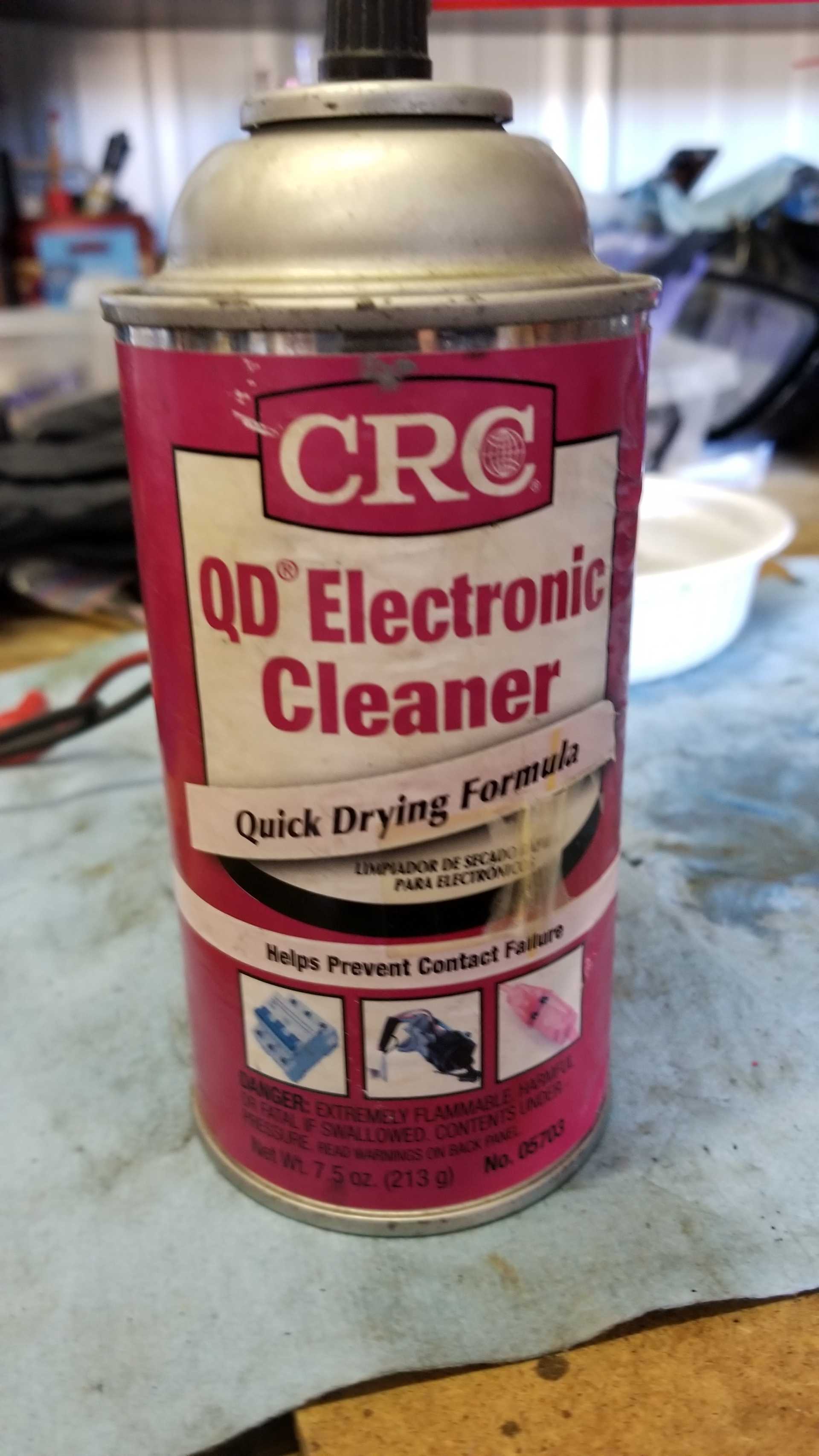
Looking at the pins on the ECM, there seems to be some slight build up of corrosion. I used some of the connector cleaner in pic 2, and a plastic bristle brush, but it doesn't seem to be doing the job. Any suggestions on a better cleaning method?
One thing I need to point out, is that this was a sudden change in the car's performance. I'd been driving this car for at least a year and a half after restoration, without even a hiccup. I drove cross town about 10 minutes, at 55-60mph, stopped for 10-15 minutes, and when I started the engine it was immediately running like s*** and has ever since. This suggests to me that corrosion on pins or wires wouldn't cause a sudden and ongoing issue like this.
Originally posted by fierobear: ... This suggests to me that corrosion on pins or wires wouldn't cause a sudden and ongoing issue like this.
I would tend to agree. The pictures of the sensor connectors that you posted earlier... Those really don't look too bad. I have seen way uglier wires that worked just fine, although that really doesn't mean anything.
I might try to check that gray wire that supplies the 5 volts. The best way to do it is if you can get a meter probe into the connector, alongside the wire, to make the measurements. Maybe tug on the wires and pins carefully, to make sure nothing is broken inside the plastic connector shell. Maybe it got pinched, or burned, somewhere along the way. I forget how it's routed, but if has to be one of the longer wires in the harness. (This, of course, is a complete crap-shoot, but nothing else is making much sense, either.)
Edit - Wait... Unless there are two gray wires crimped into the connector at the ECM, that 5 V wire splits off in two different directions, somewhere in the harness, to feed two sensors that are on opposite ends of the plenum. There has to be a solder joint or a crimp somewhere. That would be a place to look. Of course, it's gonna be a lot of fun chasing it through the harness.
[This message has been edited by Raydar (edited 02-25-2020).]
You almost always have Splices in the harness because GM and most others only crimp 1 wire in 1 end for 90+% of times because most Terminals and their Shells only accept 1 wire. Examples:
Read my post above... All 3 wire ECM sensors have 5v and Ground from ECM. Either/both are iffy then 1 or more sensors will have problems. Two wires sensor like engine coolant temp are part of "voltage divider" etc in the ECM and 1 wire here is mostly grounds.
Splices rarely die but if "water" gets into the harness will eat the copper right near them. Water will wick thru any weak weak spot and eat the copper faster then the solder section.
Might test the wire w/ Ω meter but: 1. Disconnect the wire from ECM and any sensors. 2. May don't help unless wire is really bad. 3. Really need an analog meter or Digital w/ Rel button to Zero out the probes. More so if you run long probe wires to test w/o pulling ECM plug thru the firewall.
[This message has been edited by theogre (edited 02-25-2020).]
I'd de-pin the TPS and MAP connectors to have a look at the terminals. De-pinning is a fully reversible operation; when you're done looking, you can put things back as they were.
You can use a Weather-Pack depinning tool such as Aptiv 12014012. It's available at https://www.mouser.com/
With the terminals removed from the plastic connector shell, you can: -Look at the terminals -Plug them into the sensors and start the car, allowing for easy probing while the car is running. -Wirebrush the terminals clean -Crimp new replacement terminals onto the original wires -Change the old crusty plastic connector shell.
If you want to buy individual parts (terminals, shells, etc), I have the Aptiv (ex-Delphi) part numbers available if you're interested. A complete pigtail is an option, but it has the disadvantages of introducing new splices into the harness (new points of failure), the harness becomes lumpy, and you'll probably have to mess with the stock wire loom.
The ECM pins don't look too bad, but that's my uninformed opinion... essentially hogwash.
I took a crash course (a few days long, so just enough to get a glance on the subject) on electrical contacts, and our teacher showed up graphs of contact resistance barely changing for a long time, and then all of a sudden shooting up. So I wouldn't discount connector corrosion as the cause of your problems because they appeared all of a sudden.
quote
Originally posted by Raydar: Edit - Wait... Unless there are two gray wires crimped into the connector at the ECM, that 5 V wire splits off in two different directions, somewhere in the harness, to feed two sensors that are on opposite ends of the plenum. There has to be a solder joint or a crimp somewhere. That would be a place to look. Of course, it's gonna be a lot of fun chasing it through the harness.
It's a crimp splice (S511) with tape over it, and IIRC it's in the main fat wire bundle near the location of the oil pressure sending unit.
There are also splices connecting the signal grounds together (MAP/MAT together, and CTS/TPS together).
Edit: see wiring diagram in FieroJimmy's first post in this thread.
[This message has been edited by pmbrunelle (edited 02-25-2020).]
Splices rarely die but if "water" gets into the harness will eat the copper right near them. Water will wick thru any weak weak spot and eat the copper faster then the solder section.
I was thinking more along the lines of a mechanical failure, or a heat or abrasion related failure. (Burned or "chafed" wire. Maybe a high resistance short to ground, like the edge of a shield or something.) But I hadn't even considered moisture. That's a good idea.
[This message has been edited by Raydar (edited 02-25-2020).]
Even w/ weather pack pin tool... ears can get pushed in and may not hold. Can Carefully pry out the ears a little so will hold again.
Can get Weather pack tools at amazon and more likely faster and free shipping then Mouser. Might get ends to but many are cheap copies so be careful w/ them.
Note: Tools and ends may not fit right because of tolerance problems so don't force them. Worse is ends have damage from people beating the hell out of them.
Is likely not the problem here but checking them won't hurt.
Originally posted by Raydar: I was thinking more along the lines of a mechanical failure, or a heat or abrasion related failure. (Burned or "chafed" wire. Maybe a high resistance short to ground, like the edge of a shield or something.) But I hadn't even considered moisture. That's a good idea.
Splices rarely die for mechanical problems too. Even new copper will break near the splice before the joint fails nearly every time. Is like wood etc often fails before proper glue joint fails.
Plus GM uses a lot of tape on the splices to avoid cutting other wires etc. "Water" oil etc can loosen or wreck the adhesive and will still try to do the job.
Now if you have exhaust leak(s), too close to exhaust, something pinch/pull harness, etc... Can cause this and Far Worse depending just what circuits have melted/worn insulation.
Example: Bad motor/trans mounts can yank the harness and hoses.
[This message has been edited by theogre (edited 02-25-2020).]
It is unlikely that water is the culprit in this situation because:
1. The day of the sudden failure was dry, no rain. 2. Since I completed the restoration of this car, it stays indoors all the time. I don't drive it in the rain or even park it outside over night, so no dew on it. 3. I don't wash the car with water/soap since the restoration/repaint. I only use detailing sprays and dri-wash polymer.
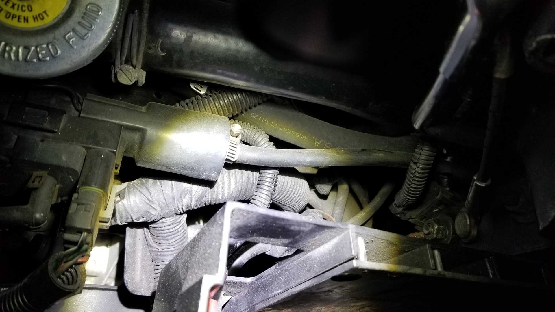
Updates: I have a spare V6 engine wiring harness that was in a box. I was able to located the splice we were talking about, circled below:
Based on examination of the location on the spare harness, I figure that the splice is located below and to the right of the EGR Solenoid:
It's going to be a ***** to get to, but before I start tearing things apart, there is something else I discovered. Just for the hell of it, I decided to move the metal arm on the TPS with my hand while the engine was running and my scanner was hooked up. Recall that I'd never seen anywhere close to 5v on the scanner from the TPS during normal operation. Not even on cars that aren't throwing a code or running badly. When moving the TPS arm all the way through it's travel range, The voltage when up to 5v! This is with the sensor connected, of course. So I'm wondering if we are actually getting full and proper travel out of the TPS metal arm by the throttle pushing it? Is it possible that something has gotten out of adjustment or worn out (like the spring on the throttle assembly) over time such that we aren't getting proper travel range on the TPS? This might not explain the sudden rough running, unless something mechanically broke.
Another test I did was to swap ECMs from the red Forumla, which is running well, to the GT. No change in any readings or running. I think we can rule out an ECM problem, and with my manual test of the TPS arm, it seems unlikely that the wiring is bad.
When installed in a car... TPS often never reaches 5v by turning throttle to WOT on TB/TBI by hand or by pedal. Close to same reason doesn't see 0v @ idle. Go by angle/% of throttle reported by a scan tool. Turn throttle by hand should see 99-100% @ WOT even when not seeing 5V on the scanner or on meter on sensor. But Press the pedal to floor often can't reach WOT because pedal and/or cable problems and more so for Fiero w/ 3-5 times cable length then front engines.
When installed in a car... TPS often never reaches 5v by turning throttle to WOT on TB/TBI by hand or by pedal. Close to same reason doesn't see 0v @ idle. Go by angle/% of throttle reported by a scan tool. Turn throttle by hand should see 99-100% @ WOT even when not seeing 5V on the scanner or on meter on sensor. But Press the pedal to floor often can't reach WOT because pedal and/or cable problems and more so for Fiero w/ 3-5 times cable length then front engines.
The voltage readings I'm getting are .19v at idle to about .89v at 4,000 rpm. The SM says a code will be set below .2v (which does happen), and at idle voltage should be below 1.25v. But it isn't clear what reasonable normal range I should expect to see, idle to near WOT (I won't go WOT with the engine running)?
I had a suggestion from a fellow Fiero guy (Keith, the tail light guy) that I might have water in the gasoline. Initially, the car wouldn't stay running on the day of the incident. When I went to start it some days later, it started up and ran well enough that I could move the car. I'm wondering if I got some contaminated fuel, and the water is mixing and settling. Is there any fuel additive that would help ingest the water, or if after getting a sample of the fuel should I just drop the tank?
[This message has been edited by fierobear (edited 03-14-2020).]
Originally posted by fierobear: ... Is there any fuel additive that would help ingest the water, or if after getting a sample of the fuel should I just drop the tank?
I have heard that alcohol will tend to absorb water. I believe that's why E-10 - E-15 gum things up so badly when they're left to sit for a prolonged period. With all of that said, there is a product called Drygas that may help.
Originally posted by fierobear: The voltage readings I'm getting are .19v at idle to about .89v at 4,000 rpm. The SM says a code will be set below .2v (which does happen), and at idle voltage should be below 1.25v. But it isn't clear what reasonable normal range I should expect to see, idle to near WOT (I won't go WOT with the engine running)?
I had a suggestion from a fellow Fiero guy (Keith, the tail light guy) that I might have water in the gasoline. Initially, the car wouldn't stay running on the day of the incident. When I went to start it some days later, it started up and ran well enough that I could move the car. I'm wondering if I got some contaminated fuel, and the water is mixing and settling. Is there any fuel additive that would help ingest the water, or if after getting a sample of the fuel should I just drop the tank?
Key on but engine not running will run ECM and test nearly all sensors so can test TPS at WOT w/o wasting gas etc.
Low volt at idle can be iffy sensor etc plus iffy idle stop setup. But can't check/reset the stop screw on engine w/ other problems. A SHORT TERM "fix" is make a thin shim to idle stop screw tip to bump idle volts barely above the minimum TPS volts.
idle stop screw etc can wear and make low volts and bad idle. Worn throttle parts can leak more air thru shaft holes, close butterfly too much, Stop screw digs a hole in the lever or tip wears or both, etc. (Most T-shaft clearance are made loose and leak a bit of air normally. Is a problem when you see Oval shape holes.)
If you have enough water the pump will suck it then very likely no additive, including any formula "Drygas," will help. Depending on label... "Drygas" is either Methanol or Isopropanol and using more then 1 small bottle in a car w/ full gas tank can cause bigger headaches because Both are Worse then Ethanol eating rubber parts etc. when used too much.
"Drygas" keeps small amount of water from freezing and blocking fuel lines etc. Car won't run if pump suck a lot of water even w/ "drygas" in the tank.
I was thinking about shimming the tps lever. I’ll give it a try. But, do you happen to know what the best voltage should be at idle?
[This message has been edited by fierobear (edited 03-14-2020).]
I was thinking about shimming the tps lever. I’ll give it a try. But, do you happen to know what the best voltage should be at idle?
If memory serves, there is a little "tang" that sticks out from the TPS sensor, that is pushed when the throttle is rotated to "open". If you bend that tang just a bit, in the right direction, it will cause the TPS to show a higher voltage.
If memory serves, there is a little "tang" that sticks out from the TPS sensor, that is pushed when the throttle is rotated to "open". If you bend that tang just a bit, in the right direction, it will cause the TPS to show a higher voltage.
I don't know if I'd be able to bend it enough, and it might cause a funky angle or for the tang to get caught on the throttle tang during it's travel. Might even cause damage to the sensor's internals. I'll probably just come up with a shim of some kind.
Fierobear, did the red Formula run properly after you reinstalled its ECM?
I haven't swapped them back yet. The Forumla has the GT ECM and vice versa. Formula is running well.
My next step is to do the above mentioned shim, but I'd like to get some idea as to a good starting/idle TPS voltage so that I can shim the tang to that point.
Bending TPS now isn't good either for same reason Not to reset Idle screw. Shim between throttle arm/lever and screw tip pushes idle a tiny bit to counter throttle wear etc Without being permanent or breaking the parts. Use 1 layer, maybe 2, of soda can sides is likely to bump idle enough.
You only need to bump so TPS is above min limit. ECM doesn't care if TPS is between idle limits. When w/in those limits the ECM should use IAC to "fine tune" actual idle. You will see this in IAC Steps Counts at idle in data stream to scanner. You also see Step Count change when engine running... AT cars will change counts just putting the trans in R or D then back for P/N. "In gear" the count can be 30-45 steps higher vs P/N count. Stick cars likely just drag the clutch a bit at idle when in gear. Should be instant change so drag the clutch to make engine to stall or heat/burn the clutch disk. Even a small manifold vac leak that you control can likely change Step Counts.
Ever w/o reseting IAC ECM will try to use IAC to set idle but may not report step count until ECM has reset iac driving > 35mph etc. Or Step Count reported aren't accurate until then. ECM report IAC Reset in the data stream too.
I haven't swapped them back yet. The Forumla has the GT ECM and vice versa. Formula is running well.
My next step is to do the above mentioned shim, but I'd like to get some idea as to a good starting/idle TPS voltage so that I can shim the tang to that point.
The reason I ask is what if the GT has broken its ECM. You might then swap in a known good one from the Formula only to break it as well. If the Formula’s ECM works when reinstalled, you could then test the GT’s ECM in the Formula.