I had read on the forums many reasons why a linear motor would not work on the fiero headlights and being the contrary person I am, I decided to give it a try.
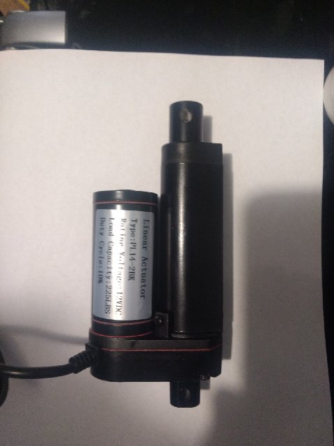
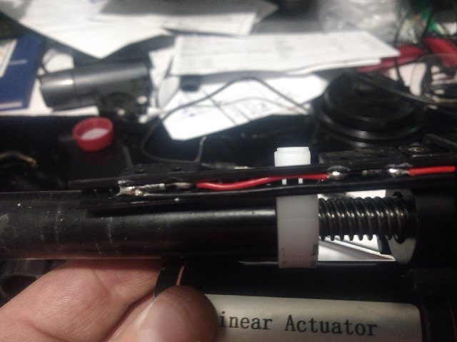
I purchased the following unit on Amazon for $38.00 with no shipping cost. Here is the link https://www.amazon.com/gp/p...02_s00?ie=UTF8&psc=1 It is a 2" stroke motor with up to 225 lbs force. In the size/stroke needed to fit in the existing area, I could find 5Lb or 225 lb actuators for a reasonable price. The actuator has "non-adjustable" limit switches built into the actuator that cut power at the end of each stroke direction. (they are adjustable if you can use a soldering iron)
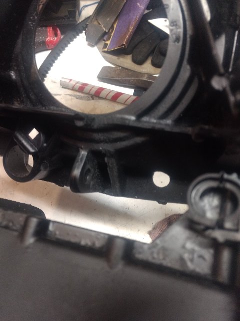
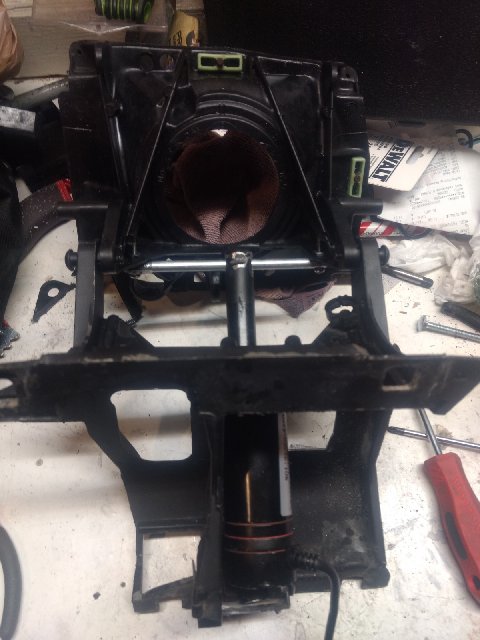
Some modification was required to the headlight assembly. I had to remove one ear where the original swing arm was attached for clearance. I left the other in place in case I need to go back to the original design.
I also had to add a 5/16" rod 1" from the hinge point across the moveable part of the assembly.
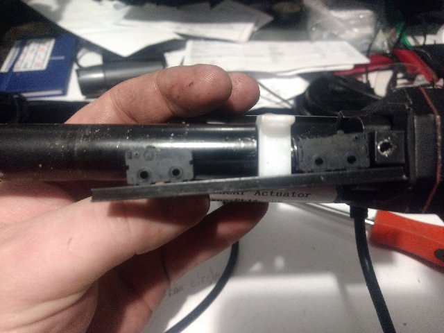
I use the full extension of the linear motor but did not need the full retraction. I moved the retract limit switch to the position on the rail which gave me a stop point where the headlight is fully lowered.
This did require de-soldering the limit switch and moving it. Make sure you keep the diode in the right direction when resoldering the connections. I hope your soldering skills are better than mine. Be very careful at this stage. If the wire contacts the case, the motor may still work until you get it in the car. Then strange things start to happen. (don't ask me how I know)
[This message has been edited by JMTUT (edited 03-26-2019).]
I had read on the forums many reasons why a linear motor would not work on the fiero headlights and being the contrary person I am, I decided to give it a try.
This is kind of a basic question, but is the linear motor you're using designed to work in a wet environment?
As you can tell. The motor is about 1.5 seconds slower than the left original. There are faster motors out there or I can change the gearing in this one and lose a little power. I wanted to prove out the concept before I go to the expense of running another motor.
I have ordered a motor from ebay that looks like it will be a lot faster for the other side.
Nice write up but Sorry, your Limit Switches setup likely have problems now and soon.
Now... Look like Won't stop when jammed at any travel point. Gen 1 limit switch and Gen 2 modules does just that. Yes, Gen 1 switches can turn on when any jam is removed and Gen 2 just kill power until you try open/close again but both try to protect the system.
Soon... Motors Assembly maybe "Wash down" tolerate but the Switches are likely Not even rated for that and water/dirt will attack them. If they fail Open then is a big pain in the ass. If they fail Closed then motors can break whatever and draw Full Stall Amps and burn out the weakest wiring. If they fail partially Close then motors will see the power drop and draw more Amps as in my Cave, Electric Motors, where many fried the motors, relays etc. Standard Fuses/Links often won't protect these problems.
IOW Motors w/ problem switches at EoT or Jammed anywhere can break the motors, whatever attach to and/or melt or cause fires like both factory setups have done. Is why Gen 1 have a Thermal Breaker in the motors. Cliff P and a few others "Repair" Gen 2 modules only to melt the module and 1 or both motors at minimum.
Plus small "Cherry Style" you have and other small switches won't last long w/ "big" DC loads. "Big" often is > 1 to 2 DC Amps. Most Amp Ratings on the case are only AC. Run DC and derate that to Half or Less or expect contacts to burn fast. Even much heavier PW switch like Fiero uses burns out contacts and worse if windows have binding problems. Is not just Inductive loads either. Many have tried DIY HL Main and/or Dimmer switches only to have small switches melt and is a purely Resistance Loading that's can be well under AC Amp Rating on the case.
Related Example: Old/Cheap Garage Door motors often only have EoT switches and break things when chain/belt/screw jams. Some have Shear "Pins" but system is still broken until "pin" are replace. (Could be Pin, Bolts, or just "Weak" gears that break.) Or Could be anything else like Kids Pets etc in Path of Travel. Kids have been hurt or kill from Door Openers and why Most Building Codes now Requires them to have Light stop, Bump stop, etc, so can't close w/ anything block the door. Newer/Better systems have Better Limit switch setups or Amp Draw monitoring of some type to stop breaking parts when jammed like Fiero like Gen1 and Gen2 setup but All require to have extra protection like breaking the Light Beam shutting down the system.
------------------ Dr. Ian Malcolm: Yeah, but your scientists were so preoccupied with whether or not they could, they didn't stop to think if they should. (Jurassic Park)
Thank you for the input Ogre. The knowledge you have on this car continues to amaze me. I do think there is a danger of the mechanical system binding and breaking so I built the weak point as the rod I installed. It will bend/break before the arms on the mechanical assembly. I know because I broke one during bench testing. The limit switches on these are installed inside the casing so they are indeed protected from water spray. All connections I made used adhesive sealed heat shrink tubing. I have ithought about installing a motor controller which will monitor current spike but for this use, it may be unnecessary. The existing fiero relays are all in place so any danger of overload is no higher than the original design.
I do think this is a viable alternative to the original motors and allows us to use many different brands of actuators easily available on the market. The actuators range from low cost units to some that are rated for underwater use.
Just a thought here kind of spitballing..... On the Bremen Sebring kit cars the headlights housings were welded to a common tube shaft running across from each headlight. A small linear actuator was mounted underneath the center of the tube and was connected by a single steel arm. A dash mounted power window momentary rocker switch put it up and down...... It was a pretty simple and neat design. When I sold my last Sebring the original 36 year old linear actuator was working just like when new. I had 4 Sebrings over the years and none of them ever had a failure in that system.
Ok, so I've not read well but I'm assuming none of the fancy wiring or modules would be needed, this could be run off standard relays on the actual headlight circuit?
Ignore the Orge, he means well I'm sure but he's got to find reasons to object to everything.
I did not have to run any extra wiring. The fiero already is set up to reverse polarity. Just wire the down blue wire and the grey wire (on the passenger) side together and the green to the up wire on the linear motor. I'm still considering mounting the light to the door itself and just lifting the whole thing. That would eliminate the extra space and mechanical complexity. The motor wouldn't even have to be attached to the light door. Just push it up.
There is room in the front of the fiero to attach a torque tube to run both lights but I worry about redundancy. As designed you usually at least get one light if something fails. I suppose you could put a pin in it so it could be raised manually. Regardless, this does show a linear motor can perform the function and be quicker than original design.
That's actually a great idea....the arm attaching to the tube could have that extra pin link hole for simple manual up/down if you had linear actuator failure.
The linear activator is really a great idea that you have come up with. This might be the ideal replacement solution for the troublesome 84-86 headlight motors. As for the concern with jamming , causing damage or a fire, you can just fuse the power line. If it somehow jams, the current in the supply line rises and the fuse blows; no harm done.
------------------ " THE BLACK PARALYZER" -87GT 3800SC Series III engine, custom ZZP /Frozen Boost Intercooler setup, 3.4" Pulley, Northstar TB, LS1 MAF, 3" Spintech/Hedman Exhaust, P-log Manifold, Autolite 104's, MSD wires, Custom CAI, 4T65eHD w. custom axles, Champion Radiator, S10 Brake Booster, HP Tuners VCM Suite. "THE COLUSSUS" 87GT - ALL OUT 3.4L Turbocharged engine, Garrett Hybrid Turbo, MSD ign., modified TH125H " ON THE LOOSE WITHOUT THE JUICE "
In order to increase reliability / decrease wear, maybe slower is better. I wouldn't be too concerned at the speed they currently move.
I like the slower speed of the actuator powered headlights. The OEM setup comes up fast sometimes with a clunking sound. The actuator system appears to operate much smoother. The only drawback might be that it still uses the complex Fiero system of relays and modules. IMO a problem point for reliability.
------------------ " THE BLACK PARALYZER" -87GT 3800SC Series III engine, custom ZZP /Frozen Boost Intercooler setup, 3.4" Pulley, Northstar TB, LS1 MAF, 3" Spintech/Hedman Exhaust, P-log Manifold, Autolite 104's, MSD wires, Custom CAI, 4T65eHD w. custom axles, Champion Radiator, S10 Brake Booster, HP Tuners VCM Suite. "THE COLUSSUS" 87GT - ALL OUT 3.4L Turbocharged engine, Garrett Hybrid Turbo, MSD ign., modified TH125H " ON THE LOOSE WITHOUT THE JUICE "
DL your video and sad news... Gen2 w/ New Cardone Motors are way faster that that. Count the frames... Video is 30fps(Exact 29.896fps)... Yours is ~ 51 frames, ~ 1 and 2/3 seconds, to have both doors open.
Is under FMVSS and most states rules that allow 3 seconds But...
From my Dash Cam data posted last year, Gen2 is 20 frames, 2/3 of 1 sec, to open. Is so fast that measuring motor volts/amps is very hard because most digital meter don't update the screen fast enough. Even most analog meters won't read fast enough. Need a meter w/ hold or chart functions or storage Oscope. OEM Gen2 motors was also under 1 sec to open, OEM Gen1 was a little slower then Gen2 but don't have video to count frames for them.
Someone else can upload to YT. I not creating YT media for this.
Originally posted by Fiero2m4Fastback: Ok, so I've not read well but I'm assuming none of the fancy wiring or modules would be needed, this could be run off standard relays on the actual headlight circuit?
Ignore the Orge, he means well I'm sure but he's got to find reasons to object to everything.
Is very oblivious you don't understand. Many others don't either. You find out why Gen1 limit switches And the motor parts that run them actually work only when you jam the lift assembly or doors partway open/close as ice and other road crap can do. The Gen1 Relays Do Not care about stopping the motors for jammed parts or at End of Travel. Gen2 system goes farther and shut off power to a jammed motor at any point trying to open or close.
Garage door is important because Gen1 system is very related to many Garage Door Openers sold for 50+ years. Many GDO units have motors mounted in rubber or other things that allowing the case to rotate/move as load requires but the case will hit limit switch(es) when loads are too high like the door crushing a kid. Better ones often use similar method as Gen2 with monitoring amp draw by the motor. In GDO case this is Not Good Enough and even with bump stop and light break stops GDO still hurts or kills people every year. You not hear them in News feeds because this is too common to cover beyond maybe local TV/radio.
Gen1 Limit switches are only 1/2 of stopping the motor. Other half is the "pin" and motor shaft itself. To run the motor, it runs w/ only minor loads on the shaft and pin stays close centered axially. Jammed or EoT then the shaft climbs up/down the driven gear making the pin to force one switch off.
Above system Does Not seem to have this and only Stops at EoT. It likely doesn't have the "Backup" breaker to shut off when the normal switches fail to open as Gen1 has. Blowing 20a Taillight fuse isn't same thing as tripping a breaker/fuse in/on the motor. Many crap parts sold on Ebay and other Chinese outlets like Banggood have problems like that. Trying to "fix" them to work for a given app often have problems that can fry the wiring or cause a fire.
[This message has been edited by theogre (edited 04-10-2019).]
Originally posted by 2.5: In order to increase reliability / decrease wear, maybe slower is better. I wouldn't be too concerned at the speed they currently move.
Who are you Kidding? Fiero doors and lifts happily handle both OE systems when installed right and minor maintain the parts over 30+ years. That's ignoring bad grounds etc that need work too after Decades of use.
Clean all door/lift parts, lube metal parts w/ Dry Teflon (Teflon is safe but Binders/Carriers in most Dry lubes often hate plastic until they dry.), reassemble and done w/ most maintenance. Big Problem is many remove/replace the lift or doors and never bother that lift has slotted holes when they mount to the tire wall for a reason. Now most are mounted low and often to one side and rub the hood. Others are missing trim screws allowing trim side(s) to bind on the hood.
Most Hidden HL problems are simple abuse by owners and kids. Kids will play and run HHL to death if they can. Even Gen2 is not made to handle open/close/repeat for long. Sometime ice etc can jam the system but when the system works the motors will stop and in Gen2 will shut off and stay off until you operate HL switch again but many idiot just keep trying to open/close the HHL w/o look at why they shut off. I've seen old Vacuum operated HHL w/ broken parts for same reasons.
[This message has been edited by theogre (edited 04-10-2019).]
I don't know what all the complaints are about this guys headlight actuator system but it works. Again if anyone is worried about jamming, a fuse can be added for safety. The rise in current can blow the fuse and will just shut the actuator off. The key is to figure out the stall current at the jam point and fuse accordingly. I see no real problems with this guys actuator system
------------------ " THE BLACK PARALYZER" -87GT 3800SC Series III engine, custom ZZP /Frozen Boost Intercooler setup, 3.4" Pulley, Northstar TB, LS1 MAF, 3" Spintech/Hedman Exhaust, P-log Manifold, Autolite 104's, MSD wires, Custom CAI, 4T65eHD w. custom axles, Champion Radiator, S10 Brake Booster, HP Tuners VCM Suite. "THE COLUSSUS" 87GT - ALL OUT 3.4L Turbocharged engine, Garrett Hybrid Turbo, MSD ign., modified TH125H " ON THE LOOSE WITHOUT THE JUICE "
I don't know what all the complaints are about this guys headlight actuator system but it works. Again if anyone is worried about jamming, a fuse can be added for safety. The rise in current can blow the fuse and will just shut the actuator off. The key is to figure out the stall current at the jam point and fuse accordingly. I see no real problems with this guys actuator system
Well said, Dennis.
Great job on this project JMTUT!!!
------------------ "Discord" Red 1988 GT under restoration!
I actually appreciate all the input on these actuators. The 35 year old motors in the system obviously worked very well over the years and one only recently failed. The linear actuator I am using is simply showing an alternative method to the current system design. In my opinion, the weak point is using the existing relays which are just as old. I have no experience with Gen 1 headlights that work well or Gen 2 lights at all. The only timing I have is the existing system on my car and the linear motor system is faster. I don't like the design of the original system as it uses unnecessarily complicated mechanical linkage and makes a lot of noise. I believe this can be improved upon by using modern, less expensive electronics, and by working out the factors which led to battery drain problems, etc on the original system. I will keep improving the design until I have something easy to install and may then offer the plans to other people in the fiero community.
Please continue to critique any design problems so I can keep them in mind as I move forward with this.
John
[This message has been edited by JMTUT (edited 04-16-2019).]
Glade to see others using them too. With the actuators being the most expensive component of the system; I’m going to try one unit to drive a central shaft for both sides, and also plan to use a clutch disk to prevent damage should a door be frozen shut by ice, etc.
Originally posted by Francis T: Glade to see others using them too. With the actuators being the most expensive component of the system; I’m going to try one unit to drive a central shaft for both sides, and also plan to use a clutch disk to prevent damage should a door be frozen shut by ice, etc.
Many things uses a mechanical clutches but often have problems. Example farm equipment uses them like often on/in PTO input to a mower etc. Adjusting them so they work and protect is harder then most think w/o a clutch pack made for a specific application. Just a bit loose and behaves w/ false jams and is Very annoying at minimum. If you run whatever for long w/ a loose clutch then the clutch won't last long or burn out and even cause a fire. Just a bit tight and often fry/break whatever that's weaker. Basically Same as using Delrin "Pins" in Gen2 motor, just breaks the gear and/or output shaft because Delrin is way too hard.
If you use clutch(es) to limit load at End of Travel for the HL lifts as normal, the clutch is harder to make w/o problems.
These motor need limit switches used like Gen1 system or electronics (and programming) emulate Gen2 Module. "Arduino" et al with the right support "chips" could make a "module" w/ the same Gen2 features. Meaning shuts off Each Motor w/ high current for jamming or at normal End of Travel and shuts off power after ~ 5 sec for other issues like some disconnects HL motors in Winter. Linear motor(s) likely need more amps to run it/them so would need to tweak the program in the "Arduino" chip or other changes to the driver circuit that just make a Gen2 board.
Do you have a good multimeter? Can you set it up to get a reading on the current draw? Put it in series with one of the power wires, probably wont matter which one since the polarity switches..
------------------ Project Genisis Lo Budget 3800SC swap 12.840@104.8 MPH Intense-Racing 1.9 rockers, 3" exhaust, 3.4 pulley, ZZP tune and 18 year old tires.
Originally posted by JMTUT: Unfortunately, I only have the cheap Harbor freight meter so I can't measure current draw.
Don't bother... If your new motor setup is fast... Likely will have same problem trying to read Amps on Gen1 or Gen2 setups. I have several meters of different types are all have problems reading fast events.
A. You have 3 numbers that matter... 1. Starting current, AKA Inrush Current, when a motor etc starts up. 2. Running current. When you see Amps Spec on a motor etc, this is where number comes from. 3. Stall current when motors Jams or at End of Travel. 1 & 3 can be 2 to many times the Running Current. Example: Engine Starter rated at 1.5kw eats ~ 120a at 12.6v running... But inrush current when you first turn the key is easily 2x to 4x of that number.
B. Most meter displays are not quick enough to read. Gen2 motors run ~ ⅔ of One Sec. Gen1 working right are slower but not enough for most meters. Most Analog meters have meter protection so needle can't slam and can't read fast events. A-meters w/o this can't read them either because needle overshoots the real value for fast events. Most Digital Meters of any kind only update their screens 1 or 2 times per sec. Max hold function either reads starting or stall current and you have no clue which value it reads as max. IOW most meters can't tell amp draw to tell you much here or program an "arduino board." Would need a scope meter or storage O-scope w/ current shunt to capture load curve for opening and closing a door.
C. If you try to emulate Gen2 board... You likely deal w/ all three current values. Board need to pass 1 and 2 and kill power for 3. Problem is 1 can be = or higher then 3 so is likely not a simple as just turning on power to the motor and monitor amp load. Simple timer doesn't help when a motor is stalled for any reason. The Whole motor may not get hot in 1 to 5 sec but Brushes and other parts can and even burn out in short order. Gen2 "Backup" timer is to kill power if motors have no load because of broken lift parts etc or module is "bad" and can't read motor amps to prevent motor melting @ EoT or jamming.
There is one more piece of the puzzle to consider.. when the motor turns off, there is usually a back EMF pulse. Since the switch opened, the current is converted into a high voltage, arcing across the contacts and making short work of them. The key is to use diodes in the right orientations so that when the motor turns off, the current flows through the diodes. Just google back emf protection.
Originally posted by Chris Eddy: There is one more piece of the puzzle to consider.. when the motor turns off, there is usually a back EMF pulse. Since the switch opened, the current is converted into a high voltage, arcing across the contacts and making short work of them. The key is to use diodes in the right orientations so that when the motor turns off, the current flows through the diodes. Just google back emf protection.
Simple Diodes won't work for motor that spin both ways. Same issue for PW motors that have nothing to stop motor back EMF that eats up many PW Switches. (Not only a Fiero problem.)
Gen2 Module have 330Ω 1/8w or 1/4w resistors to do this and does work for decades. (R14 and R15 in https://www.fiero.nl/forum/F.../HTML/140432.html#p9 ) Can run very small watt resistors because motor on "shorts them out" then turn off the motors the resistor see Milliseconds to Microseconds of Back EMF that can't heat them to burn out. Can run MOV and others to maybe to do it better and doesn't care about polarity.
ETA--> I'm skipping many points to emulate Gen2 w/ Arduino of any kind like most will eat a lot more power vs. real Gen2 board w/o making them sleep when not needed. W/o proper sleep design (is often is a function of hardware and software design.) Arduino and support chips can drain the battery fast enough to not start the car after only a week or three. Like a switch to dome/trunk light is stuck on.
[This message has been edited by theogre (edited 09-26-2019).]
Originally posted by JMTUT: The linear motors have diodes installed in line with the limit switches.
Depending just how they are wired... These Diodes likely do little for back EMF wiring in series w/ any switches.
Diodes for back EMF are wiring in parallel w/ a coil w/ Plus side of diode to Plus power. (Gen2 R14 and R15 resistors are wired same but in the module not in the motor itself.)
One direction Motors work same but when motor/coil is reverse powered the diode most likely will die but coil still works. In fact many replace TC Clutch solenoid wrong way around, blow the diode in it then have problems w/ switches and even the ECM w/o back EMF protection. Many have dead AC clutch diode have same problems and why DormanWells(@RA) etc have AC diodes as PnP or pigtails parts. (One Wells' pic barely shows the diode under the heat shrink.)
Other devices may look like simple diodes but are wired same for surge and back EMF protection. Some of these devices may like reveres DC and AC power. I don't think Bipolar/Bi-directional TVS "Diodes" were available in 80's. Even if was available, the GM bean counters could fight them costing even a fraction of a cent more then the resistors used on Gen2 board.
{QUOTE}Simple Diodes won't work for motor that spin both ways. Same issue for PW motors that have nothing to stop motor back EMF that eats up many PW Switches. (Not only a Fiero problem.)
Gen2 Module have 330Ω 1/8w or 1/4w resistors to do this and does work for decades. (R14 and R15 in https://www.fiero.nl/forum/F.../HTML/140432.html#p9 ) Can run very small watt resistors because motor on "shorts them out" then turn off the motors the resistor see Milliseconds to Microseconds of Back EMF that can't heat them to burn out. Can run MOV and others to maybe to do it better and doesn't care about polarity.
ETA--> I'm skipping many points to emulate Gen2 w/ Arduino of any kind like most will eat a lot more power vs. real Gen2 board w/o making them sleep when not needed. W/o proper sleep design (is often is a function of hardware and software design.) Arduino and support chips can drain the battery fast enough to not start the car after only a week or three. Like a switch to dome/trunk light is stuck on.
[/QUOTE]
Using 4 diodes, you can arrange a back EMF protection. Google full bridge with back EMF. The 330 ohm resistor is not really for soaking up back EMF.. a resistor and cap in series can be a "snubber" to do that though. They probably found that it kept the voltage spike down to an acceptable level though, and saved $$ leaving the caps out. And you could put Transient Suppression Diodes (back to back) across the motor to do that too.
This thread needs to be revisited but specifically for a replacement for the GEN 1 motors. If your Gen1 motor breaks replacements are unavailable and if the motor is not rebuildable then there are no alternatives. I'd like to start using a Linear actuator on my 85GT. The mounting seems straight forward but the electrical circuit will need some work.
------------------ " THE BLACK PARALYZER" -87GT 3800SC Series III engine, custom ZZP /Frozen Boost Intercooler setup, 3.4" Pulley, Northstar TB, LS1 MAF, 3" Spintech/Hedman Exhaust, P-log Manifold, Autolite 104's, MSD wires, Custom CAI, 4T65eHD w. custom axles, Champion Radiator, S10 Brake Booster, HP Tuners VCM Suite. "THE COLUSSUS" 87GT - ALL OUT 3.4L Turbocharged engine, Garrett Hybrid Turbo, MSD ign., modified TH125H " ON THE LOOSE WITHOUT THE JUICE "
This thread needs to be revisited but specifically for a replacement for the GEN 1 motors. If your Gen1 motor breaks replacements are unavailable and if the motor is not rebuildable then there are no alternatives. I'd like to start using a Linear actuator on my 85GT. The mounting seems straight forward but the electrical circuit will need some work.
Actually the Gen 1 circuit already reverses the polarity. All we need to do here is to fuse the supply leads and do the mechanical mount. Should be easy.
------------------ " THE BLACK PARALYZER" -87GT 3800SC Series III engine, custom ZZP /Frozen Boost Intercooler setup, 3.4" Pulley, Northstar TB, LS1 MAF, 3" Spintech/Hedman Exhaust, P-log Manifold, Autolite 104's, MSD wires, Custom CAI, 4T65eHD w. custom axles, Champion Radiator, S10 Brake Booster, HP Tuners VCM Suite. "THE COLUSSUS" 87GT - ALL OUT 3.4L Turbocharged engine, Garrett Hybrid Turbo, MSD ign., modified TH125H " ON THE LOOSE WITHOUT THE JUICE "