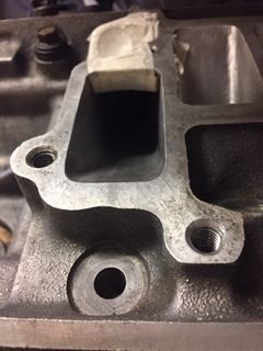
Finally this is the result on the exhaust port. I tried to get these delta-graphs as true as possible. The exact same setup and the same port position.
Difference between stock and ported exhaust
Almost to good to be true and the top end would be further improved if positioned on the cylinder. My DIY test bench may be slightly imprecise but it is pretty obvious that the flow can be dramatically improved by some porting on these heads.
Originally posted by lordfiero: It is going to be a 3.4 with stock look, but with more flow and higher revving
Are you going to use an F-body block or 3400? I recommend a 3400 block. You end up spending a few more dollars on valve train stuff to make it work but going roller cam is pretty sweet and you don't have to drill starter holes since they are already there. I want to do a 3.7" bore for 3.5L in my next build...
[This message has been edited by lou_dias (edited 04-17-2019).]
An LX9 is just an overbored LA1. In fact, rebuilding an LX9 would be even more trouble since that's even more of an overbore over a stock LA1. Better to just bore an LA1 to 94mm and then use stock LFX pistons for some good CR.
I wouldn't be suprised if the LFX crank with it's slightly longer stroke (3.37" vs 3.31") could be used on an LA1 block... Perhaps that is part of La Fiera's plan for a 3.7L engine...
That and LA1's are dime-a-dozen motors in yards usually with blown head or intake gaskets...
[This message has been edited by lou_dias (edited 04-17-2019).]
The LX9 block casting is different to accept the larger bore from the factory. I don't know if the coolant passages line up with the iron heads or not, though.
The High Feature engines are a clean sheet design. There is no reason to expect that anything as complex as a crankshaft is interchangeable. After all, the only parts that interchange from a traditional Chevy to an LS are the rod bearings and valve lifters.
Hmmm... the timing gear and chain are narrower which of course reduces rotating mass... Another nice low-tech performance bump... Using larger cam journals also makes it easier to turn the cam if the cam gear is also larger. Little things like this add up to the extra power produced by this motor over the expected increase from the .1 L displacement increase.
Hmmm... the timing gear and chain are narrower which of course reduces rotating mass... Another nice low-tech performance bump... Using larger cam journals also makes it easier to turn the cam if the cam gear is also larger. Little things like this add up to the extra power produced by this motor over the expected increase from the .1 L displacement increase.
Looks like a couple of the coolant holes don't line up. One would have to cast a very very critical eye to water jacket compatibility if trying that...
...but again - I would never consider those blocks as a donor... LA1's are a dime-a-dozen...
If I could pick a *new* V6 today to put in a new Fiero stock, it would be the LFX... It's in my Colorado and it makes plenty of power. My only complaint is the sledomatic it's attached to...
[This message has been edited by lou_dias (edited 04-18-2019).]
Easy choice for me, I already have a healthy L32 block waiting for action Otherwise 3900 would be interesting if there was available cam blanks for that one.
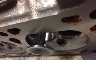
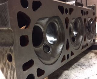
Heads back from machine shop They got recut valves and seats, I also shaved 0.6mm from the surface to get compression right. The exhaust unshrouding and combustion chamber smoothing set head combustion chamber to 52cc, now its approx 3.5cc lower.
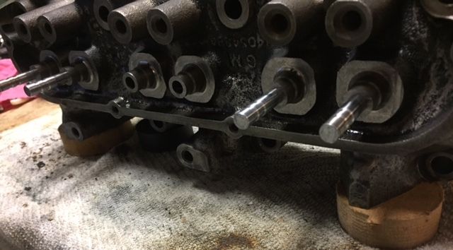
Most performance valve springs need more height than available in this head/valve combo, so this has to be fixed.
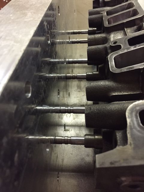
I checked the valve length with a flat surface, all valves sits pretty much at the same height.
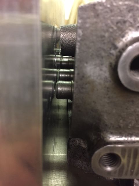
The valve guides are not level in height, look at the gap. The reason I checked this is with a high lift cam and stock valves combined with viton seals the lower groove in the valve stem will go inte the seal.
According to my service manual the valve spring installed height shall be 1.58". I checked this, and in my heads the intake and exhaust valves are different in spring height, I do not know if this is poor tolerances or intentional but im going for 1.7" at both intake and exhaust.
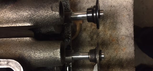
The top of the valve guide has now been shortened , but I still have 2" valve guide length. The spring seats have been machined down to equal height between valves.
After this mod I can run up to 0.5" lift on both valves without interference with the valve seal and the new seat position allows 1.7" springs to be used.
The intake and exhaust valves have the lock grooves in sligthly different position, this can be adjusted with thin spacers under the spring or even more simple, changing the lock plate.
Heads back from machine shop They got recut valves and seats, I also shaved 0.6mm from the surface to get compression right. The exhaust unshrouding and combustion chamber smoothing set head combustion chamber to 52cc, now its approx 3.5cc lower.
Did you give them specs for the valve job? That can have a significant effect on low lift flow.
The top of the valve guide has now been shortened , but I still have 2" valve guide length. The spring seats have been machined down to equal height between valves.
After this mod I can run up to 0.5" lift on both valves without interference with the valve seal and the new seat position allows 1.7" springs to be used.
The intake and exhaust valves have the lock grooves in sligthly different position, this can be adjusted with thin spacers under the spring or even more simple, changing the lock plate.
All heads I've done are machined to use Chevy 350 springs, the choices of springs are endless.
Good job!!
Edit for spelling
[This message has been edited by La fiera (edited 04-30-2019).]
Started to measure the lower intake manifold. I dont want to handle the finished heads so Im using one of my test intake head ports for this. The flow is slightly less than the finished heads but not that far away.
This is the setup, the intake valve is put upside down to block the valve stem hole and provide max head flow.
I found that the area around the edges of the lower intake manifold intakes are not as sensitive to edge interference as the cylinder head intake ports so I measured this without any round edges (on bare cylinder heads it is critical to use round edges, often formed by clay).
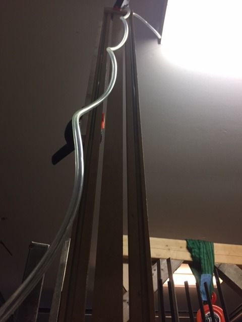
btw someone asked about the flow bench, this is the U-tube pressure meter. Note the side mounted scale and the high tech device of moving/holding it..
I did notice a restriction of >10CFM when LIM is used on these ported heads. I would not worry about the LIM on stock heads.
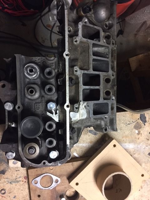
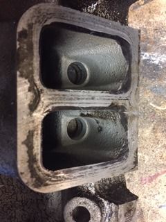
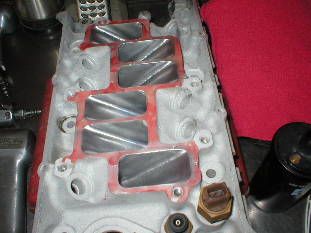
I noticed that the LIM port outlet is blocked in two corners, marked with black. The third port that is offset from the two others is only blocked in one corner, but that lump is twice the size.
Removing this and shape a smooth transition of the walls from the injector position to the port did help the flow.
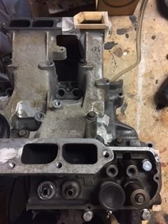
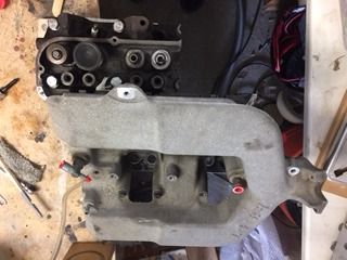
Middle Intake Manifold, MIM.. This was a big surprise.. I read many concerns about the goose neck on the upper intake manifold, but why worry about that when the MIM runners cant supply the heads with sufficient air anyhow. Flow is down 20% with the setups below.
Separate MIM prepped for optimum measurements
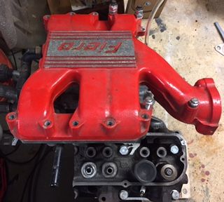
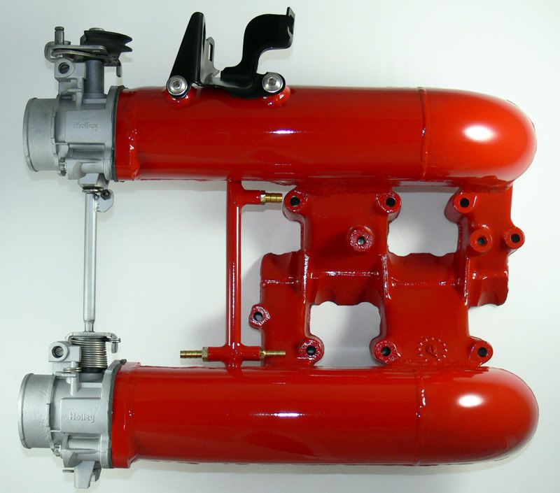
Together with Fiero UIM
Together with Camaro UIM
The flow performance was so bad I had to measure the LIM again but with the same reults I dont think the MIM can be fixed by porting out the stock shapes any longer. This is a problem..
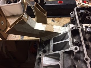
I cut the top .3" off the MIM. This opens the port(s) to the inside perhaps 1/8" and allows for better porting and polishing of that cross section. You'll need to cut the gaskets to take advantage of this.
Yes cutting down the runner is an option or even slicing it to sections before porting, thanks for the input. Unfortunately I need to get the flow up a lot..
At the moment Im working on the optional way of doing it, adding material
I would like to add width but that is not possible when the runners are packed so xxxx close to each other.
Looking at my inner walls, you can see my ports are opened up more than your picture above. The LIM shouldn't be a restriction when you're done. Remember, all these pieces were originally cast with 2.8L in mind...
Middle Intake Manifold, MIM.. This was a big surprise.. I read many concerns about the goose neck on the upper intake manifold, but why worry about that when the MIM runners cant supply the heads with sufficient air anyhow. Flow is down 20% with the setups below.
Separate MIM prepped for optimum measurements
Together with Fiero UIM
Together with Camaro UIM
The flow performance was so bad I had to measure the LIM again but with the same reults I dont think the MIM can be fixed by porting out the stock shapes any longer. This is a problem..
That's why "dual plenum" or "dual throttle" manifolds which are made by cutting off the top 1-2 inches of the MIM perform so much better than stock with few other mods.
What I couldn't convey then that I can now is about using water to flow bench. Water has a lot more mass than air and doesn't like to change direction. Air simply follows to the lower pressure area regardless of which direction that is in. Doesn't care so much about direction change and that's why your can increase flow with polishing more than a mild port with a rough polish. So flow benching is a good guide to finding restrictions in the grand scheme of things but air will still outperform the expectations of a flow bench in many cases.
This goes back to the philosophical differences me and Rei and the OP have about the intake vane. I believe it's there to balance pressure around the valve as do a lot of engine builders but a flow bench will tell you that you increase flow by removing it. So I digress...
[This message has been edited by lou_dias (edited 06-12-2019).]
I've ported 3.4L P/R engine heads and there is a difference in performance but its not dramatic. I had to get around the remaining restrictions by adding a turbocharger with boost. IMO there is only so much that you can do to get these 60* V6 engines to breath really well. GM even went so far as to add new heads w quad valves in a DOHV configuration and got 215 HP. This is a decent step up for this engine but not near what other swapped engines can provide. Point is to not expect miracles when porting the V6 P/R engine heads.
------------------ " THE BLACK PARALYZER" -87GT 3800SC Series III engine, custom ZZP /Frozen Boost Intercooler setup, 3.4" Pulley, Northstar TB, LS1 MAF, 3" Spintech/Hedman Exhaust, P-log Manifold, Autolite 104's, MSD wires, Custom CAI, 4T65eHD w. custom axles, Champion Radiator, S10 Brake Booster, HP Tuners VCM Suite. "THE COLUSSUS" 87GT - ALL OUT 3.4L Turbocharged engine, Garrett Hybrid Turbo, MSD ign., modified TH125H " ON THE LOOSE WITHOUT THE JUICE "
Originally posted by lou_dias: This goes back to the philosophical differences me and Rei and the OP have about the intake vane. I believe it's there to balance pressure around the valve as do a lot of engine builders but a flow bench will tell you that you increase flow by removing it. So I digress...
Lou, the vane is there to promote air velocity which translate into torque but at high rpm it becomes a restriction. For a street driven car the vanes gives instant response, and great low end torque but at high RPM when air volume is needed, that's where the vane lacks. I know your engine and mine are totally diffent but look at the torque you are producing at about 3200rpm, its about 210ft/lbs and mine is making 230ft/lbs of torque. Not much difference! But look what happens at 4500rpms, you make about 196-197ft/lbs of torque and I make 300ft/lbs, there is a 103ft/lbs of torque difference at that RPM and the higher in the RPM band they go your power suffers more becase it can't only flow enough due to the vane restriction. If I were to put your heads on my engine I probably would've picked up 25-30ft/lbs more between 2000 and 3000rpms but after that I would probably loose them as fast past those RPMS. Plug one of your nostrals and run a sprint as fast as you can and measure how far and how fast you covered that distance. Then do the same test with both nostrals, that will give you an idea of the theory.
The main problem with the LIM and MIM is not the area, it is the air stream direction. The LIM turns/rotates the air upwards and the MIM is an almost straight pipe. I can reduce the area and gain lots of flow at all pressures IF everything above the LIM (including fuel rail) are wasted in the garbage bin. I would like to keep a stock look so Im trying to find a way to make it work.
Most of those modified intakes have the same problem. I only seen one I believe in so far..
What I couldn't convey then that I can now is about using water to flow bench. Water has a lot more mass than air and doesn't like to change direction. Air simply follows to the lower pressure area regardless of which direction that is in. Doesn't care so much about direction change and that's why your can increase flow with polishing more than a mild port with a rough polish. So flow benching is a good guide to finding restrictions in the grand scheme of things but air will still outperform the expectations of a flow bench in many cases.
This goes back to the philosophical differences me and Rei and the OP have about the intake vane. I believe it's there to balance pressure around the valve as do a lot of engine builders but a flow bench will tell you that you increase flow by removing it. So I digress...
I've heard of people using glycol (antifreeze) mist and UV light to visualize the flow paths.
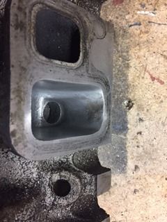
Blocking the upper outer part of the LIM proved to boost the flow through all my different MIM test runners. I think the stock shape gained the most. When measuring the LIM alone this may seem as a reduction in flow but this to direct the air from the MIM to the LIM, so the gain is only seen when both parts are connected.
Middle Intake Manifold, MIM.. This was a big surprise.. I read many concerns about the goose neck on the upper intake manifold, but why worry about that when the MIM runners cant supply the heads with sufficient air anyhow. Flow is down 20% with the setups below.
Separate MIM prepped for optimum measurements
Together with Fiero UIM
Together with Camaro UIM
The flow performance was so bad I had to measure the LIM again but with the same reults I dont think the MIM can be fixed by porting out the stock shapes any longer. This is a problem..
I'm sure there may be some happy medium there where perhaps I could have drilled equal sized smooth holes in the walls and polished them and deburred/smoothed everything out and perhaps not lost as much mid-range and kept most of the top end gains but desperate times called for desperate measures.


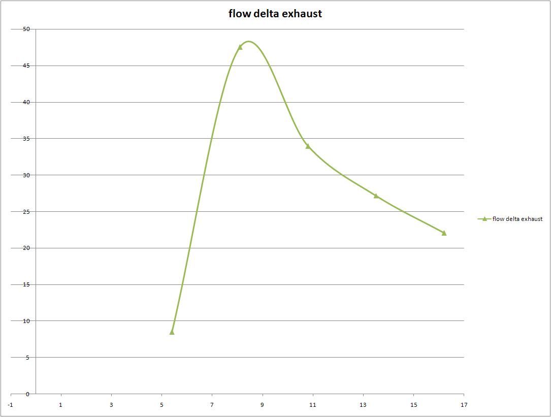
 and the top end would be further improved if positioned on the cylinder. My DIY test bench may be slightly imprecise but it is pretty obvious that the flow can be dramatically improved by some porting on these heads.