Pennock's Fiero Forum
  Technical Discussion & Questions
  HVAC control swap

Post New Topic  Post A Reply
Email This Page to Someone! | Printable Version


next newest topic | next oldest topic
HVAC control swap by sactodreamer
Started on: 04-18-2014 04:18 PM
Replies: 7 (1005 views)
Last post by: jscott1 on 04-26-2014 02:57 AM
sactodreamer
Member
Posts: 169
From: Sacramento, CA
Registered: Nov 2003


Feedback score: N/A
Leave feedback

Rate this member

Report this Post04-18-2014 04:18 PM Click Here to See the Profile for sactodreamerSend a Private Message to sactodreamerEdit/Delete MessageReply w/QuoteDirect Link to This Post
I'm working on changing over the Fiero HVAC controls and using 91-95 Camry controls for my replica build. I found the following info in this archived thread: Anyone ever modify heater controls to round knob style?

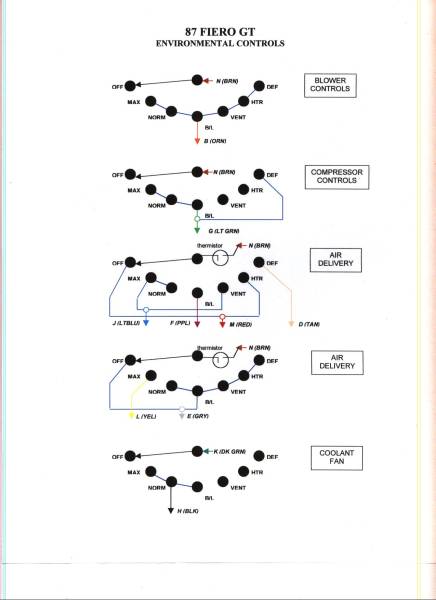
The connector to the climate control PC board has thirteen connections:

A - Illumination lamp supply
B - Fan power (hot if OFF not pressed)
C - Illumination lamp ground
D - Hot to get DEFROST outlet
E - Hot to get FRESH inlet
F - Hot to get BILEV outlet
G - A/C on signal to ECM
H - GND for engine cooling fan relay
J - Hot to get VENT outlet
K - Engine cooling fan relay enable
L - Hot for RECIRC inlet
M - Hot for FLOOR outlet
N - 12V power to the control unit
(hot in run)


I've gotten just about all of it mapped for the Camry system but I need to know what letters H and K do. The way I interpret it is H provides a ground to the coolant fan relay and K provides +12v. I'm guessing that is to kick on the fan when the A/C is turned on.

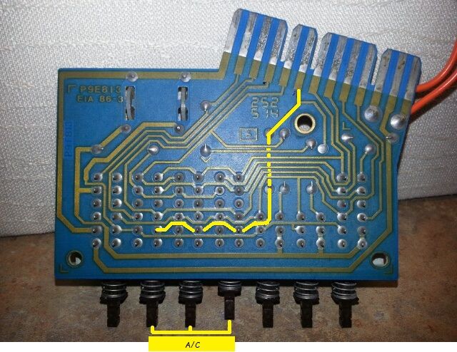
Here is the "H" circuit.


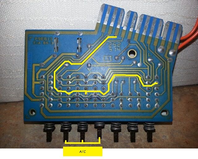
Here is the "K" circuit.

[This message has been edited by sactodreamer (edited 04-18-2014).]

IP: Logged
PFF
System Bot
phonedawgz
Member
Posts: 17091
From: Green Bay, WI USA
Registered: Dec 2009


Feedback score:    (23)
Leave feedback


Total ratings: 290
Rate this member

Report this Post04-18-2014 08:26 PM Click Here to See the Profile for phonedawgzClick Here to visit phonedawgz's HomePageSend a Private Message to phonedawgzEdit/Delete MessageReply w/QuoteDirect Link to This Post
Here is the "H" circuit.


Here is the "K" circuit.


IP: Logged
jscott1
Member
Posts: 21676
From: Houston, TX , USA
Registered: Dec 2001


Feedback score:    (15)
Leave feedback


Total ratings: 415
Rate this member

Report this Post04-18-2014 09:56 PM Click Here to See the Profile for jscott1Send a Private Message to jscott1Edit/Delete MessageReply w/QuoteDirect Link to This Post
It's very simple when H and K are connected the radiator fan will come on. I used a separate switch such that I can turn the fan on whenever I want.

Most people that do the Firebird dash convert to rotary controls.

IP: Logged
sactodreamer
Member
Posts: 169
From: Sacramento, CA
Registered: Nov 2003


Feedback score: N/A
Leave feedback

Rate this member

Report this Post04-20-2014 01:28 AM Click Here to See the Profile for sactodreamerSend a Private Message to sactodreamerEdit/Delete MessageReply w/QuoteDirect Link to This Post
Thanks for the info! Thanks phonedawgz for fixing my pictures.

[This message has been edited by sactodreamer (edited 04-20-2014).]

IP: Logged
seajai
Member
Posts: 1541
From: Linwood Township, Minnesota
Registered: Feb 2012


Feedback score:    (42)
Leave feedback


Total ratings: 52
Rate this member

Report this Post04-20-2014 08:46 AM Click Here to See the Profile for seajaiSend a Private Message to seajaiEdit/Delete MessageReply w/QuoteDirect Link to This Post
 
quote
Originally posted by sactodreamer:

I'm working on changing over the Fiero HVAC controls and using 91-95 Camry controls for my replica build..........I've gotten just about all of it mapped for the Camry system but I need to know what letters H and K do. The way I interpret it is H provides a ground to the coolant fan relay and K provides +12v. I'm guessing that is to kick on the fan when the A/C is turned on.


I am currently finishing up a 1992 Camry dash swap in my 88gt and I have questions. Are you using the HVAC controls with the rotary mode selector or push buttons? I picked up a push button one yesterday and found a wiring diagram manual here: http://www.turboninjas.com/camry/ . The problem I see is that both the blower switch and mode selector switch operate on the ground side of the circuit, whereas the Fiero HVAC operated on the power side of the circuit. It looks like the rotary mode selector could be adapted but the push button one could not because of the LED's in the buttons. The other issue is the blower switch. The blower motor receives a constant voltage through the heater relay and the ground side runs through the resistor block. Also, high speed is run through the switch instead of a relay like on the Fiero. The way the Fiero blower circuit is wired, there really isn't a good way to make the Toyota switch work. I was thinking about adapting this switch to work.

Just wondering what your plan was to adapt things, thanks.

IP: Logged
FTF Engineering
Member
Posts: 710
From: Near Philadelphia PA
Registered: Sep 2001


Feedback score: (1)
Leave feedback

Rate this member

Report this Post04-21-2014 09:22 PM Click Here to See the Profile for FTF EngineeringSend a Private Message to FTF EngineeringEdit/Delete MessageReply w/QuoteDirect Link to This Post
jscott1 nailed the function, but just in case you're interested in how...

The coolant fan relay has one side of it's coil connected to battery any time the key is in the ON position. In order to get that relay to close (and turn on the cooling fan) you have to ground the other side of that relay coil and that's done by the HVAC module.

H is a ground connection and K is connected to the low side of the fan relay. When you connect K to ground (H) you enable the relay and the fan turns on.
IP: Logged
seajai
Member
Posts: 1541
From: Linwood Township, Minnesota
Registered: Feb 2012


Feedback score:    (42)
Leave feedback


Total ratings: 52
Rate this member

Report this Post04-25-2014 09:12 AM Click Here to See the Profile for seajaiSend a Private Message to seajaiEdit/Delete MessageReply w/QuoteDirect Link to This Post
How's your project coming along? I got my control head up and running last night, I posted my solution in my build thread if you're interested in looking. //www.fiero.nl/forum/F...L/000139-7.html#p270
IP: Logged
jscott1
Member
Posts: 21676
From: Houston, TX , USA
Registered: Dec 2001


Feedback score:    (15)
Leave feedback


Total ratings: 415
Rate this member

Report this Post04-26-2014 02:57 AM Click Here to See the Profile for jscott1Send a Private Message to jscott1Edit/Delete MessageReply w/QuoteDirect Link to This Post
 
quote
Originally posted by seajai:

How's your project coming along? I got my control head up and running last night, I posted my solution in my build thread if you're interested in looking. //www.fiero.nl/forum/F...L/000139-7.html#p270


That is some beautiful work on your dash swap. Love the hvac. I just solderwd all my relays together no custom circuit board. I just realized the other day I probably destroyed a billion brain cells with all the lead solder vapor I've breathed over the years.
IP: Logged

next newest topic | next oldest topic

All times are ET (US)

Post New Topic  Post A Reply
Hop to:

Contact Us | Back To Main Page

Advertizing on PFF | Fiero Parts Vendors
PFF Merchandise | Fiero Gallery | Ogre's Cave
Real-Time Chat | Fiero Related Auctions on eBay


Copyright (c) 1999, C. Pennock