Pennock's Fiero Forum
  Technical Discussion & Questions
  Redesign a Fiero suspension for better geometry (Solidworks, ProEngineer, etc) (Page 9)

Post New Topic  Post A Reply
Email This Page to Someone! | Printable Version

This topic is 10 pages long:  1   2   3   4   5   6   7   8   9   10 
Previous Page | Next Page
next newest topic | next oldest topic
Redesign a Fiero suspension for better geometry (Solidworks, ProEngineer, etc) by Austrian Import
Started on: 06-30-2011 06:13 PM
Replies: 395 (47878 views)
Last post by: 84fiero123 on 02-28-2016 10:30 AM
Datsun1973
Member
Posts: 120
From: Fort Worth, TX
Registered: Mar 2006


Feedback score: N/A
Leave feedback

Rate this member

Report this Post03-02-2012 07:15 PM Click Here to See the Profile for Datsun1973Send a Private Message to Datsun1973Edit/Delete MessageReply w/QuoteDirect Link to This Post
I'll try to get some pictures up but I have converted my 88' rear suspension to a full SLA. The car is still in my trailer after the move so it may be a bit.

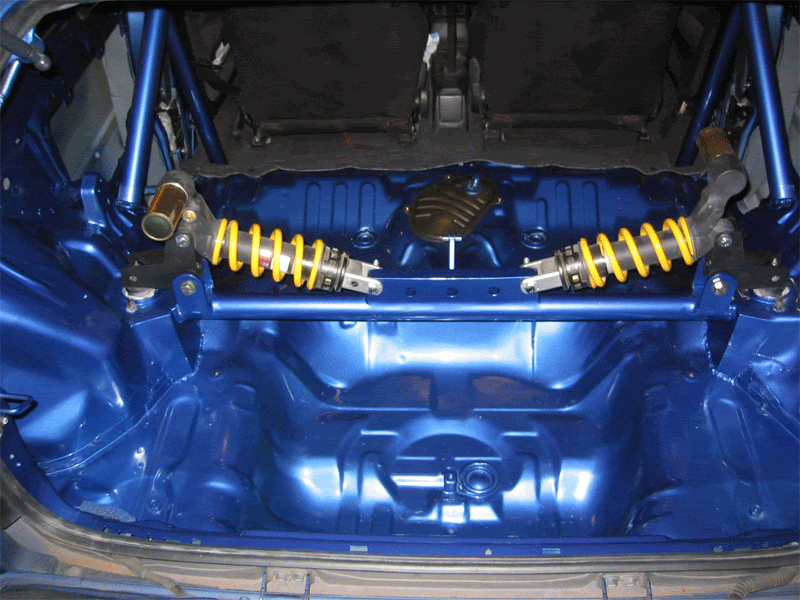
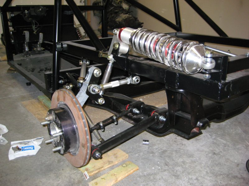
The two lower transverse links are stock. I used urethane bushings in them. The lower pivot point was machined to accept a 5/8" hiem. The cradle point, same. The lower long lateral link is now a basic sprint car threaded tube with a heim on either end. The upper mount is a little bit more complex. I made two plates that sandwich where the strut would attach. Those plates look something like an "L." This is where the push rod attaches to actuate the coil-over. Some will ask why this point and the key is load path. By attaching the spring/shock to the upper part of the hub carrier you run the load through the path the OEM engineers intended. Attaching to the lower link is not a good idea because you induce bending loads where they were never meant to be (although I think the lower link is beefy enough to handle it). The upper arm is again made of 5/8" heim joints for the transverse link that runs from the lower of the two holes and to the upper frame rail. A second upper lateral link runs forward from the front side of the carrier to the upper frame rail. In the end you essentially have a SLA that is infinately adjustable with good camber gain. The roll center and momment also appear to be fairly good as well.

The coil-overs are mounted on the upper frame rail horizontally orientated front to back. They are actuated through a machined rocker that rides on ball bearings.

This type of setup may or may not work in a stock fiero. My car has a tube frame that uses Fiero underpinnings.

IP: Logged
Bloozberry
Member
Posts: 7760
From:
Registered: Jan 2009


Feedback score: N/A
Leave feedback


Total ratings: 311
Rate this member

Report this Post03-02-2012 08:51 PM Click Here to See the Profile for BloozberrySend a Private Message to BloozberryEdit/Delete MessageReply w/QuoteDirect Link to This Post
Where have you been all this time! If you have the three dimensional spacial coordinates of the upper control arm pivots (referenced to some other known stock point) as well as those for the shock, the kinematics can be mapped out to show the advantages. I've posted the stock coordinates elsewhere so only the changes would be needed. Pics would be great, but data is even better.
IP: Logged
ricreatr
Member
Posts: 586
From: Flint, mi
Registered: May 2004


Feedback score: N/A
Leave feedback

Rate this member

Report this Post03-02-2012 09:14 PM Click Here to See the Profile for ricreatrSend a Private Message to ricreatrEdit/Delete MessageReply w/QuoteDirect Link to This Post
ALLRIGHTY THEN!!!!!!

this is gonna be good. i can wait for THOSE pictures!!
are you the one they made the rule exception for???
(maybe a hand drawing to tide us over in the mean time)

side note: the last sketch i did of the simple upper arm has poor choice of heim in the knuckle. accel/decel forces would work to push the ball out of its socket, so it will not work as is. would need a ball joint of some sort installed with a bracket.

IP: Logged
Austrian Import
Member
Posts: 3919
From: Monterey, CA
Registered: Feb 2007


Feedback score: N/A
Leave feedback

Rate this member

Report this Post03-07-2012 04:17 PM Click Here to See the Profile for Austrian ImportSend a Private Message to Austrian ImportEdit/Delete MessageReply w/QuoteDirect Link to This Post
can't wait.
IP: Logged
Datsun1973
Member
Posts: 120
From: Fort Worth, TX
Registered: Mar 2006


Feedback score: N/A
Leave feedback

Rate this member

Report this Post03-07-2012 04:31 PM Click Here to See the Profile for Datsun1973Send a Private Message to Datsun1973Edit/Delete MessageReply w/QuoteDirect Link to This Post


Yes that is an LZ4 running with the OEM computer and harness. VVT and all is functioning. VATS, rear O2 and other sensors were deleted with HP Tuners.

[This message has been edited by Datsun1973 (edited 03-07-2012).]

IP: Logged
Jefrysuko
Member
Posts: 3491
From: Oreana IL
Registered: Apr 2000


Feedback score:    (17)
Leave feedback


Total ratings: 108
Rate this member

Report this Post03-07-2012 07:05 PM Click Here to See the Profile for JefrysukoSend a Private Message to JefrysukoEdit/Delete MessageReply w/QuoteDirect Link to This Post
 
quote
Pictures posted by Datsun1973:


That's really cool. Do you have a sway bar hidden in there somewhere?
IP: Logged
Datsun1973
Member
Posts: 120
From: Fort Worth, TX
Registered: Mar 2006


Feedback score: N/A
Leave feedback

Rate this member

Report this Post03-07-2012 07:35 PM Click Here to See the Profile for Datsun1973Send a Private Message to Datsun1973Edit/Delete MessageReply w/QuoteDirect Link to This Post
Thanks. No sway bar yet but there is room to add one later if needed. I subscribe to the Carol Smith design school (Tune to Win, Engineer to Win, etc) books. Sway bars are band aids for bad designs. I am sure folks on here will dispute me on that but Carol is the man.
IP: Logged
ricreatr
Member
Posts: 586
From: Flint, mi
Registered: May 2004


Feedback score: N/A
Leave feedback

Rate this member

Report this Post03-08-2012 12:11 AM Click Here to See the Profile for ricreatrSend a Private Message to ricreatrEdit/Delete MessageReply w/QuoteDirect Link to This Post
THAT IS ABSOLUTELY AWESOME!!

thanks for posting pics soon.

do you have about 4" total travel?
these seem to be pics from a while ago, so it might not be possible, but can you get a pic of the shock absorber rocker from a straight on angle? (have been playing around with pushrod sketches, and dont really know what i am doing)
have you had it on the road/track yet?

thanks again!
IP: Logged
Datsun1973
Member
Posts: 120
From: Fort Worth, TX
Registered: Mar 2006


Feedback score: N/A
Leave feedback

Rate this member

Report this Post03-08-2012 05:03 PM Click Here to See the Profile for Datsun1973Send a Private Message to Datsun1973Edit/Delete MessageReply w/QuoteDirect Link to This Post
Travel is around 4" I think. This car was designed as a road course machine with limited emphisis on travel and more on roll control and maximum tire contact patch.

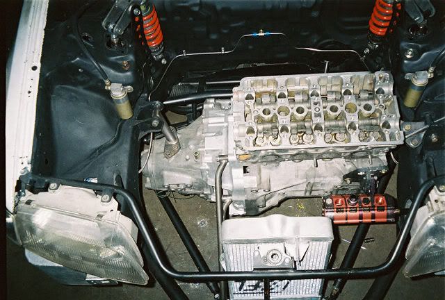
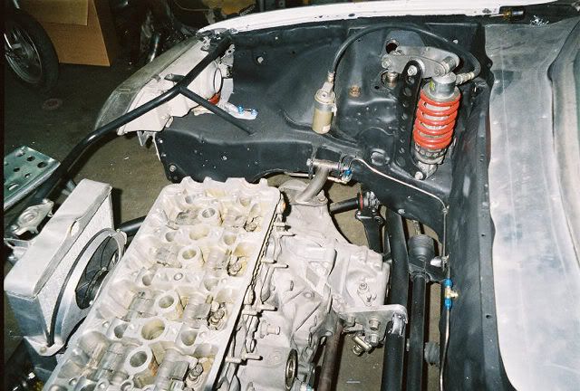
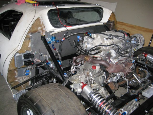
Actually the picture with the engine is from last summer when I was doing the initial engine wiring and first start. The basic frame is about 2 years ago.

The car is in storage so actual pictures will be difficult right now. As for rocker arms I didn't change the motion ratio and just used a simple 1:1 ratio. The easiest way to design a rocker is pick your shock location and rocker point. Using a circle with the rocker pivot as the center of that circle you can pick two points for the ends of the rocker. I would recomend the Carol Smith books, Tune to Win and Engineer to Win. He outlines some basics for suspension design and goes over things like mountings in double shear, load paths, what metals to use, etc etc. Great read. Unless you NEED an inboard or remote mounted shock/spring there is no performance benefit to this setup for a common road car. I did it because I couldn't figure out a way to mount a QA1 large body shock and spring outboard with the corvette wheels and 305 series tires. In board shocks/springs also reduce unsprung weight and allow a greater number of motion ratios, again not a player for a common road car. You also need to consider cost. Those rockers were CNC machined out of billet 7075 and the heim's are top quality chrome-moly units from AED motorsports.

A better alternative for a stockish fiero is Fieroguru's post on relocating the strut inboard. Hopefully he will make a kit similar to his link relocation kit.

The car does drive, but has only been into and out of the trailer. I am working on the shift cables to the F23 right now. The shift cable doesn't have enough throw so I need to trim down the jacket material and see if I can get an additional 1/2" of throw.
IP: Logged
Bloozberry
Member
Posts: 7760
From:
Registered: Jan 2009


Feedback score: N/A
Leave feedback


Total ratings: 311
Rate this member

Report this Post03-08-2012 06:37 PM Click Here to See the Profile for BloozberrySend a Private Message to BloozberryEdit/Delete MessageReply w/QuoteDirect Link to This Post
Very clean looking design. Do you have any data or graphs showing the kinematic performance of camber, toe, and roll center in bump and roll?
IP: Logged
fieroguru
Member
Posts: 12128
From: Champaign, IL
Registered: Aug 2003


Feedback score:    (45)
Leave feedback


Total ratings: 258
Rate this member

Report this Post03-08-2012 07:29 PM Click Here to See the Profile for fieroguruSend a Private Message to fieroguruEdit/Delete MessageReply w/QuoteDirect Link to This Post
 
quote
Originally posted by Datsun1973:


That is pretty cool!
IP: Logged
PFF
System Bot
Datsun1973
Member
Posts: 120
From: Fort Worth, TX
Registered: Mar 2006


Feedback score: N/A
Leave feedback

Rate this member

Report this Post03-08-2012 07:31 PM Click Here to See the Profile for Datsun1973Send a Private Message to Datsun1973Edit/Delete MessageReply w/QuoteDirect Link to This Post
Yes and No. I did the design using scale "paper dolls" and push pins to check the dynamics. When I did the Formula SAE cars in college I had several software packages that accomplished the same thing. I will try to get measurements once the car gets home and you can map it out. I am curious to see how close I got. However, with any suspension design it's always a compromise between roll center, roll momment, anti-squat, and packaging. I would have preferred the lower and upper arms to be longer but with the transverse mounted engine/trans this is very difficult to package.

I thought you'd get a kick out of this too:


[This message has been edited by Datsun1973 (edited 03-08-2012).]

IP: Logged
Datsun1973
Member
Posts: 120
From: Fort Worth, TX
Registered: Mar 2006


Feedback score: N/A
Leave feedback

Rate this member

Report this Post03-08-2012 07:35 PM Click Here to See the Profile for Datsun1973Send a Private Message to Datsun1973Edit/Delete MessageReply w/QuoteDirect Link to This Post

Datsun1973

120 posts
Member since Mar 2006
Thanks guru!
IP: Logged
Austrian Import
Member
Posts: 3919
From: Monterey, CA
Registered: Feb 2007


Feedback score: N/A
Leave feedback

Rate this member

Report this Post03-13-2012 04:07 PM Click Here to See the Profile for Austrian ImportSend a Private Message to Austrian ImportEdit/Delete MessageReply w/QuoteDirect Link to This Post
 
quote
Originally posted by Datsun1973:

Thanks. No sway bar yet but there is room to add one later if needed. I subscribe to the Carol Smith design school (Tune to Win, Engineer to Win, etc) books. Sway bars are band aids for bad designs. I am sure folks on here will dispute me on that but Carol is the man.


Sway bars are band aids. Have you seen the suspension setup on the McLaren MP4-12c? They completely did away with sway bars and replaced it with hydraulics.
IP: Logged
Austrian Import
Member
Posts: 3919
From: Monterey, CA
Registered: Feb 2007


Feedback score: N/A
Leave feedback

Rate this member

Report this Post03-13-2012 04:17 PM Click Here to See the Profile for Austrian ImportSend a Private Message to Austrian ImportEdit/Delete MessageReply w/QuoteDirect Link to This Post

Austrian Import

3919 posts
Member since Feb 2007
 
quote
Originally posted by Datsun1973:


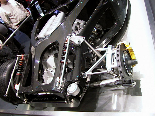
That setup is even better looking that what I envisioned when I started this thread. Please post more pictures and info. If something like this could be adapted to the Fiero, that would be awesome.

A pushrod suspension like this on the front would look gorgeous as well.

Unsprung weight matters on street cars as well. (just not as dramatic). Going from 14" rims+tires at 35lbs total to 18" rims+tires at 49lbs total, I could totally tell the handling difference, turn in response, etc. Adapted from Colin Chapman I believe, "weight does not like to change direction".

IP: Logged
Austrian Import
Member
Posts: 3919
From: Monterey, CA
Registered: Feb 2007


Feedback score: N/A
Leave feedback

Rate this member

Report this Post03-16-2012 01:31 AM Click Here to See the Profile for Austrian ImportSend a Private Message to Austrian ImportEdit/Delete MessageReply w/QuoteDirect Link to This Post
Datsun1973, is there a build thread on any forum about this car?
IP: Logged
Austrian Import
Member
Posts: 3919
From: Monterey, CA
Registered: Feb 2007


Feedback score: N/A
Leave feedback

Rate this member

Report this Post03-16-2012 01:57 AM Click Here to See the Profile for Austrian ImportSend a Private Message to Austrian ImportEdit/Delete MessageReply w/QuoteDirect Link to This Post

Austrian Import

3919 posts
Member since Feb 2007
*double post*

[This message has been edited by Austrian Import (edited 03-16-2012).]

IP: Logged
Austrian Import
Member
Posts: 3919
From: Monterey, CA
Registered: Feb 2007


Feedback score: N/A
Leave feedback

Rate this member

Report this Post03-16-2012 02:21 AM Click Here to See the Profile for Austrian ImportSend a Private Message to Austrian ImportEdit/Delete MessageReply w/QuoteDirect Link to This Post

Austrian Import

3919 posts
Member since Feb 2007
This is another approach:


http://www.rx7club.com/show...9401318&postcount=11


or a setup like this with a longitudinal Subaru/Porsche boxer engine.
IP: Logged
Austrian Import
Member
Posts: 3919
From: Monterey, CA
Registered: Feb 2007


Feedback score: N/A
Leave feedback

Rate this member

Report this Post07-06-2012 02:35 AM Click Here to See the Profile for Austrian ImportSend a Private Message to Austrian ImportEdit/Delete MessageReply w/QuoteDirect Link to This Post
bump for updates
IP: Logged
el_roy1985
Member
Posts: 295
From: Bismarck, ND, USA
Registered: Jun 2004


Feedback score: N/A
Leave feedback

Rate this member

Report this Post08-28-2012 09:20 PM Click Here to See the Profile for el_roy1985Send a Private Message to el_roy1985Edit/Delete MessageReply w/QuoteDirect Link to This Post
Sick suspension setup. After looking at Lambos and such, this is the approach I had planned to take in the future. Nice to see someone actually did it, and it also gives me a lot of insight on how to go about mine in the future.
IP: Logged
Austrian Import
Member
Posts: 3919
From: Monterey, CA
Registered: Feb 2007


Feedback score: N/A
Leave feedback

Rate this member

Report this Post10-24-2012 07:27 PM Click Here to See the Profile for Austrian ImportSend a Private Message to Austrian ImportEdit/Delete MessageReply w/QuoteDirect Link to This Post
http://www.martinwhite.name.../88cradle/index.html using this to bump the thread.

Can't wait to see more designs with double wishbone, or multi-link rears.
IP: Logged
PFF
System Bot
Ang84Indy
Member
Posts: 576
From: Ohio
Registered: Jul 2009


Feedback score:    (7)
Leave feedback

Rate this member

Report this Post10-25-2012 10:02 PM Click Here to See the Profile for Ang84IndySend a Private Message to Ang84IndyEdit/Delete MessageReply w/QuoteDirect Link to This Post
This is a very informative thread! Thanks to all who have contributed. I have a question: A while back there was a discussion about staggered tire/wheel widths. When going to a larger width rear wheel, is there a formula to figure proper size, or does one just guess?
IP: Logged
fieroguru
Member
Posts: 12128
From: Champaign, IL
Registered: Aug 2003


Feedback score:    (45)
Leave feedback


Total ratings: 258
Rate this member

Report this Post10-26-2012 06:20 AM Click Here to See the Profile for fieroguruSend a Private Message to fieroguruEdit/Delete MessageReply w/QuoteDirect Link to This Post
 
quote
Originally posted by Ang84Indy:

This is a very informative thread! Thanks to all who have contributed. I have a question: A while back there was a discussion about staggered tire/wheel widths. When going to a larger width rear wheel, is there a formula to figure proper size, or does one just guess?


Section width variation front/rear should be close to the weight bias front/rear.
So if your car is 46%(F) / 54%(rear) you could run 205's in front and 240's in the rear or 215/250 or 225/265 or 235/275

IP: Logged
Boostdreamer
Member
Posts: 7175
From: Kingsport, Tennessee USA
Registered: Jun 2007


Feedback score:    (24)
Leave feedback


Total ratings: 98
Rate this member

Report this Post10-26-2012 09:52 AM Click Here to See the Profile for BoostdreamerSend a Private Message to BoostdreamerEdit/Delete MessageReply w/QuoteDirect Link to This Post
@Datsun1973, what is the spring rate on your rear coilovers? I would expect that they would need to be really soft in that configuration.

Jonathan
IP: Logged
Ang84Indy
Member
Posts: 576
From: Ohio
Registered: Jul 2009


Feedback score:    (7)
Leave feedback

Rate this member

Report this Post10-26-2012 12:22 PM Click Here to See the Profile for Ang84IndySend a Private Message to Ang84IndyEdit/Delete MessageReply w/QuoteDirect Link to This Post
Thanks Fieroguru!
IP: Logged
daveheld
Member
Posts: 95
From: Cocoa Beach FL
Registered: Nov 2010


Feedback score: (4)
Leave feedback

Rate this member

Report this Post11-12-2012 07:44 PM Click Here to See the Profile for daveheldClick Here to visit daveheld's HomePageSend a Private Message to daveheldEdit/Delete MessageReply w/QuoteDirect Link to This Post
here's another option... and it's for sale.

dave
Cocoa Beach FL


IP: Logged
IVANNATINKLE
Member
Posts: 913
From: Kansas United states
Registered: Jun 2009


Feedback score: (1)
Leave feedback

Rate this member

Report this Post11-12-2012 11:46 PM Click Here to See the Profile for IVANNATINKLESend a Private Message to IVANNATINKLEEdit/Delete MessageReply w/QuoteDirect Link to This Post
how does it attatch to the fiero?
IP: Logged
IVANNATINKLE
Member
Posts: 913
From: Kansas United states
Registered: Jun 2009


Feedback score: (1)
Leave feedback

Rate this member

Report this Post11-19-2012 12:28 AM Click Here to See the Profile for IVANNATINKLESend a Private Message to IVANNATINKLEEdit/Delete MessageReply w/QuoteDirect Link to This Post
What about something like this http://www.xj40.com/viewtop...c030dcd3eaa&start=30 ?
IP: Logged
aaron88
Member
Posts: 280
From: Ottawa, Canada
Registered: Oct 2003


Feedback score: (2)
Leave feedback

Rate this member

Report this Post11-24-2012 12:25 PM Click Here to See the Profile for aaron88Send a Private Message to aaron88Edit/Delete MessageReply w/QuoteDirect Link to This Post
Does anyone know of a rear knuckle similar to the Fiero 88 one?

As it turns out it was a lot easier to figure out how to correct the rear geometry than it is turning out to be to figure out how to do it cheaper than a complete custom job (about $4500). I have my cradle built and the lower control arms designed but my hang up is figuring out how to make it connect with the 84-87 rear knuckle without making a custom knuckle. Every solution I come up with drives the cost up. All the solutions that I have come up with are not rigid enough, or have transitions with high stress concentration points.

So I'm wondering if there is something out there that can be slightly modified to work. But by my lack of ability to locate one by now makes me assume that there is none. I will probably have to design and make custom rear knuckles (which would solve the bearing, caliper, strut mount and ball joint problems), but obviously drive the price up.

My lower control arm design is still as posted previous (and below).


Cradle design below.


.
IP: Logged
Austrian Import
Member
Posts: 3919
From: Monterey, CA
Registered: Feb 2007


Feedback score: N/A
Leave feedback

Rate this member

Report this Post01-23-2013 01:40 PM Click Here to See the Profile for Austrian ImportSend a Private Message to Austrian ImportEdit/Delete MessageReply w/QuoteDirect Link to This Post
bump in hopes of new contribution
IP: Logged
Will
Member
Posts: 14226
From: Where you least expect me
Registered: Jun 2000


Feedback score: (1)
Leave feedback


Total ratings: 237
Rate this member

Report this Post01-23-2013 02:24 PM Click Here to See the Profile for WillSend a Private Message to WillEdit/Delete MessageReply w/QuoteDirect Link to This Post
 
quote
Originally posted by daveheld:

here's another option... and it's for sale.

dave
Cocoa Beach FL


Why is the cradle attached so close to the center instead of on a wider mount center? That must compromise the torsional stiffness of the interface significantly.
IP: Logged
PFF
System Bot
aaron88
Member
Posts: 280
From: Ottawa, Canada
Registered: Oct 2003


Feedback score: (2)
Leave feedback

Rate this member

Report this Post01-23-2013 10:28 PM Click Here to See the Profile for aaron88Send a Private Message to aaron88Edit/Delete MessageReply w/QuoteDirect Link to This Post
Going to be made soon. For an 86 but using a Blazer bearing, Corvette brakes and relocated strut mount to clear wider tires.


Slow but progress is ongoing.
IP: Logged
Will
Member
Posts: 14226
From: Where you least expect me
Registered: Jun 2000


Feedback score: (1)
Leave feedback


Total ratings: 237
Rate this member

Report this Post01-24-2013 09:52 AM Click Here to See the Profile for WillSend a Private Message to WillEdit/Delete MessageReply w/QuoteDirect Link to This Post
What sort of control arm are you going to attach to it?
IP: Logged
Yarmouth Fiero
Member
Posts: 530
From: Yarmouth, Nova Scotia, Canada
Registered: May 2012


Feedback score: N/A
Leave feedback

Rate this member

Report this Post01-24-2013 09:59 AM Click Here to See the Profile for Yarmouth FieroSend a Private Message to Yarmouth FieroEdit/Delete MessageReply w/QuoteDirect Link to This Post
Great job aaron88. Are you using ProEngineer, Inventor, Rhino.......Sorry, I didn't notice if you mentioned earlier in the thread.
Will the part be billet and cnc'd or fab'd or a combination? Its a pretty complicated part.
IP: Logged
lateFormula
Member
Posts: 1048
From: Detroit Rock City
Registered: Jul 2002


Feedback score: (2)
Leave feedback

Rate this member

Report this Post01-24-2013 11:44 AM Click Here to See the Profile for lateFormulaSend a Private Message to lateFormulaEdit/Delete MessageReply w/QuoteDirect Link to This Post
Looks like SolidWorks to me...
IP: Logged
aaron88
Member
Posts: 280
From: Ottawa, Canada
Registered: Oct 2003


Feedback score: (2)
Leave feedback

Rate this member

Report this Post01-24-2013 11:36 PM Click Here to See the Profile for aaron88Send a Private Message to aaron88Edit/Delete MessageReply w/QuoteDirect Link to This Post
Yes, it's SolidWorks 2005. I can't afford to upgrade it. But at least it has FEA as well built in.

The main parts are going to be cut on a water jet then welded together. I guess it only seems complicated because I wanted a lot of functionality out of the design. There is no left or right until I machine the main part. Bearing choice is optional between Fiero, S10 Blazer or whatever else you could want. Brake mounting point is completely adjustable and ball joint mounts are part of the main body. Strut mount is adjustable for wider tires. Then I cut out some of the open areas to lower the weight. No skin off my back as there is no additional cost for any of that. Same design can be used for all years, I just have to move the strut mount over for the 88's. CNC is way too expensive for me since I don't have one.

Control arm is the same design as shown above. I'll add a shot of the assembly drawing shortly.

.
IP: Logged
Austrian Import
Member
Posts: 3919
From: Monterey, CA
Registered: Feb 2007


Feedback score: N/A
Leave feedback

Rate this member

Report this Post01-25-2013 02:51 PM Click Here to See the Profile for Austrian ImportSend a Private Message to Austrian ImportEdit/Delete MessageReply w/QuoteDirect Link to This Post
Aaron, do you want to do a double wishbone design as well, or just a strut?
IP: Logged
aaron88
Member
Posts: 280
From: Ottawa, Canada
Registered: Oct 2003


Feedback score: (2)
Leave feedback

Rate this member

Report this Post01-25-2013 05:04 PM Click Here to See the Profile for aaron88Send a Private Message to aaron88Edit/Delete MessageReply w/QuoteDirect Link to This Post
I did look at doing double wishbone and ultimately it was way too expensive. Plus I would only be able to do it in-house. The Fiero would have to be brought to me since I would have to make pockets in the frame. So if anyone want's to go that far, for the same price you could probably back half the car, assuming the engineering was already done. And if your going to back half the car you might as well whole the car (tube frame). My thoughts anyway.
IP: Logged
zkhennings
Member
Posts: 1922
From: Massachusetts, USA
Registered: Oct 2010


Feedback score: (3)
Leave feedback

Rate this member

Report this Post02-04-2013 03:08 AM Click Here to See the Profile for zkhenningsSend a Private Message to zkhenningsEdit/Delete MessageReply w/QuoteDirect Link to This Post
I think I have an actually good idea regarding improving the geometry of the pre 88 rear suspension. I will cad something tomorrow, I don't have cad on my laptop right now as I reinstalled windows, but I will try and explain my idea. Essentially have rectangular tubing in an L shape, and it bolts where the factory control arms bolt into the cradle, and it can either be welded in at that point to the cradle or have extra bolts attaching it from the top and bottom of the cradle. Every L shaped piece of rectangular tubing would fit nicely in the opening on the cradle, and all 4 would be the same size. Then there would be holes in the now raised portion or the L that would allow the control arms to be relocated higher up which would help if the car was lowered, and it helps camber gain. The stock control arms would probably not be able to be used. The hole that the control arms would mount to could also be slotted vertically to play with different angles of control arm at ride height, and testing could be done while measuring tire temperature to see where the optimal geometry was. I am willing to try this out on my car, so I understand the forces on the L shaped pieces will cause it to torque under braking or acceleration, not really worried about cornering forces. How thick do you think the steel should be? Construction for each L would be a 4 piece deal with two flat L shaped pieces water jetted, and then two rectangular pieces that would be bent at 90 or however many degrees is appropriate because it does not need to be a right angle L. Then all 4 pieces would be welded together. It would be plenty strong, I think it is a pretty good idea. Now the harmonic balancer/ pulley wont get in the way of just raising the control arm mounts on the cradle.


The only real forces the control arms exert on the bolts are either a pulling or pushing force/ a torquing force too, but no forces in the up or down directions. So the L shaped steel would just have to be strong enough to not buckle under cornering loads. A car pulling a 1g turn weighing 2700 pounds (~1200Kg) would have to have a total force of around 12000N at the wheels. Even when assuming that one wheel is providing all of that force, steel has a yield strength of 248 MPa or 248000000N/m2. Shear stress of quarter inch steel 2 inches in length parallel to shear force for cornering times two for the two pieces of metal that would be the bracket means that (2)*(.0254)*(.25)*(.0254)*(248000000)*(2) = 160,000 N is required to shear that bracket. And quarter inch steel would be overkill

[This message has been edited by zkhennings (edited 02-04-2013).]

IP: Logged
aaron88
Member
Posts: 280
From: Ottawa, Canada
Registered: Oct 2003


Feedback score: (2)
Leave feedback

Rate this member

Report this Post02-10-2013 04:09 PM Click Here to See the Profile for aaron88Send a Private Message to aaron88Edit/Delete MessageReply w/QuoteDirect Link to This Post
Assembly drawing sketch showing control arm.


.
IP: Logged
Previous Page | Next Page

This topic is 10 pages long:  1   2   3   4   5   6   7   8   9   10 
next newest topic | next oldest topic

All times are ET (US)

Post New Topic  Post A Reply
Hop to:

Contact Us | Back To Main Page

Advertizing on PFF | Fiero Parts Vendors
PFF Merchandise | Fiero Gallery | Ogre's Cave
Real-Time Chat | Fiero Related Auctions on eBay


Copyright (c) 1999, C. Pennock