I must say thats some fecking awesome exhaust routings,
quote
it would be more effective in FL than air to air and with higher boost levels be more efficient and give more of a buffer against knock.
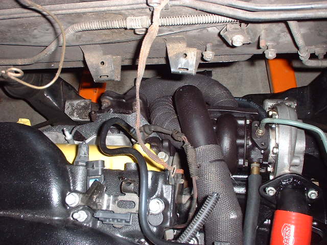
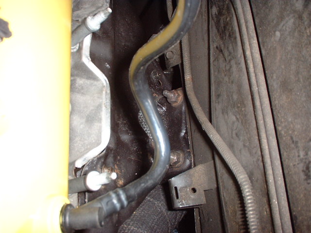
I also dont think that the air-air intercooler is going to work all that well since there wont be much air flow through the engine bay. But we shall see how well it works out, huh?
damn your only like an hour and half away from me and you do some MEAN looking welds and really good at exhaust. So could you help me with my turbo set up on my SCCA/AutoX project, Free beer lol.
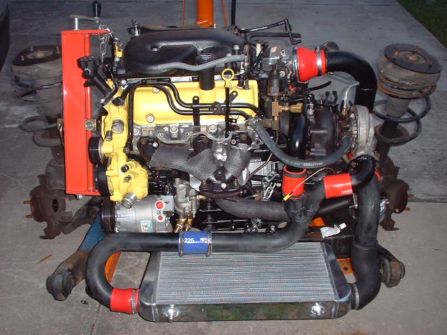
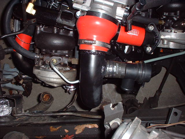
Running twin turbo's with a oil cooler is very smart and ALOT of cars that run higher boost levels have them (eclipse, RX7, Supra, 300zx, Skyline, and any car getting over 10psi) it is really smart and helps the system relieve alot of the heat from with in. Anyways it is easier to fix over cooling than over heating and I would hook up the coolers after the turbo's to bring the temps down in the engine. How are you running the mth/acl injection and what psi will it turn on at, also why not a water intercooler? it would be more effective in FL than air to air and with higher boost levels be more efficient and give more of a buffer against knock.
Thanks, as much as I like performance I'm over schedule on this project and am taking more than a month away from clinic rotations instead of the 2 wks planned to finish it thanks to the heat, but It had to be done. This is my first run in with water/meth injection and I'm trying to figure out a way to tie it in to my fuel injectors so that it pulses which would make it variable and more effective. Since the engine in stock form is rated for 87 octane with 9.8:1 compression I should be able to tune for 8 psi without the injection with 92 octane, the intercooler and programming alone plus what the oil squirters add. I say 8 psi because that's the minimum my wastegates will allow. I'll have the injection set to come on at about 8 psi and intend to run 10 psi with a gradual increase to 12.
As for water to air intercooling, it's twin turbocharged so there's a heap stuffed in the trunk already.
quote
Originally posted by AP2k:
I must say thats some fecking awesome exhaust routings,
I also dont think that the air-air intercooler is going to work all that well since there wont be much air flow through the engine bay. But we shall see how well it works out, huh?
I'll have a scoop installed to skim the air up into the intercooler core so although not as effective as a front mount cooler any reduction in inlet air temps it provides make it worth it. The flow resistance rating is pretty low.
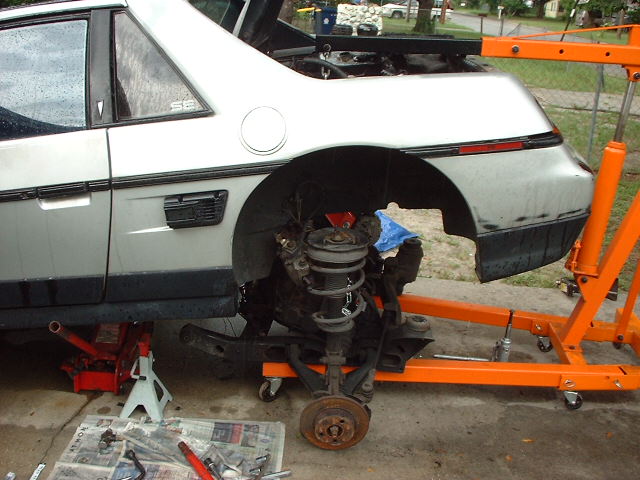
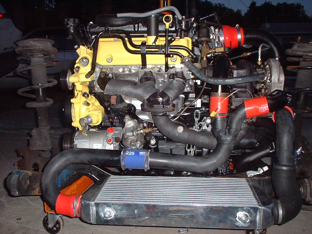
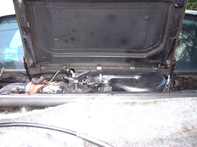
Finally it's out, the rain is impeding the process but at least the old motor is out. Hopefully I have enough welding gas left to finish up the turbo mounts, and reinforce the tranny and engine mounts. I'm down to about a quarter of a tank so I'll turn the welding gas down to about 10-12 psi and do a good tuning before welding in hopes it's enough to finish the job. If not I will not be able to refill the tank until Tuesday since the supply shops decided to make a 3 day weekend out of the up coming holiday.
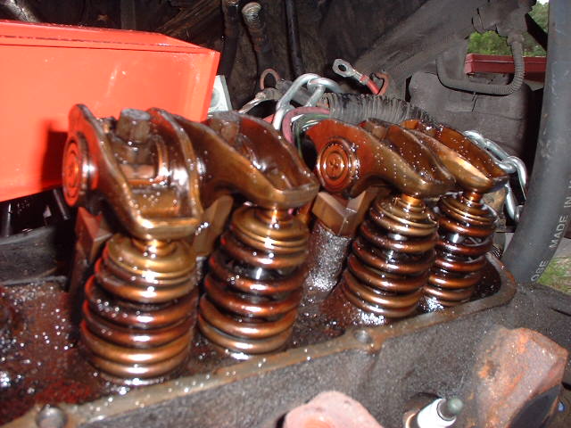
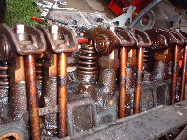
Hey! what's that? Roller fulcrum rockers with beehive springs from the front wheel drive motors on cast iron heads.
And no pushrod guide plates!
Ran the engine that way for over 5 years, hard and never had a problem. I'll have to pull the main and rod caps to see what they look like from the kind of beating they were subjected to over the years. It's a miracle I made the 460 mile trip home from Atlanta, in the process of pulling the engine I found my line to the oil sending unit was loose at the block and the cause of the oil residue I saw on the back bumper from the accelerated leak when I arrived home, and the line I thought was an A/C line that had been rubbed by my displaced muffler was actually the heater flow pipe, I barely nicked the damaged area with my pinky fingernail and it poured coolant fast enough to have put me on the side of the road in about 10 minutes or less had it leaked during the trip. A real miracle
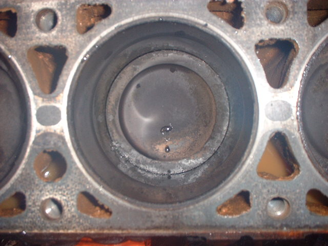
It is my understanding that a major cause of the results seen in the pictures below is higher normal operating temperatures at the rear end of the block due to preheated coolant from the front cylinders, leaner air fuel mixture due to intake design and piston location relative to inlet air and higher clearance between pistons and cylinder bore due to batch matching method.
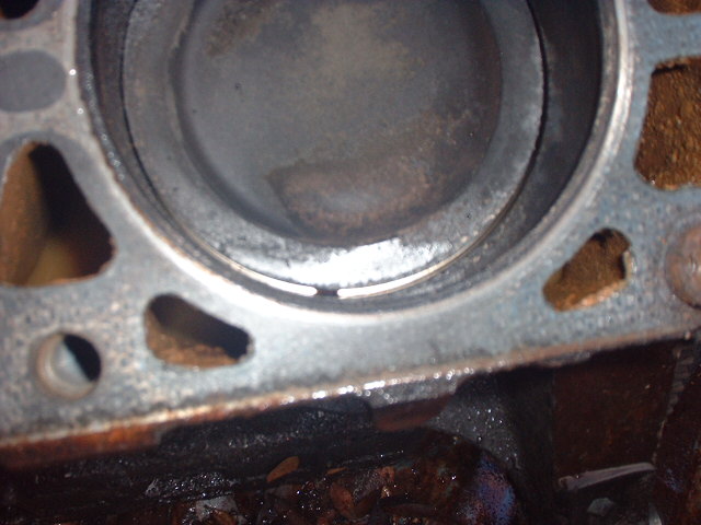
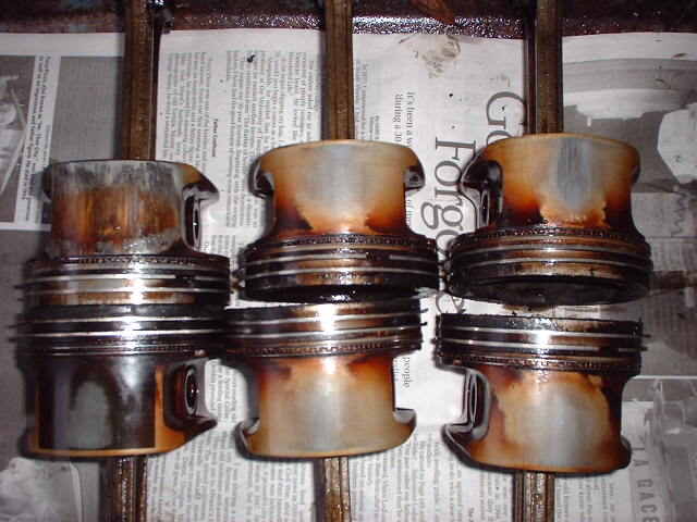
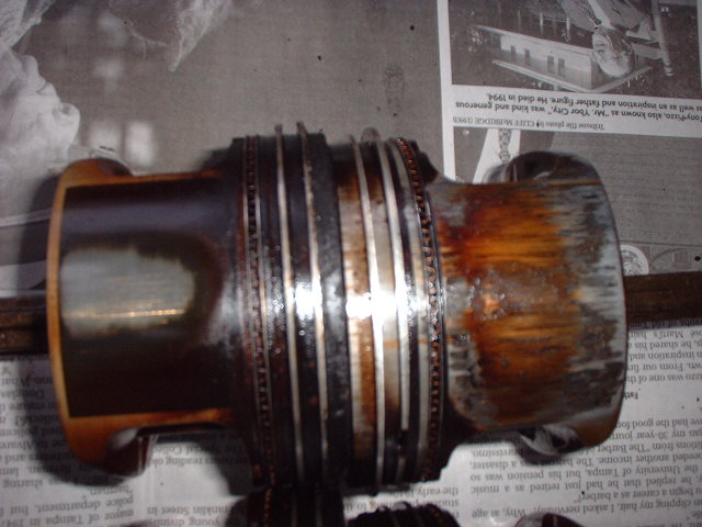
This is the 3100 short block removed from my car, it is a 2000 or later engine and was removed from a near brand new vehicle as a result of piston noise that I didn't discover until I turbocharged it and installed it in my car. I ran it hard the 5 years it was installed and resently the piston noise got louder on startup but tended to quiet down a little though always audible inside and outside of the car. As you can see it was due to melt down any minute. I was surprised to find that GM used two different pistons in the same engine, pistons 5&6 were coated with an antifriction patch though it's not visible on one side of piston 6 which is the worst. The 3500 V6 comes with oil squirters on pistons 5&6 only so I imagine the chance of it happening on that engine is much less.
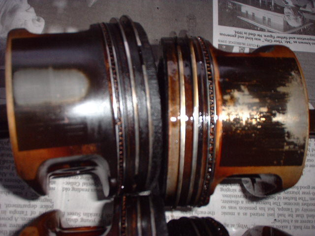
This kind of past history is good support for my intent to keep my engine temps on the low side of normal. Despite the turbo and high revs this engine hung on under the abuse. The rod bearings looked great compared to bearings I've pulled out of 2.8s that didn't see the kind of abuse this engine was subjected to, there was no copper visible or excessive wear apparent. I didn't bother to pull the main caps because the rod bearings looked so good.
Look at the clearance of piston 6 in the bore, all of the pistons had excessive clearance but this was factory related poor production given the piston racket which sounded like marbles floating around that could be heard before it ever saw boost.
Pistons are arranged according to their location in the block, note only 5 & 6 have antifriction treatment patch (6 what's left of it).
Other side of piston 6.
Gm has bumped the fuel cutoff for the 3900 up to 6400 RPM retroactively from the previous 6000 rpm, I suppose they are pretty confident about the rotating assembly strength. They are also rating the engines at a lower rpm than the previous engines giving the impression that the power has been reduced.
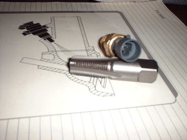
It's getting closer, there are so many little things that need to be done and that's what's slowing me down. I have the oil filter relocation mount to find a home for, I have to buy some more clamps, finish connecting the coolant hose to the turbos hook up the returnless fuel setup, connect the hydraulic line to the transmission, change the end on the A/C compressor hose so that the new style compressor can be connected to the system, install the crank sensor after I modify the spacer, the axles need to be assembled and that's all I care to think of now. I'm ready for it to be finished. Initial cranking attempt is a long shot for this weekend.
There doesn't appear to be any clearance problems, I hope not since I took measurements. This is creativity gone way to far.
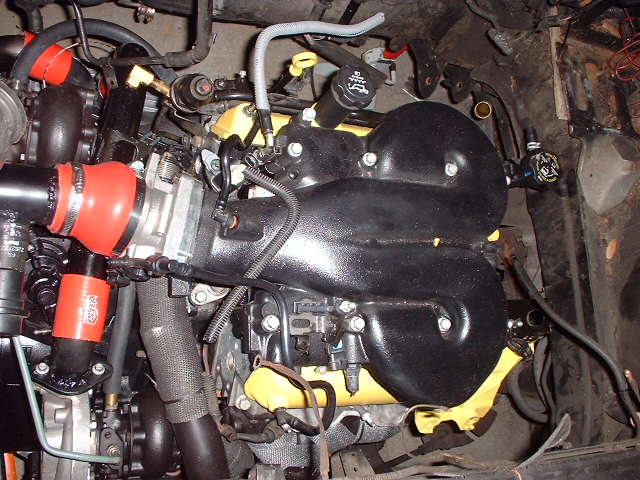
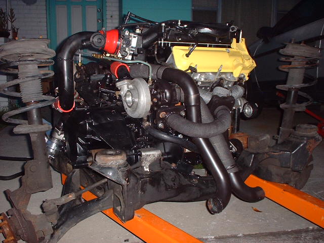
It's in and there are some clearance problems, although it's a 60 degree engine I believe it's a little wider than the 2.8L and the aluminum heads being very different than the previous aluminum heads didn't help, I positioned the exhaust manifolds briefly by holding them against the iron heads on the engine that was in the car so that's where the problem started. I'm trying to decide whether to notch the aft firewall where the problem is, or slot the mount holes and try to move the drivetrain forward about a half inch, then again unbolting it and sliding it forward to allow the rear cradle pads which are only about 1.5" from the mount to swing into position, that might allow room for the manifold flange to clear with the engine moved back into the original mount position.
I also had to cut one of the exhaust pipes off which also interfered with the rear firewall, once the cradle is swung all the way up I should still have room to run it out the back.
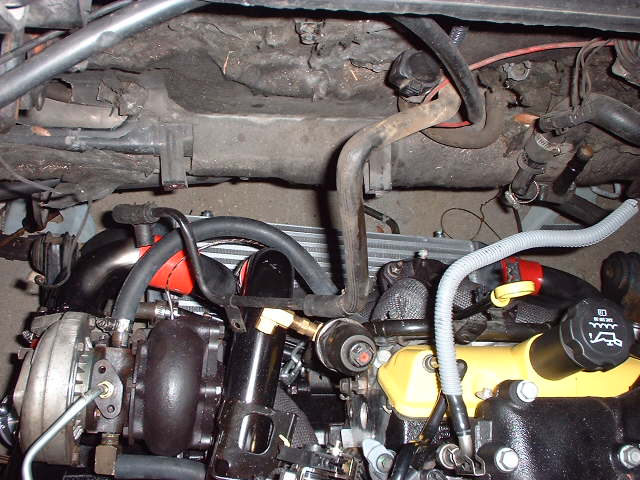
Then there is the water neck that needs to be accomodated, I'm going to try turning it 180 degrees to see if it will clear, otherwise I'll need to fabricate an offset extension
With the water neck removed it seems to fit just fine with the only obstacle preventing completely closing the trunk being the front hoist mount which can be unbolted and removed.
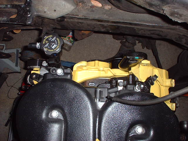
There is one thing left that's going to call for some creativity and that's the alternator, I haven't put it near the mount to assess the conflict but I may have to cut some of the strut tower metal and reinforce it for clearance.
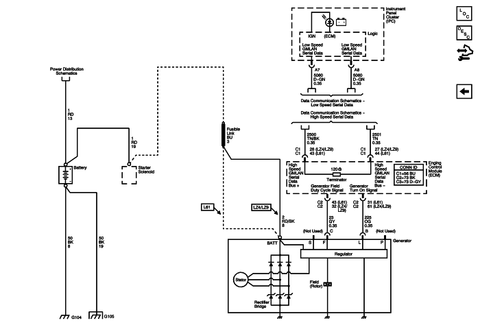
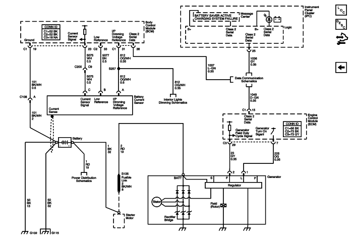
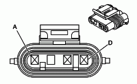
When the engine is running, the generator turn-on signal is sent to the generator from the engine control module (ECM), turning on the regulator. The generator's voltage regulator controls current to the rotor, thereby controlling the output voltage. The rotor current is proportional to the electrical pulse width supplied by the regulator. When the engine is started, the regulator senses generator rotation by detecting AC voltage at the stator through an internal wire. Once the engine is running, the regulator varies the field current by controlling the pulse width. This regulates the generator output voltage for proper battery charging and electrical system operation. The generator F terminal is connected internally to the voltage regulator and externally to the ECM. When the voltage regulator detects a charging system problem, it grounds this circuit to signal the ECM that a problem exists. The ECM monitors the generator field duty cycle signal circuit.
. . .
2007 Chevrolet Uplander
Engine Control Module (ECM) The ECM directly controls the generator field control circuit input to the generator. It monitors the generator's generator field duty cycle signal circuit and sends the information to the BCM. The ECM will override the BCM control of the generator when one of the following conditions is met: The engine control module (ECM) controls the generator through the generator field control circuit. It monitors the generator performance through the generator field duty cycle signal circuit. The signal is a pulse width modulated (PWM) signal of 128 Hz with a duty cycle of 0-100 percent. Normal duty cycle is between 5-95 percent. Between 0-5 percent and 95-100 percent are for diagnostic purposes. The following table shows the commanded duty cycle and output voltage of the generator:
Commanded Duty Cycle.... Generator Output Voltage
10%..................................11 V
20%..................................11.56 V
30%................................. 12.12 V
40%..................................12.68 V
50%................................. 13.25 V
60%..................................13.81 V
70%................................. 14.37 V
80%..................................14.94 V
90%................................. 15.5 V
The generator provides a feedback signal of the generator voltage output through the generator field duty cycle signal circuit to the PCM/ECM, this information is sent to the body control module (BCM). The signal is a PWM signal of 128 Hz with a duty cycle of 0-100 percent. Normal duty cycle is between 5-99 percent. Between 0-5 percent and 100 percent are for diagnostic purposes. --------------------------------------------------------------------------------
[This message has been edited by AJxtcman (edited 09-12-2007).]
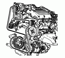
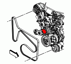
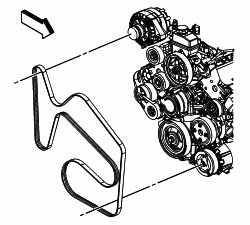
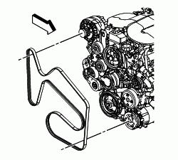
That's waaay too much information for my situation right now, I need the G6 belt diagram because the G6 does not use a power steering pump such is the case with my install. If there is a simple way to make the alternator work the way the Fiero alternator does that would help tremendously because I'm not using the 3900 PCM so the diagrams will not help in this situation. I appreciate it though.
It looks like I can get away with using the 3.5 Malibu belt with the EPS system correct?
[This message has been edited by Joseph Upson (edited 09-11-2007).]
I listed 2 different EPS belt routing's. If you look close you will see that 06 has a Cam Actuator. The belt runs just a little different between the 05 and 06. A G6 and Malibu are both Z cars. If I pull a G6 up it will be the same pictures. I was not aware that the used Hydraulic P/S. That is why I listed both. The alternators look to be wired the same. I will look for some more info on Alternators. I remember that they are all the same from 9? up. I think.
It looks like up 05 Grand Am ( N body) uses a CS in 05 they both CS & SG (2.2L). The 05 G6 ( Z body) uses a SG (2.2L) or TG (3.5L) type. It appears to be similar with the L, F, S, P terminals options
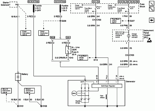
1996 Chevrolet Beretta CS-130
CS-TYPE Generator General Description The CS-type generator uses a internal regulator, which features built in fault detection. The generator used on this vehicle is not meant to be disassembled for service. If the generator becomes inoperative, the generator must be replaced
The CS generator uses a delta stator, rectifier bridge, and a rotor with slip rings and brushes. A pulley and a fan are used to cool the slip ring end frame, the rectifier bridge and the regulator.
This generator may be used with only two connections: the Bat terminal to the battery positive and the L terminal to the charge indicator. The use of the P, F and S terminals is optional. The P terminal is connected to the stator and is connected externally to a tachometer or other device.
The F terminal is connected to the field lead through the PCM and can be used as a system monitor. As the generator load increases, the PCM can adjust the idle speed accordingly.
In this type of circuit, the L can be used to energize the generator. The S terminal may be connected externally to a voltage, such as battery voltage, in order to sense the voltage to be controlled. Refer to Starting and Charging Schematics for complete schematics of the charging system.
As on other charging systems, the charge indicator on the instrument panel will light, with the ignition switch on, and the engine not running. When the engine starts, the indicator light should go out. If the indicator comes on and stays on with the engine running, there is a problem in the charging system. The indicator will glow brightly, no matter what problem it detects. The indicator will also come on with the engine running, if the system voltage is too high or too low.
The regulator voltage setting varies with the temperature. It limits the system voltage by controlling the rotor field current while the field current is on. This regulator actually switches the rotor field current on and off at a fixed frequency of about 400 cycles per second to help control radio noise.
By varying the overall on/off time, the correct average field current for the proper system voltage control is obtained. At high speeds, the on-time may be 10 percent and the off-time 90 percent. At low speeds, with high electrical loads, the on time may be 90 percent and the off-time 10 percent.
[This message has been edited by AJxtcman (edited 09-12-2007).]
S -- goes to B+ F -- goes to switched Voltage ( key on in RUN ) L -- I am not sure if you need this but it goes to the dash light. . . . It looks like you can run Terminal B of the connector / L of the ALT to the Dash light and no other wires will be needed. If it does not turn on you will need to connect F to switched voltage
[This message has been edited by AJxtcman (edited 09-12-2007).]
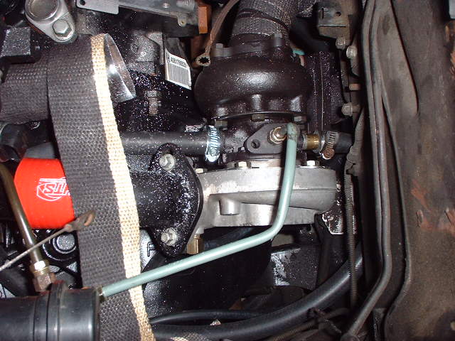
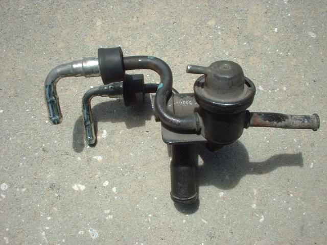
I got the returnless fuel line setup with the adjustable regulator I had to cut from a GM 8100 fuel rail, It's the only method of doing this I'm aware of without a custom part to avoid an in tank adaptation of another system. You have to be careful removing it from the rail because I knicked the bowl on the first one while cutting and found out the hardway galvanized steel is very, very hard to seal small holes on, I did it but it was such a mess I decided not to use it:
It fits pretty well.
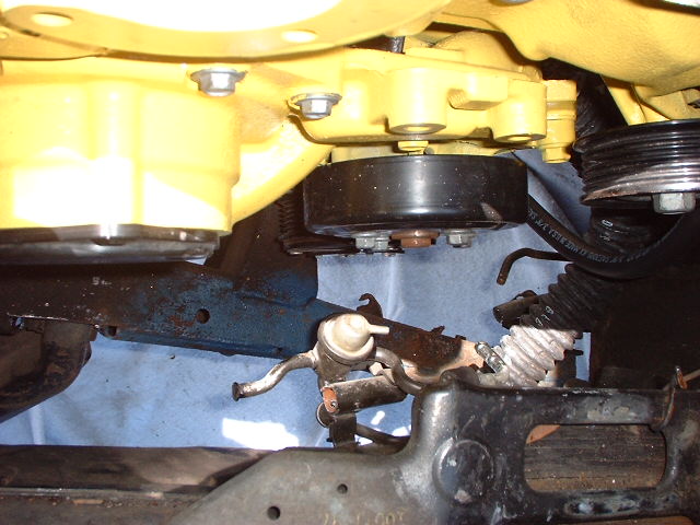
I also got the water neck interference problem worked out by cutting out a diamond with the plasma cutter and welding a neck onto it then attaching then connecting the water neck with a short piece of radiator hose to avoid unnecessary modifications.
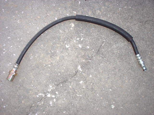
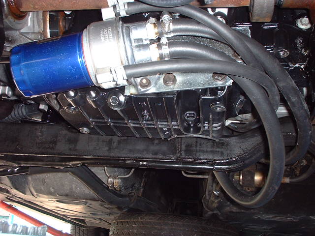
Last but not least is the hydraulic line adaptor for interfacing the 6 spd tranny with the Fiero hydraulic line. Amazon hose put a fitting on the end of the OE G6 hydraulic line for about $8 dollars, then hosed me by charging an average of $6 a foot for 6 ft of fuel hose I just knew wouldn't cost more than about $2 a foot. They don't have prices on anything and the way it's setup you go to the shop they cut or make what you want and then send you to the cashier with a card with some numbers written on it that translate into to a price you are not aware of until it's too late to change your mind. They can take an EXTREMELY long time to get service if there are 2 or more customers ahead of you so you have to ask yourself if you want to take a moment to go get a price quote and end up waiting more than an hour for service or take a chance. It'll be the hour next time because I didn't need as much hose as I purchased so that was a waste of nearly $30.
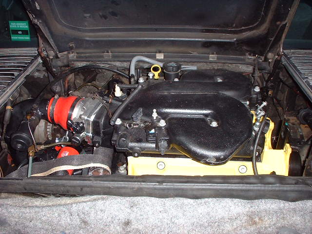
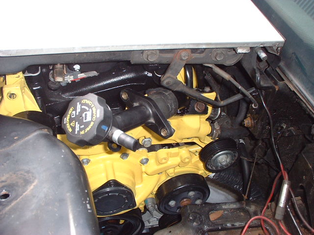
I mounted the oil filter on the back of the oil pan and for the time being will be using the stock sandwhich oil cooler since I have neither the time nor space at the moment to fit my 400 hp rated cooler which I'm thinking about putting up front since Porche did it. The oil pump is bigger than the stock pump in the earlier engines so I'm certain it has the capacity but I would like to test it normally first.
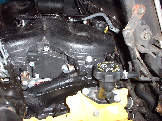
Joseph: This might be a little off subject but is the 3500 and 3900 intakes interchangable. Which is better in your opinion. Well mainly the UIM interchangable. I guess I like the looks of the 3500 intake better.
------------------
85 GT 3.4 14.9 @ 90 1.9 60' Old TH125/3.06 Unknown New 4T60/3.42
Joseph: This might be a little off subject but is the 3500 and 3900 intakes interchangable. Which is better in your opinion. Well mainly the UIM interchangable. I guess I like the looks of the 3500 intake better.
The VVT 3500 intake is interchangeable with the 3900 from what I was told, I have no test to prove which is better, only the dual function of the 3900 manifold which may or may not offer more power up top depending on where the bias is; peak flowing manifold modified to give low speed improvement or moderate performing manifold modified to give better top end based on the intake vain positioning.
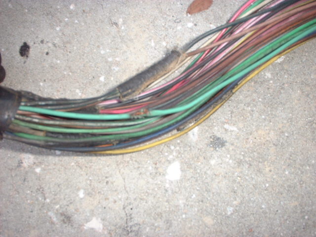
Found some damage to a ground wire tucked away in the harness while hacking it up to suit the 3900, I was stopped short of powering up the system today so that I could interface the laptop with it to check for prescence of all sensor readings by a fierce rain storm.
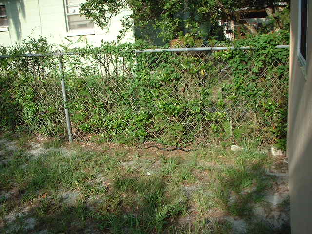
On a previous day I stumbled upon this in the backyard, there are lizards all over the place so black racers are a common site. They're pretty harmless but will bite like mad if you grab one without restraining its head. It's a good size relative to the fence post.
Powered up the system and have some preliminary issues to address. Using the 730 ecm. I did get an engine light flash on ignition Grounded diagnostic terminals gave code 12 and a 34 which I believe is associated with the MAP sensor that's not connected
Problems so far:
No fuel pump cycle Grounds for MAP and TPS are mis matched which may not be a problem but will be corrected. Pink wire from junction block to Fiero coil is supposed to be B+ I believe but is actually grounded since the multimeter measures 12V when it is probed against the battery positive. This wire now supplies the DIS ignition module and coil pack.
Going to remove the harness and back probe every sensor pin assignment which I should have done before ever putting it in the car in the first place.
Good luck getting the wiring straightened out! You've got an awesome build here. I can't wait to hear that it is running.
By the way, do you happen to have any more pictures of the upper intake manifold, particularly from the bottom when you had it off the LIM? I'm curious about the design of the thing and how it compares to the LY7's intake manifold.
You may have to remind me later about the intake, it is similar in form to the 3500 intake on the bottom curving downward toward the lower manifold in the same manner that the oil shield on the bottom of the 2.8 fiero's lower intake.
I'm in the process of wrapping the harness back up and putting it back in the car after the corrections, I didn't find a reason for the fuel pump not to pulse on and when I plugged the harness into the ecm and powered it up out of the car the pump relay came on making a buzzing noise continuously instead of a 2 sec on then off cycle so hopefully that's because it's not in the car connected to everything because it didn't do it while in the car. It does confirm power to the relay though.
Corrected the problems except for the B+ power source to the coil, I'm not sure where it came from previously. I thought it was the pink wire but that wire is actually a ground that can be probed at the C203 plug.
Although I haven't confirmed it I believe the pump failed to run because I was bypassing the battery cable which was not connected to the junction block therefore there was probably no power to the pump. I did confirm a 2 sec relay energize and 12v at the pump harness but the battery charger might not have been strong enough to power it up since the max amp load it produces is 6 and that might have been used up by everything else.
I was rained out again so the start attempt will have to wait another day.
I have ignition fire. Still have a lot of small loose ends to tie up so I'll try to get an early start tomorrow morning to see if It will actually run. At the moment I have a 91 Lumina chip in it to simplify things. I have to add a vacuum fitting to connect the wastegates and MAP sensor, reinstall and bleed the clutch master cylinder, install the intercooler, finish the exhaust, build an air filter system, replace a bad ball joint so in a nut shell it will not be ready to go back to Atlanta with me but if I can get it to run that will be triumph enough.
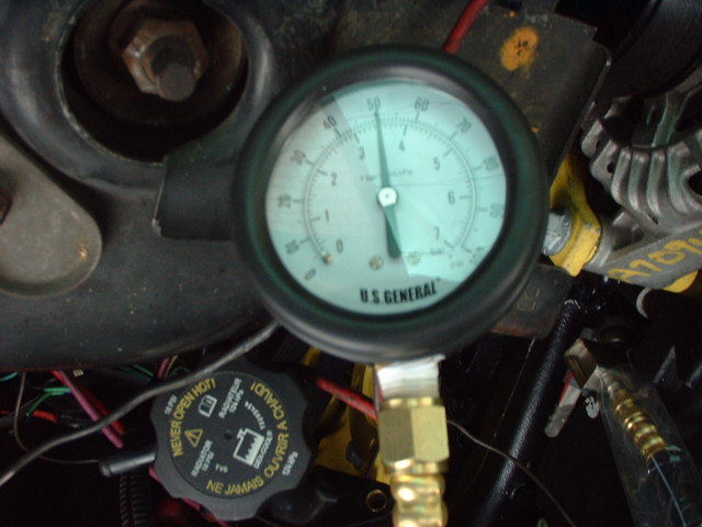
Fuel pressure is testing good. Initially pressure climbed as high as 70 psi but that was apparently because the regulator was stuck. After a muggled snapping like sound followed by a woosh the pressure dropped to where it is now in the picture 50 psi and that's where it hoovers on power up.
"Last but not least is the hydraulic line adaptor for interfacing the 6 spd tranny with the Fiero hydraulic line. Amazon hose put a fitting on the end of the OE G6 hydraulic line "
Where did you get the hose end fittings for the hydraulic line to adapt the 6 spd tranny with the Fiero? Are this fitting part of the OE line for the G6, if so it would require you to buy the clutch master cylinder set?
The flex hose was from a wrecked vehicle and is probably the same on the Cobalt and Ion and can be purchased from GM parts direct I believe. You can actually make two adaptor hoses from one by cutting it in the middle.
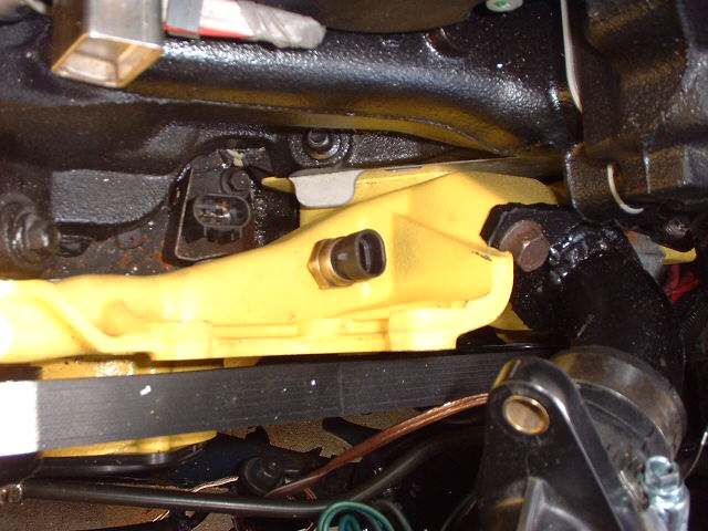
Update, the pump wasn't running because the battery feed to the harness had not been connected. The engine started and ran twice though sporadically which I expected since there are several vacuum points at the manifold that were open at the time. It then proceeded to try and run without the use of starter fluid which suggests it may need more cranking fuel. I advise against the use of starter fluid because even with a cautious approach I still got an explosion through the intake fortunately relieved some by vacuum ports being open like the one for the brake booster. Then it stopped responding altogether, after hours of frustration and the rain coming in on my parade for about the 4th day straight I finally discovered that the crank sensor had stopped working and that's why the gas I was throwing in the intake was not making a difference.
I'm back in Atlanta now and will not be able to take another shot at getting it to run until somewhere around mid October. I believe it will fire right up with the crank sensor taken care of and all of the vacuum ports properly connected so that sensor input matches air flow. I ran out of time before I could replace the crank sensor. It was chopping during the run but since my cam specs indicate a 114 deg LSA that may have been the result of poor injector firing from needing to be loosened up after sitting for so long. I tested one of the extras from the set of 8 and it was clearly not opening properly and had to be tapped and lubed with a little penetrating oil before it started to snap open like it was supposed to.
The injectors are from a GM big block 8100 that were take offs for an alternative fuel conversion but it's possible they were subjected to the different fuel which I think was ethanol before they were removed in which case they could be damaged. I checked the used one against a brand new one of the same application and the difference was undeniable.
The stock injectors are ~28 lb/hr at 400 Kpa and the ones installed are 30 lb/hr at 300 Kpa so at the higher fuel pressure of the OE injectors I should be pushing at least 32 lb/hr with a max of around 35-36 lb/hr under boost compounded with the base rail pressure set at 60 psi since GM runs about 56 psi on the 3400 and 3100 cars.
I'm also still working on getting an ALDL connection with the Moates Autoprom which appears to emulate okay but has yet to connect via ALDL connection so I can get my sensor readings and make sure they are all in spec and connected properly.
I notched the deck lid to clear the alternator wasn't to bad, I'll patch that area later, now the decklid closes.
[This message has been edited by Joseph Upson (edited 09-27-2007).]
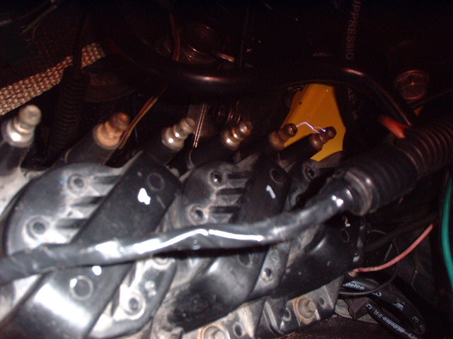
I finally succeeded in getting it to run although not 100% yet. It's firing cylinders on both banks but at least one cylinder possibly two is/are not firing. The turbos spooled up a bit and made a nice harmonious sound. I decided at that point to focus on getting the car put together starting with completing the exhaust and then installing all of the inlet plumbing so I can focus on tuning. I'm hoping it's either a bad coil or ignition module or something simple over all. I changed out the coils but haven't attempted to restart the engine to hear the results.
I'm currently working with the A1 Beretta 3.1 code for simplicity. Since it uses 16 lb/hr injectors the 30 lb/hr injectors installed were flooding the engine causing hard starts requiring clear flood starts and then choking it out afterwards. Reducing the base pulse constant and advancing the base timing by 10 degrees helped get it started. The hard start remained because I needed to adjust the coolant temp vs. cranking pulse width.
I believe when I switch to the TGP code it should be a little easier to crank and run since the Turbo Grand Prix used ~24 lb/hr injectors and when scaled to match the same engine increased to 3.9L the proper injector to displacement ratio called for 30 lb/hr injectors which are already installed.
Hopefully the coil swap will solve the misfire problem after which I should be able to post some video.
[This message has been edited by Joseph Upson (edited 10-23-2007).]
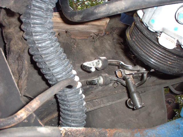
The 2.8 has 3 coolant sensors, the 3900 only has one since no coolant flows through the intake manifold. The coolant holes are not the same at both ends of the head and I didn't want to add an additional hole or enlarge the current to fit the 3 wire sensor that would supply a signal to the gauge and the ECM. I installed another of the smaller temp sensors in the coolant crossover pipe on the front of the cylinder heads. I can use the larger tap in the picture to install the Fiero's gauge and hot light sensor later but hopefully I can find an extra programmable terminal on the 730 to trip the hot light in the event of an overheat.
The three wire sensor from Advance 38-5124, $13, and the tap from NAPA $7 3/8" pipe thread if you decide to go this route.
The smaller sensor went in place without a problem and it's close to the coolant wires coming out of the junction block.
Once I install the intercooler and secure everything from heat and schaffing I should be able to get back to solving the misfire problem.
I finally hit pay dirt, I had to use a digital photo camera to record video from which I lifted the audio, the microphone couldn't handle the raspy exhaust note so you'll hear popping throughout. It was running off the Berretta 3.1 code, and very rich at that where it was choked out toward the end of the sound clip on a reve attempt. Later I was able to get the 8F TGP code to work in the Moates emulator however, I couldn't get the ALDL connection I needed. As expected the engine ran much better with the TGP code which uses ~24 lb/hr injectors instead of the 16s in the Beretta code which really threw the fueling off since the flow was near double with the 30lb/hr injectors installed. With the TGP code a lot of the rasp disappeared and hopefully when the glasspacks go on tomorrow it will mellow it out more.
This is a link to my old website to get the sound clip, don't mind my rhetoric, look under the picture of the dog; https://publish.att.net/wsb-cgi-bin/view.cgi/home.html?wsbID=164623
would love to hear it , but you have the file set as private . I cant login to your att account and get it
Sorry, no one said anything until now, I'm not sure what's going on with the webpage, I never put a password on it so it must be a fall out from the changes the IP provider made to the personal web page section. You can find it attached to a post here . about 5 posts down. http://www.60degreev6.com/s...d.php?t=37902&page=4
I used a digital camera which apparently has some difficulty with recording the engine tone due to its sound or there's a problem with the camera. It's open exhaust on the clip and sounds a little radicle because of the rich tune. Later I installed the glass packs at the tips instead of where they were located in the pictures due to space constraints and I didn't like the way they sounded at all, they weren't loud but because they are about 4" in diameter there was quite a bit of scavenging interupting the exhaust note, I could put my hand over the tip and it would blow it away then suck it back over the pipe during idle.
Turbos generally quiet down an open exhaust system but not twin turbos, it's much louder than any single turbo that I've run without a muffler, so i'll be installing two small mufflers in place of the glasspacks for better harmonics.
I tweaked the tune enough to go for a test drive but before I could get out of the driveway I failed to realize that the rear caliper I replaced although it had some brake fluid in it was fully retracted on install so all though I attached the hose quickly so that not much brake fluid was lost the system would still need to bled which I'll have to loosen the hose at the caliper to do since the bleed screw is seized in place. I popped the clutch just a little and the car jumped since the drivetrain is solid mounted then I hit the brakes only to find there were none. I stopped it without a major problem.
I'm back in Atlanta so it will be about 5 wks before I can get back to fix the exhaust, two oil leaks (oil return flange, possible oil filter seal) the brakes and install the air filter plumbing. I was really tired of it when the test drive attempt was haulted because of the brakes. I'll also have to install restrictors for the oil feed to the turbos because high revs caused some smoking and I suspect the oil pump which is larger than previous versions must be producing pretty good pressure to force oil past the seals on a pair of turbos.
If I had it to do all over again I would do a single turbo, some times novelty is over rated.
Earlier you said you had a miss in one or two cylinders. Did it turn out to be a miss or was it the tuning issues?
It was a bad coil pack. It runs pretty solid but needs to be driven for further tuning. Sometimes it idles about as low as a Harley Davidson, so low that the dampened 6spd flywheel starts to oscillate and cause transmission noise. The PE vs TPS% table is where to go in the chip when you have black smoke puffing out the tailpipe on opening throttle. I lowered the entire table and the black smoke disappeared, then I started adding fuel back to it when it dropped off in the higher rpm. I did some WBO2 logging with my Zeitronix unit and measured AFR spikes as high as 21:1, that thing is a God send.
I haven't been able to get the Moates APU-1 emulator to do its job properly and that's been pretty disappointing given what it cost. I haven't heard from Moates either regarding an email sent Sunday asking for guidance. Oh well.
[This message has been edited by Joseph Upson (edited 11-01-2007).]
I just went to the Moates website to email another request for guidance with the emulator and discovered that the Ostrich emulator a less expensive model has been discontinued, it was just resently upgraded. It's not looking good for any hope of getting my situation resolved. $325 plus another $35 or so in accessories and it has yet to do what I primarily purchased it to do. When you buy things like this make sure wait until you are ready to use it so the warranty doesn't run out while you are waiting only to find there is a problem after the fact.