I am going to be making an adapter for a Northstar engine and need to know if it has the same bolt pattern on the bellhousing as the GM metric pattern that the Fiero engines use. If anyone had done a swap with a Northstar engine and can tell me about this please let me know.
Yes! Sort of!! All the N* bolt holes line up with any stock Fiero transmission except one. If you do some searching in the Construction Zone you'll find what many have done to make even that one line up.
I am going to be making an adapter for a Northstar engine and need to know if it has the same bolt pattern on the bellhousing as the GM metric pattern that the Fiero engines use. If anyone had done a swap with a Northstar engine and can tell me about this please let me know.
Why the N*? There r tons of better engines to choose from.
Why the N*? There r tons of better engines to choose from.
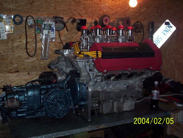
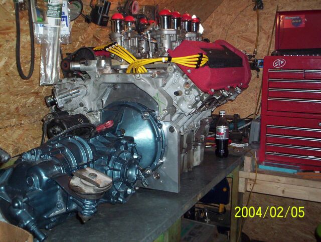
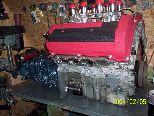
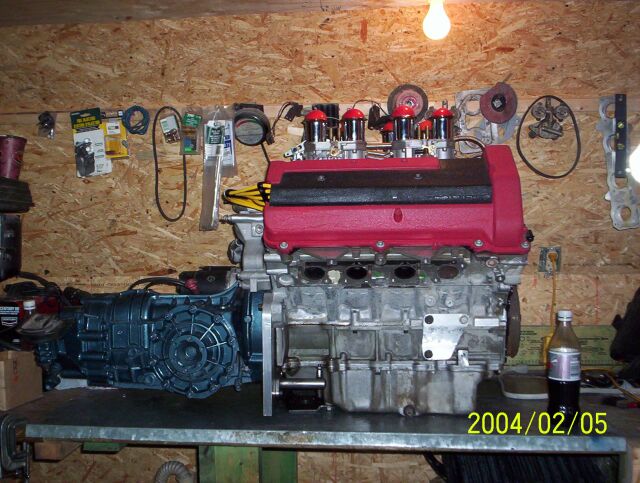
That is what my customer wants to use so I will do what is necessary to fit it. It is going in a stretched chassis in a longitudinal position with a Porsche transmission.
I am going to be making an adapter for a Northstar engine and need to know if it has the same bolt pattern on the bellhousing as the GM metric pattern that the Fiero engines use.
4 of the 6 holes are in the same location, one hole was never drilled/not used, but the 6th hole was moved to clear the 4T80 transmission. Blooze does an excellent job showing this relocated bolt and how he got around it.
quote
Originally posted by Bloozberry:
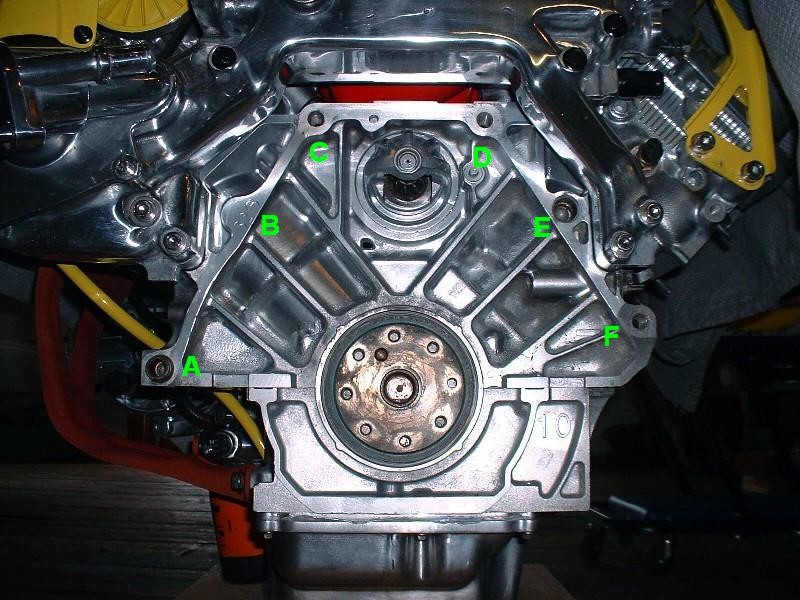
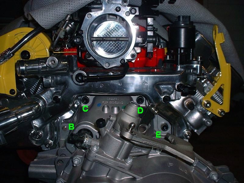
Now back to the transmission-to-engine mounting fun. Anybody who’s swapped a Northstar already knows the basic issues with mating one up with a standard GM Metric bellhousing pattern, but for those who aren’t familiar, this post is for you. For starters, here’s the rear view of the N*:
I’ve labeled the six locations for bellhousing bolts to illustrate which ones need massaging for the F40 transmission. The problematic holes are B, E, and F. Unfortunately there’s not much that can be done about mounting hole B. It’s not drilled or tapped on the N* for good reason. There simply isn’t enough depth of material between the bellhousing flange surface and the side wall of cylinder #8. It may be possible to safely drill and tap the location up to 3/8 of an inch deep, but then it wouldn’t serve much purpose, and it would more likely distort the cylinder wall or pull the threads out if any amount of torque were applied. Hole E is simply an unthreaded hole with an alignment dowel pressed into it, so it can’t be used as is to secure the transmission. The hole is waaaay larger than the M12 bolts used to mate the transmission to the engine. Finally, the problem with hole F is that the hole in the transmission bellhousing doesn’t line up with hole in the engine block.
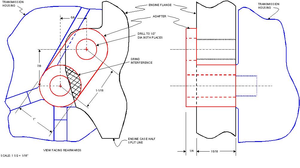
I started by addressing hole F. First, with the transmission mated to the engine, I drew out the dimensions of the two holes in relation to each other. This was an extra step I took so that anybody doing this in the future can design their own coupler with the key dimensions from the drawing. After some research, I decided to follow a similar (though not identical) design that PFF member “buds” used here, about 2/3 of the way down the first page www.fiero.nl/forum/Forum2/HTML/088691.html Note that regardless what design you use, there will be a need for some grinding on the engine flange since it covers a small arc of the actual bolt hole on the transmission.
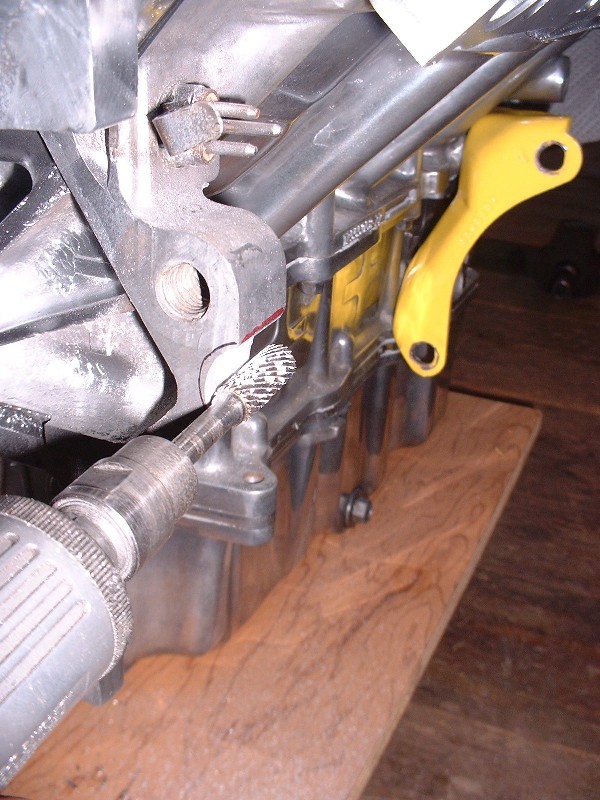
With my drawing in hand, I transferred the dimensions of the larger area I wanted to grind off the engine flange onto the flange itself. This is the view looking rearwards. (I traced the cut-out electronically onto the photo because there were too many reflections to see them properly in the photo.)
Then I used my handy grinding burr to remove the excess material. It ground down surprisingly easily, though I had to stop a few times to clean the bit to keep it from galling.
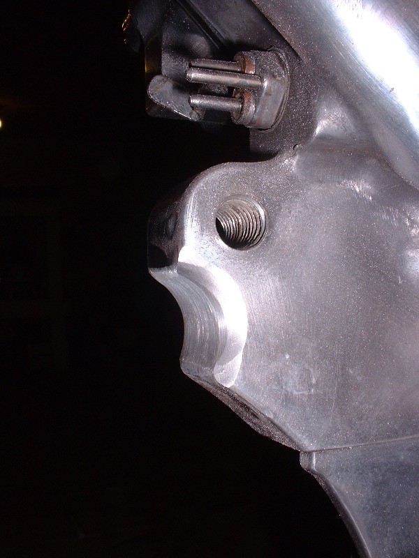
And here’s the finished product, although I had to make a few minor adjustments later on, which I’ll describe later.
Next I needed to make my adapter. I started out by cutting a 1-3/16” length of 1” diameter steel rod. It goes amazingly fast with the right tools!
Then I fabricated the flat portion out of ¼” steel plate, drilled the 1” diameter arc using a hole saw, and finished by beveling the edges for good welding penetration. Here are the two pieces clamped in the vise ready to be fused into a single piece.
A quick zip-zap with the MIG welder on the inside and outside of the mating surfaces.
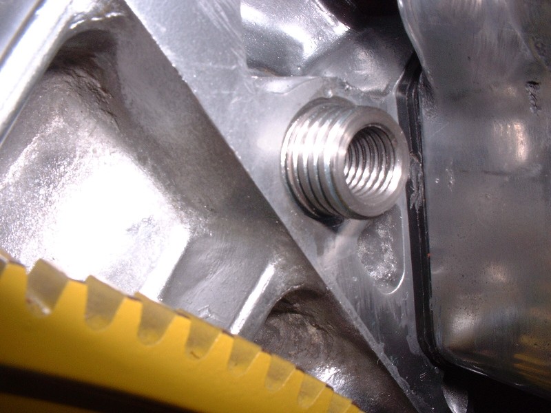
… and here’s the finished product once the welds were ground down smooth, and after a quick trip to the lathe to drill the 1/2" diameter hole through the center of the rod. The inside filet is the reason I needed to make a few adjustments to the engine flange notch. To make the adapter sit properly, I needed to grind a beveled edge on the flange.
The moment of truth actually took a few test fittings since I found I hadn’t ground away enough aluminum from the flange even after beveling it. No biggie. To install the adapter, I used an M12 X 1.75 X 70 (12.9) in the lower hole, and an M12 X 1.75 X 35 (12.9) in the upper hole.
Edited to change bolt lengths used.
quote
Originally posted by Bloozberry:
Next up was to figure something out for hole E. I did a bunch more research here on PFF but couldn't find anyone who had used this hole for a bellhousing bolt. Again, the problem with this hole is that there’s an alignment dowel pressed into it, but the inside diameter is not threaded at all. To make matters worse, the alignment dowel is pressed in very tightly making its removal very difficult. At first I tried the same method I used to remove the cylinder head dowels by shoving a steel rod down into the ID of the dowel to prevent the sides from collapsing as I tried clamping and turning the dowel with Visegrips. It wouldn’t budge and ended up galling up the sides of the dowel. I didn’t think of taking pictures at the time since I didn’t think removing a dowel would be worthy, but I took some afterwards given what I had to do to get it out.
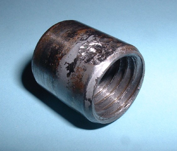
After some measurements I found that the ID of the dowel was just about right to cut some 5/8” threads into it, and I happened to have the 5/8” X 11 tap handy from when I used Norm’s head bolt insert kit. So at first I thought I would just tap the OEM dowel ID, and up-size the bellhousing bolt to 5/8”. But then I realized that wouldn’t provide any clamping force because the dowel isn’t mechanically locked to the engine block except through an interference fit. But it did give me an idea on how to go about removing the dowel, so I tapped the ID anyways. Here it is mocked up with the tap after I actually got it out.
Then, using a spare insert from Norm’s headbolt insert kit (he sends you 21, but you only need 20), I threaded it into the dowel, and then threaded one of the used head bolts into the insert.
Finally, using a slide hammer under the head of the bolt, I was able to pull that sucker out of the block. What a PITA!
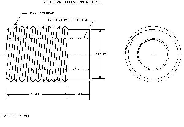
Now to make hole E useful, the idea was to fabricate a new alignment dowel that was threaded both on the outside diameter to lock it to the block, and on the inside diameter to allow a standard M12 x 1.75 bellhousing bolt to be used to bolt the tranny to the block. I drew out a schematic of what the new threaded alignment dowel should look like with the appropriate measurements so you don’t have to go through it all yourself:
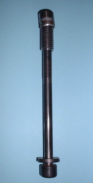
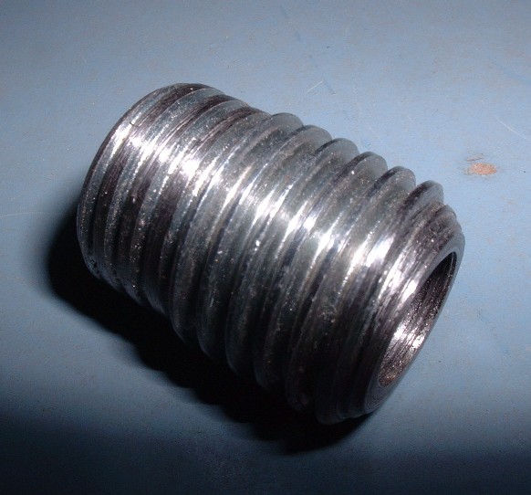
To make it, I bought an M20 X 2.0 X 60 bolt ($3) and had a friend with a machine shop remove the head, then machine the threads off one end along an 8 mm length to a new OD of 18.5 mm, which is equal to the OD of the OEM dowel. You’ll notice from the picture that it didn’t end up removing the entire depth of the threads, but that doesn’t matter. This will be the end that will stick out of the block. Then he drilled and tapped the core of the new dowel for the M12 X 1.75 bellhousing bolts, and finally cut it to the correct overall length.
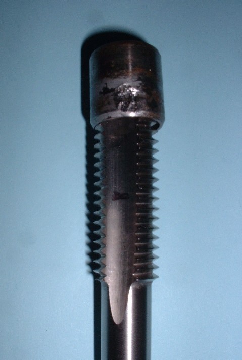
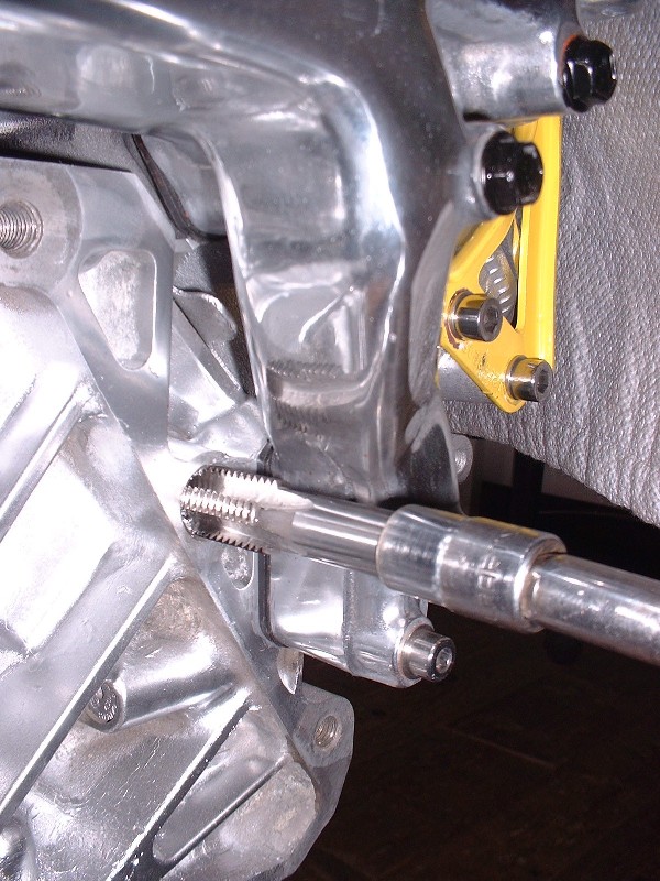
Next step was to tap the engine block where the old dowel was. The hole, as mentioned before, is 18.5mm in diameter, so that’s why I went with the 20mm bolt for the new dowel. I bought an M20 X 2.0 end tap ($36) and threaded the engine hole without any problems.
Just be careful if you do this not to over torque the tap as you reach the bottom since you risk stressing the cylinder wall.
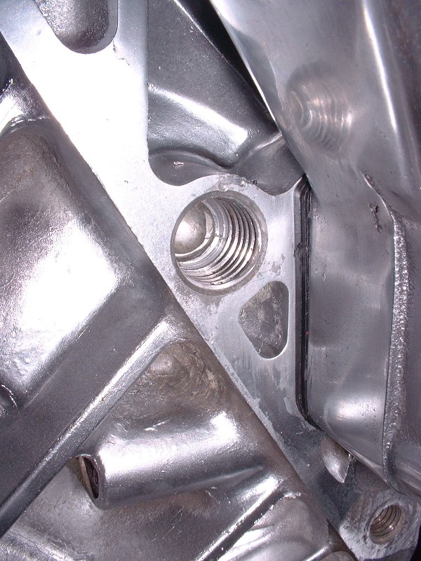
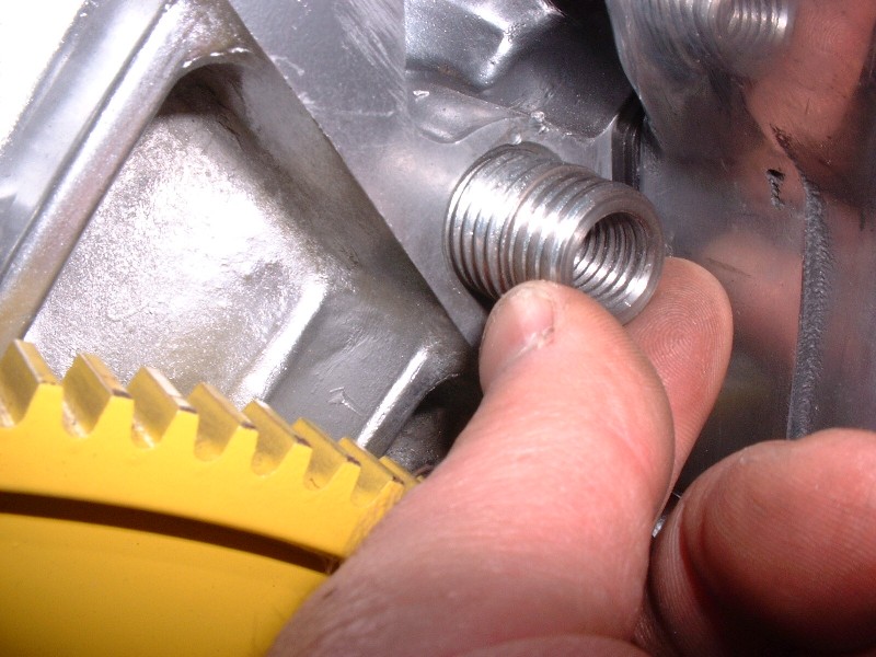
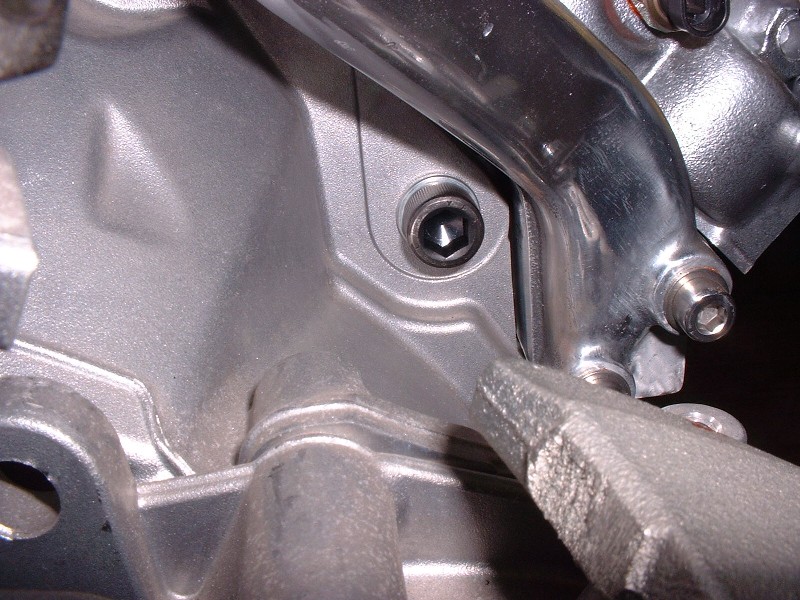
The rest was a walk in the park. I just screwed the new threaded alignment dowel into the block (I’ll use thread locker for the final installation later on).
Make sure that the OD threads of the dowel are completely recessed into the block and that the only part protruding is the part that the threads were shaved off:
And install the transmission.
I used the following length M12 X 1.75 bolts in the locations identified in my last post: A = 50mm, B = nothing, C & D = 70mm, E = 30mm, F (top) = 35mm, F (bottom) = 70mm.
[This message has been edited by fieroguru (edited 06-07-2014).]
That is what my customer wants to use so I will do what is necessary to fit it. It is going in a stretched chassis in a longitudinal position with a Porsche transmission.
Then why are you even asking about Fiero transmissions? The Porsche trans and Northstar use different bell patterns. You will be making an adapter.
Then why are you even asking about Fiero transmissions? The Porsche trans and Northstar use different bell patterns. You will be making an adapter.
There are adapter plates to go from GM Metric bellhousing to Porsche Transmission. He probably wants to know how hard it would be to adapt one of these to his N*/Porsche application vs. making a new one.
It could also be that he found the GM Metric bellhousing drawing with the dimensions of the holes and wants to know if this will work for his N* adapter plate.
[This message has been edited by fieroguru (edited 06-07-2014).]
There are adapter plates to go from GM Metric bellhousing to Porsche Transmission. He probably wants to know how hard it would be to adapt one of these to his N*/Porsche application vs. making a new one.
It could also be that he found the GM Metric bellhousing drawing with the dimensions of the holes and wants to know if this will work for his N* adapter plate.
I have made adapters for engines with the GM metric pattern (Fiero and LS4) and just wanted to know if the N* had the same pattern. There are some wonderful threads here with the information I need so this will be very helptul and I thank everyone who replied.
That is what my customer wants to use so I will do what is necessary to fit it. It is going in a stretched chassis in a longitudinal position with a Porsche transmission.
Do u have a shop in the Dallas area? I thought I knew most of the Fiero based swappers.
Do u have a shop in the Dallas area? I thought I knew most of the Fiero based swappers.
Yes, I have a shop here. I don't do much Fiero stuff, mostly chassis for VW based kits and adapters for various engines to Audi and Porsche transmissions. www.kitcarchassis.com
Yes, I have a shop here. I don't do much Fiero stuff, mostly chassis for VW based kits and adapters for various engines to Audi and Porsche transmissions. www.kitcarchassis.com
I am not far from the guy who had Fast Fieros.
Cool deal....Might need some machine work done in the future..