Pennock's Fiero Forum
  Technical Discussion & Questions - Archive
  DIS Pick Up Coil Wiring 60° V6

T H I S   I S   A N   A R C H I V E D   T O P I C
  

Email This Page to Someone! | Printable Version


DIS Pick Up Coil Wiring 60° V6 by phonedawgz
Started on: 04-06-2012 10:51 PM
Replies: 11
Last post by: phonedawgz on 04-11-2012 10:02 AM
phonedawgz
Member
Posts: 17091
From: Green Bay, WI USA
Registered: Dec 2009


Feedback score:    (23)
Leave feedback


Total ratings: 290
Rate this member

Report this Post04-06-2012 10:51 PM Click Here to See the Profile for phonedawgzClick Here to visit phonedawgz's HomePageSend a Private Message to phonedawgzDirect Link to This Post
The pick up coil of the 60 deg V6 wires to the three pin connector on the DIS block.

I have bone yard connectors that are A-B and I have some that are A-C.

When is each used?

No by the way - the actual crank pick up is a two pin connector.

IP: Logged
PFF
System Bot
Blacktree
Member
Posts: 20770
From: Central Florida
Registered: Dec 2001


Feedback score:    (12)
Leave feedback


Total ratings: 350
Rate this member

Report this Post04-06-2012 11:05 PM Click Here to See the Profile for BlacktreeClick Here to visit Blacktree's HomePageSend a Private Message to BlacktreeDirect Link to This Post
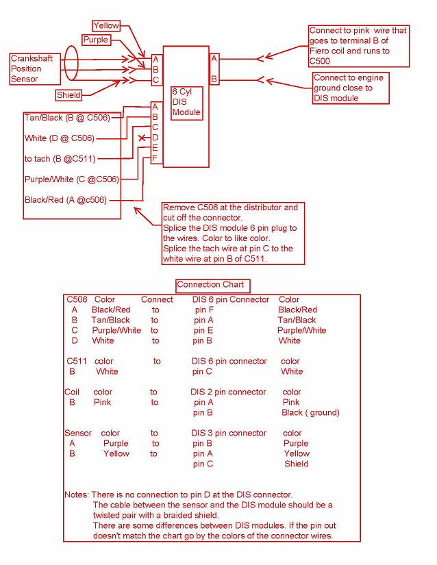
It may depend on the application. But the DIS brick that I have (from a 3100 SFI) uses pins A and C for the crank trigger. According to the schematics, Pin B is an optional (unused) ground, for RFI shielding on the crank trigger wires.
IP: Logged
ConvictedRedneck
Member
Posts: 1034
From: Easton, PA - USA
Registered: Nov 2005


Feedback score:    (7)
Leave feedback

Rate this member

Report this Post04-07-2012 12:09 PM Click Here to See the Profile for ConvictedRedneckSend a Private Message to ConvictedRedneckDirect Link to This Post
I'm curious to this as well...I'll be doing this as soon as I get your connectors, phonedawgz. Did the two different wiring setups use the same sensor? I'd assume they did but just throwing out ideas.

I think the first time I wire it up I'll use A-C. Ryan has that in his wiring chart. However, this chart still has it A-B...


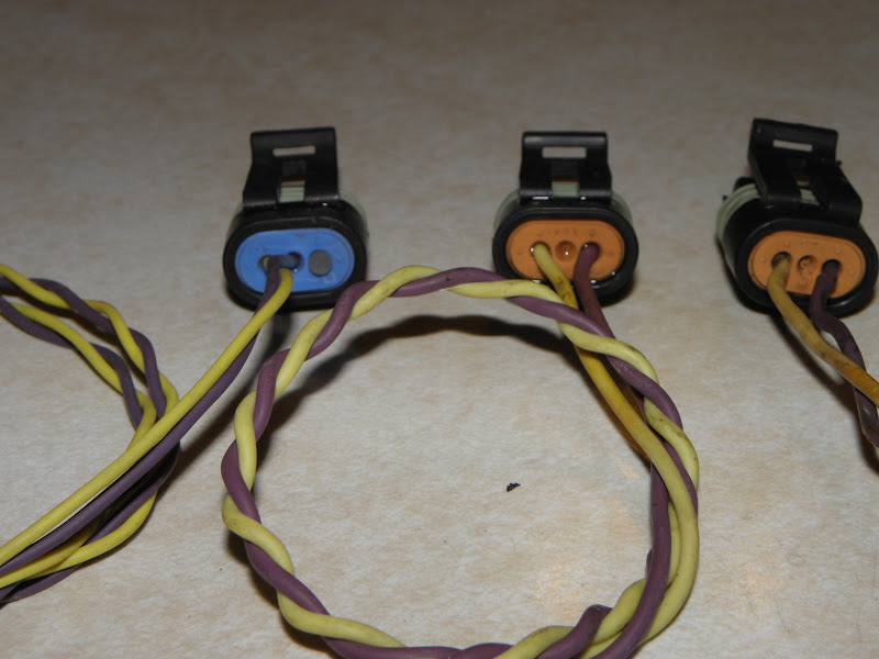
The reason I asked about the sensor type is because the picture above is specifically for using the ford escort sensor per that thread, whereas most other guys are using the GM sensor meant for the 3.4 block.

On a related note, my Ford crank sensor isn't labeled A/B, does it matter which wire goes to which pin on the ignition module?
IP: Logged
Blacktree
Member
Posts: 20770
From: Central Florida
Registered: Dec 2001


Feedback score:    (12)
Leave feedback


Total ratings: 350
Rate this member

Report this Post04-07-2012 05:39 PM Click Here to See the Profile for BlacktreeClick Here to visit Blacktree's HomePageSend a Private Message to BlacktreeDirect Link to This Post
I don't understand why you're adapting Ford ignition systems, when there are so many GM 60-degree V6 engines with DIS as well?

[This message has been edited by Blacktree (edited 04-09-2012).]

IP: Logged
ConvictedRedneck
Member
Posts: 1034
From: Easton, PA - USA
Registered: Nov 2005


Feedback score:    (7)
Leave feedback

Rate this member

Report this Post04-07-2012 07:23 PM Click Here to See the Profile for ConvictedRedneckSend a Private Message to ConvictedRedneckDirect Link to This Post
Since I'm putting DIS on a 2.8, there are no provisions for a GM crank sensor like on a 3.4 (or that's what I was under the impression of). I followed the instructions as outlined here and the design of the ford sensor makes it ideal to use in that application.

IP: Logged
Blacktree
Member
Posts: 20770
From: Central Florida
Registered: Dec 2001


Feedback score:    (12)
Leave feedback


Total ratings: 350
Rate this member

Report this Post04-07-2012 08:59 PM Click Here to See the Profile for BlacktreeClick Here to visit Blacktree's HomePageSend a Private Message to BlacktreeDirect Link to This Post
...and now I understand.

thanks
IP: Logged
neophile_17
Member
Posts: 58
From: Southington, CT
Registered: Aug 2007


Feedback score: N/A
Leave feedback

Rate this member

Report this Post04-09-2012 10:02 AM Click Here to See the Profile for neophile_17Send a Private Message to neophile_17Direct Link to This Post
It is my understanding that it does matter if the crank sensor is wired backwards. The page below is quite long but if you scroll down to where it says:

The following diagram shows what happens when the VR jumpers on the V3.0 PCB or the VR sensor is wired incorrectly:

Then you'll see the explanation of what can happen if the sensor is hooked up incorrectly. That's a missing tooth system instead of a extra tooth system but you can see how things get messed up.

~sam

link:
http://www.msextra.com/doc/...are_Manual.htm#gmdis
IP: Logged
Blacktree
Member
Posts: 20770
From: Central Florida
Registered: Dec 2001


Feedback score:    (12)
Leave feedback


Total ratings: 350
Rate this member

Report this Post04-09-2012 04:01 PM Click Here to See the Profile for BlacktreeClick Here to visit Blacktree's HomePageSend a Private Message to BlacktreeDirect Link to This Post
OK, I'll edit out my incorrect assumption.
IP: Logged
ConvictedRedneck
Member
Posts: 1034
From: Easton, PA - USA
Registered: Nov 2005


Feedback score:    (7)
Leave feedback

Rate this member

Report this Post04-10-2012 07:38 PM Click Here to See the Profile for ConvictedRedneckSend a Private Message to ConvictedRedneckDirect Link to This Post
I'm kinda stuck...the thread I referenced for adapting the 2.8 to DIS using the Ford sensor doesn't mention which pin is which on the sensor and the one I have doesn't have any labeling...

Any way to determine this? Trial and error?
IP: Logged
ConvictedRedneck
Member
Posts: 1034
From: Easton, PA - USA
Registered: Nov 2005


Feedback score:    (7)
Leave feedback

Rate this member

Report this Post04-10-2012 07:46 PM Click Here to See the Profile for ConvictedRedneckSend a Private Message to ConvictedRedneckDirect Link to This Post

ConvictedRedneck

1034 posts
Member since Nov 2005
From a bmw forum using the same sensor...

 
quote
Originally Posted by shauer View Post

As you are wiring up the VR sensor make sure you have the polarity correct. The following procedure is on the 'net at several locations and works well:

Connect the sensor to a digital volt meter and place the meter on the most sensitive DC voltage setting.

Take the sensor and allow it to drop onto a steel object while viewing the meter.

The meter will momentarily register a small voltage (less than 100mv). If the voltage is positive then the (+) lead on your meter is connected to the VR sensor (+) pin. If the voltage is negative then you have your meter probes switched around.

The sensor should produce a positive voltage spike as it transitions from air to metal. Dropping it onto a steel plate is an easy way to do this.

Keep up the great work on this.

- Steve


So assuming I can figure out which pins are positive/negative on the sensor, anyone know how positive/negative corresponds to the wiring at the DIS module?

ETA:
Adding to this, would the positive pin be the 'crank sensor hi' or 'crank sensor low' as labeled in Ryan's wiring chart? I'm inclined to think positive would be 'low' since the low spot in the harmonic balancer is what sensor first picks up and the 'hi' follows the low spot, making it the negative?

...I'm by no means an electrical engineer so this is looking at it from a very mechanical, intuitive perspective.

[This message has been edited by ConvictedRedneck (edited 04-10-2012).]

IP: Logged
neophile_17
Member
Posts: 58
From: Southington, CT
Registered: Aug 2007


Feedback score: N/A
Leave feedback

Rate this member

Report this Post04-11-2012 09:43 AM Click Here to See the Profile for neophile_17Send a Private Message to neophile_17Direct Link to This Post
You're putting too much thought into it. The electrical guys think of high as positive. Even if you get it backwards you shouldn't cause any damage. I didn't anyway.

~sam

IP: Logged
PFF
System Bot
phonedawgz
Member
Posts: 17091
From: Green Bay, WI USA
Registered: Dec 2009


Feedback score:    (23)
Leave feedback


Total ratings: 290
Rate this member

Report this Post04-11-2012 10:02 AM Click Here to See the Profile for phonedawgzClick Here to visit phonedawgz's HomePageSend a Private Message to phonedawgzDirect Link to This Post
If you see a large high speed cut off - try reversing the polarity.

IP: Logged


All times are ET (US)

T H I S   I S   A N   A R C H I V E D   T O P I C
  

Contact Us | Back To Main Page

Advertizing on PFF | Fiero Parts Vendors
PFF Merchandise | Fiero Gallery | Ogre's Cave
Real-Time Chat | Fiero Related Auctions on eBay


Copyright (c) 1999, C. Pennock