It works nicely, however, if my Fiero is typical of all of them (I'm assuming so, seeing as how everything about my Fiero is factory) It's installation is not quite as simple as the instructions they give, and you will actually need a couple extra parts.... Including: A couple lengths of wire (not much, prolly 2 feet), And unless you feel like ruining your lenses, you'll want to pick up a pair of OEM bulb sockets, similar to what you find on your turn signals to replace your inner-most red light. Also, you'll need a pair of resistors, which, is what took me a long time, and a bit of help to figure out.
For some reason, with just the kit they supply you with, when the headlights/running-lights are on, the turn signals fail to sequence. A 20-watt resistor worked fine on the left, But it doesn't seem to be enough on the right, and I haven't quite solved that one yet... Another one should do the job. It has to be installed parallel to the unit, from the power-supply going into the unit, to the grounding point.
Web Electric has kits for the Fiero too. You can find them in the vendor list. I have them on one of my cars very nice. And verything you need is in their kit.
/should/ being the key term... The people at Thundercats couldn't figure it out either... I just need a bit bigger resistor on the passenger side, and I'll be in business, had it working with an extra light wired in in place of the resistor and it worked... the equivolent of 36 watts of resistance. So, another 20 should get me there.
[This message has been edited by Twilight Fenrir (edited 07-31-2009).]
$80, which has the two units, a pair of sockets (that don't work too well for this particular car), a bunch of connectors, the digital solenoid.... plus about $20 for the appropriate light-sockets, and another $4 for the resistors...
Also, I just had a loose connection on my passenger side, just got it up and running now, so I'm all set!
[This message has been edited by Twilight Fenrir (edited 08-01-2009).]
IP: Logged
12:04 AM
brian99 Member
Posts: 38 From: Elk River, MN USA Registered: Aug 2003
I had an old conversion kit from Web Electric with outdated instructions and spent hours trying to get them to work even with using the electronic flasher.
I would appreciate if you would cover in detail what you actually had to do to get your to work. Where did you put the resistors, what was the resistance and ohm ratings you finally used, and how did you wired the module to the existing and new sockets.
I would sure like to get mine to wired up and working, but with out a proven wiring plan I don't think it will happen.
BRIAN
Well... there are a few different systems for making sequential tail-lights... If you've got the two independent units that you install at the taillights, we should be good.
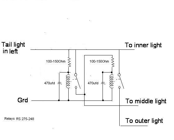
Here's the diagram that came with the kit... slightly edited to include the resistor...
The resistors I used, were 20-watt 8-ohm resistors, I picked up in-stock at RadioShack for about $2 each.
The left-most bulb socket needs to be removed, replaced with one of the same style on either of the outer two... Can pick two up from a parts store, or salvage yard.
[This message has been edited by Twilight Fenrir (edited 08-01-2009).]
IP: Logged
11:36 PM
Aug 2nd, 2009
brian99 Member
Posts: 38 From: Elk River, MN USA Registered: Aug 2003
As can be seen, there are 4 wires of the same color that exit the two sides of the module. In addition there is an additional heavy black ground wire that is present with only 1 side of wires.
I purchased the module from Web Electronics a number of years ago and they have since changed the configuration of the module so it does not resemble the one I have now.
Lawrence at Web Electronics does not respond to the email I sent him so I can't get any help from him. I wonder if he is still dealing with the Fiero market any longer.
Hopefully, someone on the forum has the older module and knows how to wire it into the system.
Adding the resistor should not be necessary if you use a "electronic flasher" I would think. Probably needed with a normal flasher to get enough load maybe.
[This message has been edited by Dodgerunner (edited 08-02-2009).]
IP: Logged
09:11 PM
jsketcham Member
Posts: 434 From: Meadville, Pa, USA Registered: Jan 2009
Adding the resistor should not be necessary if you use a "electronic flasher" I would think. Probably needed with a normal flasher to get enough load maybe.
Again, the electronic flasher was included with the kit, and installed. So, that shouldn't be an issue.
quote
Originally posted by jsketcham:
I live in Pa, I jsut wonder if those would be street legal here. just about nothing is legal here.
I doubt there's any legal issues... a number of cars come with such things stock, and they can't really make a factory car illegal... As Dodgerunner said, early Cougars came equipped with them, as well as several more modern cars, a few of the new Mustangs come with them too I believe.
As for your particular unit... It seems to me there's some pretty straight-forward instructions on the back of it there...
The brown, white, and grey wires should hook up to the "hot" wires that go to your tail-lights. While the blue wires would hook up to the power supply going to each side. Which side you hook up to which won't matter, just as long as you split it up. And, of course, the black wire is ground.
I think the hot wires were was green on the right, yellow on the left... Or vice-versa... can't recall for certain.... But, it wasn't brown or black. Either way, you'll still need to replace the inner-most bulb socket with one like I did to get the dual functionality. And, probably the flasher module as well.
[This message has been edited by Twilight Fenrir (edited 08-02-2009).]
Really makes no since why you would have to add the resistor across the flasher input. This should be fairly close to what half the board in the picture should be like.
Really makes no since why you would have to add the resistor across the flasher input. This should be fairly close to what half the board in the picture should be like.
I don't pretend to understand it :P It works, and that's all I need :P Admittedly, I'd like to be able to pull those resistors out of there, but I honestly can't explain why I need them, so I can't resolve the issue... I trouble-shooted with the user, "Wire" here, and it was his help that led me to getting it working in the first place.
IP: Logged
11:23 PM
brian99 Member
Posts: 38 From: Elk River, MN USA Registered: Aug 2003
Just to be sure, since I have tried so many hook ups all ready that didn't work, this is all I will have to do if I understand you correctly:
1. Replace the flasher with the electronic one. 2. Splice the 1 BLACK wire from the module into the GROUND wire.
Then on each side: 3. Splice the blue wire from the module into the SIGNAL wire . 4. Cut the SIGNAL wire that goes to the outer lamp & connect it to the gray wire module wire. 5. Cut the SIGNAL wire that goes to the center lamp & connect it to the brown wire module wire. 6. Cut the SIGNAL wire that goes to the inner lamp & connect it to the white wire module wire.
I hope I have it right!
BRIAN
Correct. However, you MUST replace your inner bulb sockets with a three-wire variety, as you find on your outer two. And wire it in just like the other ones are. The OEM ones I picked up from O'Riely's had Brown, Black, and White, so brown and black hook up where the existing brown and black wires are, then the white wire would connect to your modules white wire. You'll also need to get the same bulb you have in your outer-two sockets.
As for the black wire, you can just drill a hole in your frame and put a screw into it to ground it easily, or, you can splice it into any of the existing ground-wires from the sockets. I grounded mine to the frame, since there is alot of easily accessible metal behind the lights.
Oh, as for the blue wire to the signal wire... I believe you must connect it to the center-lights signal wire, if I recall correctly, that's the one that has two wires coming in... One is the incoming signal wire, the other sends it over to the other bulb as well. If you don't feel like figuring out which is which (not hard) just hook both the wires from that one socket into the signal wire. And make sure you still cut the other one.
[This message has been edited by Twilight Fenrir (edited 08-03-2009).]
IP: Logged
12:14 AM
greasemonke50613 Member
Posts: 1005 From: Cedar Falls, Iowa, US Registered: Mar 2009
ever since i saw these on a buddies '69 MACH 1 rustang (sweet car though) i've wanted to do this to the Fiero, it's awesome but i would slow the rate they moved down a little bit, so it takes a little longer to go from inside to outside.
[This message has been edited by greasemonke50613 (edited 08-03-2009).]
ecer since i saw these on a buddies '69 MACH 1 rustang (sweet car though) i've wanted to do this to the Fiero, it's awesome but i would slow the rate they moved down a little bit, so it takes a little longer to go from inside to outside.
Yeah... I wanted it to be a bit slower too... But, I'm happy enough with it to not complain.... for now :P
IP: Logged
12:34 PM
PFF
System Bot
brian99 Member
Posts: 38 From: Elk River, MN USA Registered: Aug 2003
QUOTE: "Oh, as for the blue wire to the signal wire... I believe you must connect it to the center-lights signal wire, if I recall correctly, that's the one that has two wires coming in... One is the incoming signal wire, the other sends it over to the other bulb as well. If you don't feel like figuring out which is which (not hard) just hook both the wires from that one socket into the signal wire. And make sure you still cut the other one."
I am not sure about the placement of the blue wire and the main supply wire. I guess a pic could help clear it up.
This is how I think the final wiring of one side of the module would look:
I appreciate you continued help with this. I would sure like to know that when I strart cutting and rerouting wires this time that I will be able to get it to work.
The way it's wired, seems to me the brake lights would sequence too. If so be advised that if someone hits you in the rear because they were confused when your rear lights "freaked out", YOU could be held liable for the accident. NOT a good idea to not have all your brake lights light up at once. ~ Paul aka "Tha Driver"
"James Lewis - get away from that wheelbarrow; you know you don't know nutin' 'bout machinery!"
As can be seen, there are 4 wires of the same color that exit the two sides of the module. In addition there is an additional heavy black ground wire that is present with only 1 side of wires.
I purchased the module from Web Electronics a number of years ago and they have since changed the configuration of the module so it does not resemble the one I have now.
Lawrence at Web Electronics does not respond to the email I sent him so I can't get any help from him. I wonder if he is still dealing with the Fiero market any longer.
Hopefully, someone on the forum has the older module and knows how to wire it into the system.
BRIAN
Brian,
I have not received any emails from you or I would have responded.
And those are not anything we ever built, so I can't help. Sorry.
I agree, if the brake lights would sequence it would not be safe.
I remember that when the conversion is done right the brake lights should over ride the blinking feature and all three bulbs should light at the same time when the brakes are applied.
I sure hope I can get the wiring right since blinking brake lights would not be acceptable!
I hope Twilight Fenrir or someone who is familiar with sequencing tail lights can make some sense out of my wiring plan, and offer the correction needed.
Originally posted by brian99: I am not sure about the placement of the blue wire and the main supply wire. I guess a pic could help clear it up.
This is how I think the final wiring of one side of the module would look:
I appreciate you continued help with this. I would sure like to know that when I strart cutting and rerouting wires this time that I will be able to get it to work.
Thanks,
BRIAN
Well.... I can't really see that image you posted very well... But, the Blue wire will connect to the big GREEN, or YELLOW (depending on which side) wire, that comes FROM THE CAR, not the socket. It's Green on the right, and Yellow on the left. Then, you'll want to take the units output, and connect it to where the green/yellow wires connect to the socket.
I drew up a diagram for you... obviously, it's very rough, but, this is what you need to have at the end of the day:
quote
Originally posted by Tha Driver:
The way it's wired, seems to me the brake lights would sequence too. If so be advised that if someone hits you in the rear because they were confused when your rear lights "freaked out", YOU could be held liable for the accident. NOT a good idea to not have all your brake lights light up at once. ~ Paul aka "Tha Driver"
"James Lewis - get away from that wheelbarrow; you know you don't know nutin' 'bout machinery!"
No, this is not the case. The Brown/black wires operate the "Stop" lights. The Yellow/Green wires are specifically for turn-signal only. And, this holds true to running lights as well.
[This message has been edited by Twilight Fenrir (edited 08-04-2009).]
No, this is not the case. The Brown/black wires operate the "Stop" lights. The Yellow/Green wires are specifically for turn-signal only. And, this holds true to running lights as well.
I think you'll find the black is ground, the brown is taillights, & the yellow/green are turn AND brake. To not have the brake lights sequence, you have to have a module that senses the power to both sets of lights (both sides of the car), & by-passes the sequencer. In addition, you have to have it break the feed to one side of the brake lights when you turn on that blinker to sequence that side whoile the brake lights are on. To do this, I think you have to wire in the module before the turn signal switch. I plan to do this on the custom car (when I get it on the road), so I'm interested to see what works. ~ Paul aka "Tha Driver"
I think you'll find the black is ground, the brown is taillights, & the yellow/green are turn AND brake. To not have the brake lights sequence, you have to have a module that senses the power to both sets of lights (both sides of the car), & by-passes the sequencer. In addition, you have to have it break the feed to one side of the brake lights when you turn on that blinker to sequence that side whoile the brake lights are on. To do this, I think you have to wire in the module before the turn signal switch. I plan to do this on the custom car (when I get it on the road), so I'm interested to see what works. ~ Paul aka "Tha Driver"
I'm so poor, my bologna has no first name.
Ahh... Well, I just looked in my service manual wiring diagram, and you are indeed correct. I should have known better than to question you :P
I'd try installing it at the back before wiring it up at the front... Since, almost all the alterations you'll make at the back have to be made one way or another. And, it's much easier than running extra wires all over your car, and much, much less frustrating than finding out you did so needlessly. :P Then, just have someone step on the brakes and see what happens... Judging by the crude instructions on the back, I'd be inclined to believe it's designed to go in the back... but, it's really hard to say without hooking it up.
ALSO: no matter where you put it... make some sort of case for it... it doesn't exactly look like it was designed to be exposed to the elements... So, if it does go in the dash, should have something around it to keep dust out... if you put it behind your lights, you'll need something more water-resistant. Or, you can squeeze it in your trunk, and wire it through the wall there.
[This message has been edited by Twilight Fenrir (edited 08-04-2009).]
IP: Logged
01:18 AM
Mike Gonzalez Member
Posts: 5093 From: Colorado Springs, CO. USA Registered: Jul 2001
The usual way sequential work for brakes is they sequence out once and hold on all 3. For them to repeat sequence the flasher turns off then on the power resetting the timer loop back to the first bulb.
The usual way sequential work for brakes is they sequence out once and hold on all 3. For them to repeat sequence the flasher turns off then on the power resetting the timer loop back to the first bulb.
My concern is when the brake lights sequence even once, someone will run into me. And if that person complains, the accident will be my fault for having altered brake lights. Brake lights are supposed to come on & stay on as soon as you hit the brakes, not sequence out from the center of the vehicle.
quote
Originally posted by Twilight Fenrir Ahh... Well, I just looked in my service manual wiring diagram, and you are indeed correct. I should have known better than to question you :P
I thought I was wrong once, but I was mistaken. Paul
The usual way sequential work for brakes is they sequence out once and hold on all 3. For them to repeat sequence the flasher turns off then on the power resetting the timer loop back to the first bulb.
Mine don't do that... And, can't say as I've ever seen them do that... But, that would definitely be dangerous....
[This message has been edited by Twilight Fenrir (edited 08-04-2009).]
Since I am only showing 1 side, I would wire the other side the same way except there is not a ground wire to hook up, and I would run the blue module wire to the green main stop/signal supply line.
In case the text is hard to read this is it: 1. Ground the smodles black wire. 2. Cut main supply line at center socket. 3. Splice main supply line to blue module wire. 4. Connect Brn module wire to center socket 5. Cut second center wire (Not used).
The other sockets don't seem to be a problem. I will just run the Gry module wire to the outer socket and the Wht module wire to the inner socket. Gry= outer, Blu=+12V from flasher, Brn= center, Wht= Inner, Blk= ground.
I hope I have it right this time!
BRIAN
IP: Logged
06:04 PM
Lambo nut Member
Posts: 4442 From: Centralia,Missouri. USA Registered: Sep 2003
There won't be a problem untill someone hits you in the ass... Paul
And why would they hit me because of my brakelights? When I hit my brakes, bright red lights come on in the rear of the car as usual. Only instead of one set, I have three. Don't know about you, but when I see red lights in front of me, I am already on my brakes. Surely everyone else does the same. Or at least i hope. Even if the brake lights or not on yet in the car in front of me, and it is just the turn signal, I'm slowing down also. So I still don't see why some people are in such a bunch over this.
I agree, is it ok to run into someone if you think they have a turn signal on but not if they have a brake light on? Red is Red. Of course in our litigious society nuts will try anything....
Well.... weather the stop-lights would cause an accident is a moot point... what Driver is refering to, is that should you get rear-ended for any reason, and they discovered you modified your lighting system, they are going to be less likely to rule in your favor, regardless of the situation...
Hope all you want. My point is, when you hit your brakes the brake lights are supposed to come on instantly & stay on. If you get hit in the rear & the police (or more importantly the insurance co. of the person who hit you) finds out you've modified the brake lights IN ANY WAY - much less to sequence - you could be found liable for the accident & ALL INJURIES. Like Dodgerunner said, this a litigious society. With my luck, I'd get a ticket whether there was an accident or not. It IS illegal in every state. ~ Paul aka "Tha Driver"
Scientists say we only use 20% of our brains. But if they're only using 20%, how would they know?
IP: Logged
01:39 AM
Lambo nut Member
Posts: 4442 From: Centralia,Missouri. USA Registered: Sep 2003
Hope all you want. My point is, when you hit your brakes the brake lights are supposed to come on instantly & stay on.
When I hit my brakes, my lights sequence only once. They do not keep doing it. So when I hit the brake pedal, my inner lights do come on instantly, and stay on. Then the middle, then the outer. Process takes about a second, maybe less. If some one is follow me that close, they are too damned close. The other two are just extra brakelights, as a reminder for the first. First set is all that is needed to be legal, in any state.
And yes, I still hope everyone on the road stops when they see red. If they don't, then they don't belong on the road in the first place.