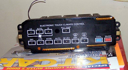
I am in the process of installing the automatic climate controll from an 1997-2003 grand prix into the fiero with a/c. I wired the 7 speed fan controller to have its power from the high speed relay when ign is on, and the 3 wires for speed control allowed a path for outside air temperature, as well as the signal to the 7 speed fan controller. I had to modify the housing to accept the fins as it was a larger opening than the resistor pack went through, and used a stainless steel backing for supporting the heatsink. I also had to slightly adjust the ac bracket to allow the motor controller to fit in place.
The 7 speeds is nice although without the car running it feels like speed 6 and 7 are the same, this could be due to it not at 13+ volts to allow the extra voltage. 1-6 you feel a chnge at each level. It is also nice to be able to controll recirc and ac independan of most modes ( no recirc with defrost only, but with blend.)
I believe the ac clutch signal will work with the ecm as it is a 12v signal, but I dont believe this will work with the radiator fan. I have a seperate switch that I will use to trigger the radiator fan (needs to be grounded) until I do an engine swap in the distant future
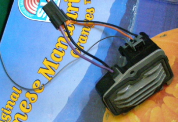
7 speed fan controller (found in front of the heater fan, under the dash in the grand prix, in front of the glovebox)
7 speed fan controller installed
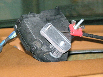
Heater temperature door control (found in the dash in the grand prix, on the drivers side of the glovebox) Homemade lever to still use oem cable.
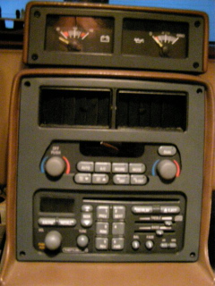
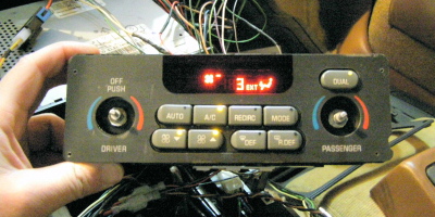
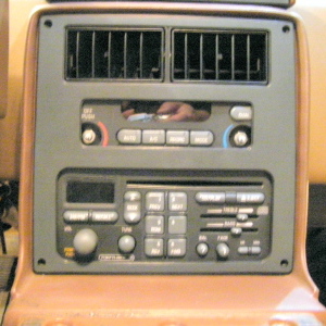
Display lit
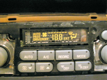
Display without cover
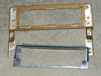
Oem climate mount that was removed (plastic could be riveted to the steel and put back to stock)
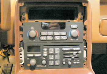
Testfit without wiring
Surround needs to be trimmed
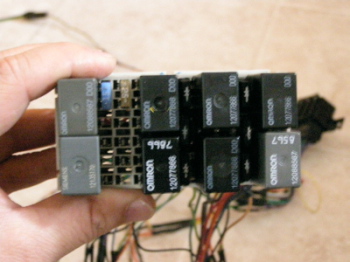
Relay block to switch grounds to plus for mode controller, 5 pin to sort which mode is priority in case of multiple modes commanded. Also there are diodes to protect controller and transistors are in one relay housing to protect mode motors. This is from the backside of the grand prix fuse box, there were three units and I used most of the wiring pigtails from all 3 to wire the relays. smaller solid state relays or some other method could be used.
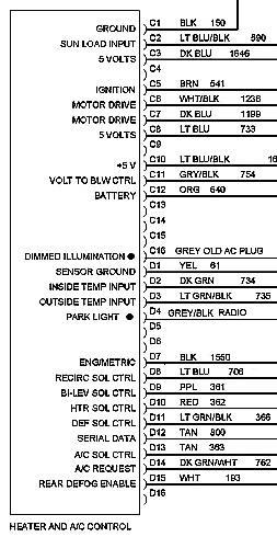
eddited to add pic of wiring diagram for back of climate control unit
rest of wiring diagram can be found here: enter 123456789 for library card #, select the link below it as "Library of Cincinnati", click submit, scroll down to AUTO REPAIR REFERENCE CENTER and pick your year and make. 97-03 grand prix gtp automatic climate wiring diagram
I did this to get rid of the resistors in the cowling, and to try out what I have read on the forum in other posts as impossible. I will not be making a kit, but a kit is made by Riceburner98 in the following post: https://www.fiero.nl/forum/Forum2/HTML/099236.html
I believe the cost would not be worth a kit for anyone using new oem parts thus I just wanted to let others know it can be done.
IP: Logged
06:52 PM
Riceburner98 Member
Posts: 2179 From: Natick, Ma, USA Registered: Apr 2002
Nice work! Before I started the whole aftermarket HVAC thing I had wanted to put either the (color) controls from the 92-95 3000GT or the ones from the donor Riviera into my Fiero.. I had it all planned out, but as usual never got the time then sold the car. The Buick one would have been easier, being GM like yours.. Your "attaching heater cable to servo motor" method is about the exact same way I do it. Works great. Now if you can get the dual zones working..........
Out of curiosity, do you know how wide that controller is? Still haven't found my radio cover plate, wondering if my controller would even fit within the walls of the console there.. I suppose I could just measure one of the Fiero radios since it appears to be the same size... As you have proven, all it takes is some determination to do this stuff. Nothing's impossible! People think I'm smart for being able to do this sort of thing, but in reality I'm just to dumb to know that I can't, and before I know it I'm in too deep to quit until I figure it out. LOL
IP: Logged
08:36 PM
Daniel Member
Posts: 282 From: Calgary, Alberta, Canada Registered: Jun 2003
Riceburner98 I was wondering what you use as the fan controller, if it was the stock resistors ar a unit like I am using above that allows more speed control (the above unit has 7 speeds) ?
The face of the hvac is 2 3/4" by 8" and almost the same depth as the radio, but after 1" from the face it tappers down significantly from the bottom, top and sides, allowing it to fit snugly in place. I also cut 1/8" from the bottom of the face so it drops down onto the radio, which also gives that little extra space. I cut the stock mounting plate from the sides of the gtp unit and drilledthe holes in the face where 4 through holes were that I had planned to use to bolt it to the faceplate. ( Currently in the testfit I am using foam to support the back up, and it does fit snug in place so mounting bolts maynot be necessary)
I have no plans to make make the dual zone functional, however I am keeping the button visable as it also serves the purpouse of self diagnosis when both driver and passanger buttons are pressed when the unit is turned off.
IP: Logged
10:34 PM
Mar 28th, 2009
Riceburner98 Member
Posts: 2179 From: Natick, Ma, USA Registered: Apr 2002
At first I made my own digital speed control like that, but it was too simple and got too hot. (similar to the dash light dimmer, just a switched transistor setup, but the fan draws a whole lot more current) I thought about using factory ones, but they're too much $$$ to buy more than a few. So I use the stock resistor packs, with a group of relays that replaces the fan switch. I'm hoping to get back to the multi-speed controller issue one of these days. It would have to be designed to drop in place of the resistor pack. As it is, there are 8 speed indicator "dots" around the fan icon on the screen, so for the Fiero I turn them on 2 at a time for the 4 speeds, for the Vintage Air I turn 3 on at a time since it only has 3 speeds. Though I don't remember any voltage dropping resistors on their motor, I think it has different windings for the different speeds. It's an SPAL blower motor, nice stuff. It would be very nice to have all 8 speeds working.
Yours looks just about stock with that radio in there. Are you going to trim the faceplate out all the way down to the radio, or try and leave a little "separator" bar between them? I've never had a whole lot of luck trimming that panel, I tried once and it made me mad. LOL
IP: Logged
09:25 AM
Daniel Member
Posts: 282 From: Calgary, Alberta, Canada Registered: Jun 2003
I may try leaving a bar between the radio and hvac controller,if this fails I could trim it out all together as the plastic face cover drops slightly over the face of the radio, but I want to test the cutting on a spare, which I don't have yet, I will try to get one locally. I think that i will probabaly use a scrollsaw. I was intially thinking of using aluminum surround and bolting the hvac to that, but the plastic should do just fine as it fits quite well without any mounting hardware on the hvac.
The only way I would buy the fan speed controller is at the junkyard, if at all possible, the price list is below from pick-n-pull. (need to keep an eye out for spares as my winter beater is an 98 gtp with this same controller, only with a green display) Radio- cd player ---------------$10 should have been 15 for cd, charged for a cassette version, half of wiring adapter included Digital hvac controller --------$20 needs backlight switch bulbs replaced, will get to eventually digital fan speed controller --$ 5 they called it a large relay- I was not going to correct them ----------- I would probabaly be willing to spend 15-20 for a spare locally Temperature door actuator --$ 5 they called it a large relay- I was not going to correct them on this either miscillaneous sensors -------$10 temp and sun load plus wiring cut out to use ----------- I am currently going to try out using intake air temperature sensor for inside cabin,
I believe the fan speed controller can be set up with more or less speeds as it is controlled by a varying voltage. I would like to get another controller to controll the fans in my engine bay based on temperature, with this controller you should be able to get the 8 speeds set up. but install was tight in the stock location.
Where is you'r inside cabin temp sensor? I will need to find a good place to set this up but testing this will not occur for a few more months.
Eddited for formatting pricelist
[This message has been edited by Daniel (edited 03-28-2009).]
IP: Logged
10:15 AM
Cajun Member
Posts: 1616 From: Youngsville, La., USA Registered: Dec 2003
Great write up........ I will be following this one closely.
I'm attempting the same thing, auto HVAC control. The difference is that I'm attempting to use '95 Riviera components as the foundation. This has proven to be difficult. At the intire system is based on the BCM (Body Control Module). At the time I was attempting only a instrument cluster modification. Needless to say the project grew beyond the instrument cluster mod. However, for the HVAC auto control one still needs the BCM, HVAC controller and fan power module. The neet part is if I ever get it working the fan control is infinite. I have already converted the HVAC controller from electro-pneumatic to all electric.
Anyway, as I indicated I will be following your build. I'm game to start over. Besides, at the local Pull-A-Part, parts are cheap.
Good luck........
IP: Logged
10:35 AM
Riceburner98 Member
Posts: 2179 From: Natick, Ma, USA Registered: Apr 2002
Where is you'r inside cabin temp sensor? I will need to find a good place to set this up but testing this will not occur for a few more months.
The controller I make doesn't actually have one... The "Auto" mode doesn't work, that was just to replicate the Diablo "Auto" button and screen icon. It turns on a relay if the person wants to control something else with it.. I *could* add an interior temp sensor, but the programming to make an actual Auto mode work would be a bit more than I want to get into. Well, to make it work "good" anyway. It would be simple to just try to get the temperature in the car to match the temperature on the screen, but in "real" ones as you've seen they have the sunlight sensor, plus sometimes other sensors, then they vary control of the different vent doors to try and equalize the temp. better. I believe the Diablo has a good 6 or 7 sensor inputs that it looks at. The sensors I use are serial based chips, so it's a matter of changing the address lines on the little sensor circuit board and plugging it in. I had pulled the temp. sensor from the Riviera (where I got my 3800) and it was a bare / uncovered resistive temp sensor, not unlike the intake temp sensor. It was in a tube that ended on the dash between the steering column and center console. I believe they sucked air across it to sample the interior. Not sure on the resistance though, you should be able to find that in the wiring info. Wouldn't be surprised if the intake sensor was the same one as the interior sensor. As for other places to put it... In the 3000GT it was in a little metal "pod" that was mounted to the headliner in the middle of the cabin.. But then if the car was sitting and the roof got hot in the sun.... Dunno how accurate that would be. Most GM ones I've seen have been mounted in the little tube in the dash.
Unfortunately the junkyards around here aren't pick-and-pull, I've got to drive to where I used to live about 45 mins away to find one. I do get my heater door servo motors from there though, and they usually charge $5 for them. They look at me funny when I come out with a dozen of them. I could pull the fan controllers at the same time, but not sure how many identical ones I could find. I need something "repeatable" in case I sell a couple hundred of these over time... As it is, I'm designing my own heater door servo that moves linearly rather than using the rotating arm. Will make it a bit more compact, and I bought the parts to make 200 of them. I figured if I couldn't find the servos in the junkyard anymore (though many GM cars use them), I could buy them new. At the time they were only about $40 from GMpartsdirect. But.... They've since redesigned them, and while they're the same shape and function similarly, they've made them cheaper to manufacture but bumped the price >$300. The newer ones that look the same also interface with the BCMs, so they're not as simple to control with just a variable resistor like the older ones.
Cajun - sounds like fun! My last 3800 swap morphed into something like that... I did a 3000GT dashboard and the 3800 motor, so I basically ripped out the Fiero wiring harness and combined Mitsubish and Buick Riviera harnesses, with the BCM thrown in there to control some stuff. It mostly worked in the end, but man that was a nightmare grown out of control! In the end the person that bought it wanted the stock Fiero harness back in, so I had to gut it and put it back to "GM" anyway. My initial thought was I would just take the (98) Riviera harness and install it into the Fiero like it was a smaller Riviera... Riiiight.... Good luck to you as well! Do you have any build pics elsewhere?
IP: Logged
11:04 AM
Daniel Member
Posts: 282 From: Calgary, Alberta, Canada Registered: Jun 2003
Fortunatley this does not need the bcm or computer ecm, However with the 3800 the controller would work better in auto mode as there is a delay in winter on when the fan comes up to speed, starting slow and increasing to fast as the coolant warms up. Without this I have read that the auto mode has a delault delay for waiting for the coolant to heat up, I am unsure about how long this delay is, but it can be overriden by taking it out of auto mode. The advantage of this controller is it controls vacume solenoids electrically, so I am able to trigger relays instead, but with diodes in to protect the controller, this allows the use of power to go through the transistors to protect the motors.
The recirc was simple, using a 5 pin relay switching from recirc to fresh air Power through transistor, switching between recirc and fresh air
The other modes was more complicated, requiring the order to prevent multiple modes commanded at the same time using 5 pin relays: Power through transistor input to: -Defrost otherwise bypass to: -Bi-level otherwise bypass to: -Vent otherwise bypass to: -Heater This allows the unit to operate, and believe the solenoids are working. The main deviation is that blend for heater and defrost is actually heat still as this unit has defrost, blend and heat, not just defrost and heat.
I believe I have read that in the auto mode fan speed is variable more than the 7 speeds, however in manual mode I have had no issues with the limitations of only 7 speeds in the grad prix in winter. I have read that the fan copntroller can fail but it seems that it would be better off in the fiero as the water in the housing would not pool on the unit as it would in the grand prix. The same fan controller is in the oldsmobile of the same era, and possibly some buicks but they must have auto controll.
I have read that pretty much all temperature sensors in the gm cars have the same resistors in them, even the temperature sensor for the dash, intake and engine coolant, so I will try using an intake air temp sensor for now as I was unable to find where the sensor is inside the grand prix when I pulled the parts.
IP: Logged
12:02 PM
Mar 30th, 2009
Daniel Member
Posts: 282 From: Calgary, Alberta, Canada Registered: Jun 2003
I've done quite a bit of work on the Fiero climate controls... Here's some info that should help with your project.
The connector to the climate control PC board has thirteen connections:
A - Illumination lamp supply B - Fan power (hot if OFF not pressed) C - Illumination lamp ground D - Hot to get DEFROST outlet E - Hot to get FRESH inlet F - Hot to get BILEV outlet G - A/C on signal to ECM H - GND for engine cooling fan relay J - Hot to get VENT outlet K - Engine cooling fan relay enable L - Hot for RECIRC inlet M - Hot for FLOOR outlet N - 12V power to the control unit (hot in run)
Note that there is no "I".
Also note that "A" is on the passenger side of the car with the unit installed in the dash.
The PTC's that Ogre mentioned are there to protect the motor and the control switches in the event that the motor gets jammed and tries to draw lots of current as a result of being stalled.
The system will function just fine without them but do realize that you are increasing risk of burning something out in the off chance that you stall a motor.
There are no transistors involved. There are no active components in the Fiero control head. The PTC's resistance is very non-linear with temperature and when they get too hot, the resistance shoots way up and cuts off the current. Shut the system off (read "turn off the key") and let the PTC cool off and it will "reset".
My recommendation would be to throw the vacuum controls as far as you can and either keep looking for an electrical donor or use a rotary switch from Radio Shack.
Hope the above is some help!!
-Bruce at FTF Engineering
IP: Logged
07:13 PM
PFF
System Bot
Apr 1st, 2009
Daniel Member
Posts: 282 From: Calgary, Alberta, Canada Registered: Jun 2003
Just adding an update, I have cut out the opening for the climate controll in the oem surround using a scroll saw, worked great just had to go slow to prevent the plastic from melting together. I will need to drill some mounting holes in the face to bolt the climate to, but I will try to get the wiring together before doing that.
IP: Logged
09:16 PM
Apr 2nd, 2009
americasfuture2k Member
Posts: 7131 From: Edmond, Oklahoma Registered: Jan 2006
I have a question regarding the heater door motors: from the schematics, they seem to be controlled basically through one wire, the rest is position feedback, supply, etc. Do you know how the position is controlled? A voltage, or a digital signal?
IP: Logged
05:45 PM
Apr 13th, 2009
Daniel Member
Posts: 282 From: Calgary, Alberta, Canada Registered: Jun 2003
Riceburner98 would know more about how the heater blower doors are activated, but I believe they are controlled through voltage, With this unit I dont need to know about how they work as all I did was wire it up to stock gtp spec, omitting the passangers side motor, and attaching the cable to the drivers side motor.
I dont know how it is controlled by the auto unit, but there are some cars that use these motors without the auto mode that could be more easily figured out, such as the buick regal that has i believe a resistor pad in the passangers door for controlling the passangers heat motor setting..
Pinout for heater door are below (auto 98 gtp unit): 5 +12v hot in run (brn) 6 motor drive (dk blu) 7 sensor ground (yel) 9 elec activator (lt blu) 10 +5 volts (lt blu/ blk)
Pinout from 95 regal manual a/c: one side of variable resistor gets 12v power. 7 (yel) other side of variable resistor resistor 8 (lt blu) run through variable resistor 10 +12v hot in run (brn)
For the mode controlls it is a ground signal that I used relays for to trigger the power through the transistors, and made it so only one mode in the fiero would be called for at a time by using 5 pin relays.
No real updates yet, I have wired the defrost mode to switch between celcius and farenheight temporarily. Hopefully in 2 weeks I will be able to replace the burnt out bulbs under the buttons and behind the hot/cold display to allow easier nightime use (not on road yet so no big rush). I have been wiring up a heads up display unit from the grand prix into the car, and won't be able to test the speedometer portion for a while as it is still parked, but it will be smaller than in the grand prix as no mirrors are used and the only modes I plan to use so far are speed, left and right signal, high beam and radio station setting (activated when station is changed or volume is adjusted), all but the speedometer have been tested above the dash, not mounted yet. The defrost button from the gtp is also being used to control the speedometer mode for switcking from kph to mph (I assume this would only allow limited time alternation as the defrost mode usually kicks out after 10 minutes first time, and 5 minutes afterwards.)
------------------ 1988 Fiero GT
IP: Logged
12:21 AM
Dennis LaGrua Member
Posts: 16187 From: Hillsborough, NJ U.S.A. Registered: May 2000
When I did the A/C system on my 87GT, I considered using the GTP A/C temp control module but the setup turned out to be quite involved. As you know the cabin temp sensor, outside air temp sensor, the refrigerent pressure sensor and the control module etc are all needed. The A/C system in my 87GT 3800 uses the GTP compressor and is wired to and under the control of the PCM via the refrigerent pressure sensor..However, it is triggered by the Fieros A/C request signal that is a simple +12V. There is no doubt that your system offers more flexibility and control and I am very interested in finding out how well it will work. Congratulations to you for trying such an aggressive project.
------------------ " THE BLACK PARALYZER" -87GT 3800SC Series III engine, 3.4" Pulley, N* TB, LS1 MAF, Flotech Exhaust Autolite 104's Custom CAI 4T65eHD w. custom axles, HP Tuners VCM Suite. "THE COLUSSUS" 87GT - ALL OUT 3.4L Turbocharged engine, Garrett Hybrid Turbo, MSD ign., modified TH125H " ON THE LOOSE WITHOUT THE JUICE "
IP: Logged
06:10 AM
Daniel Member
Posts: 282 From: Calgary, Alberta, Canada Registered: Jun 2003
The sensors that are required are: cabin temp sensor - currently using an intake air temp sensor from the engine as I could not easily find out where it is located. outside air temp sensor - wired through fan speed wires to front, as not all were needed and sun sensor are required - centre of dash at front, will mount after testing
Other devices required are: Main heater/ ac controller heater door actuator fan speed controller - nice not to worry about the resistors starting any debris on fire -still good to check annually relay block to switch input to motor doors
I am not planning on using the refrigerent pressure sensor (not required at all), I believe this is used by the ecm and the control module (ecm of engine, would use if I went with the 3800sc)
I believe the ecm gives coolant temperature information to the heater unit to allow a delay in fan speed turn on until the coolant is up to temperature in winter in auto mode, I believe it will operate without this. The heater display can also, in diagnostic mode, display current speed, as well as low speed and high speed fan turn on temperatures when connected to the ecm.
This would work with the Series II ecm, Which I believe you are running, I don't know if it would work with the series III ecm
IP: Logged
10:10 AM
RCR Member
Posts: 4454 From: Shelby Twp Mi Registered: Sep 2002
Very cool Daniel. I see a possible upgrade for my Grand Am dash in the future. Solves some of the issues in converting the GA control to run the Fiero box.
Just adding an update, I have cut out the opening for the climate controll in the oem surround using a scroll saw, worked great just had to go slow to prevent the plastic from melting together. I will need to drill some mounting holes in the face to bolt the climate to, but I will try to get the wiring together before doing that.
If it were me, which it is not of course, I would cut that hole rectangular to match the style of the radio cut out just to keep it stock looking. Nice work!
IP: Logged
08:13 PM
Apr 14th, 2009
Daniel Member
Posts: 282 From: Calgary, Alberta, Canada Registered: Jun 2003
great thread. a "+" for all the info, should help me with my project. I went more retro for mine....
John
Nice unit, although I find it odd that the fan controller is only auto, max or min, might actually be powered the right way so the relays are not required though.
quote
Originally posted by carbon:
If it were me, which it is not of course, I would cut that hole rectangular to match the style of the radio cut out just to keep it stock looking. Nice work!
Initially I had cut the surround just to fit, Although I am thinking about as you suggested, cutting the opening rectangular as I do believe it would fit in much better.
IP: Logged
12:01 AM
PFF
System Bot
Apr 27th, 2009
Daniel Member
Posts: 282 From: Calgary, Alberta, Canada Registered: Jun 2003
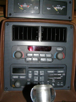
Bump for a short update, reshaped the cutout more rectangular, looks much better. Still need to figure out how to get A/C to work, currently have a seperate switch for that otherwise seems to work. (a/c trigger gives ~10v signal but not enough current to trigger relay, may need to try a solid state mini relay)
IP: Logged
06:56 PM
jscott1 Member
Posts: 21676 From: Houston, TX , USA Registered: Dec 2001
Bump for a short update, reshaped the cutout more rectangular, looks much better. Still need to figure out how to get A/C to work, currently have a seperate switch for that otherwise seems to work. (a/c trigger gives ~10v signal but not enough current to trigger relay, may need to try a solid state mini relay)
That looks great!
As for the 10V...what I would do is use the 10V knock it down enough to trigger a 5V relay and then use that to trigger the A/C
IP: Logged
07:11 PM
Daniel Member
Posts: 282 From: Calgary, Alberta, Canada Registered: Jun 2003
I just need to go and get the relay that will work, and build it into the housing of the mini 5 pin relay (did this for the transistors for the mode motor.) Will test it as is for a while first.
IP: Logged
08:14 PM
Apr 28th, 2009
Cajun Member
Posts: 1616 From: Youngsville, La., USA Registered: Dec 2003
Great writeup Daniel, I have been following your build from the start. The writeup has more or less inspired me to continue with my build of an electronic auto HVAC control system. The only difference I plan on using a '91 Riviera electronics as the foundation. As I have mentioned before, the system requires the use of a BCM (body control module). But, since I'm also attempting to utilize the digital instructment cluster from a '91 Riveria at the end it all goes hand in had. Hopefully.
Cajun
IP: Logged
06:42 AM
Daniel Member
Posts: 282 From: Calgary, Alberta, Canada Registered: Jun 2003
The functions that I am currently using from the HUD unit are: - speedometer - jacked off the lead to the power steering that was never installed from factory. - left and right signal lights - taped of the bulb socket - high beam - taped of the bulb socket - and radio setting (displays when radio settings are modified/ volume is changed) used gtp radio no dimming, riged for full brightness, with dimming automatically from light sensor
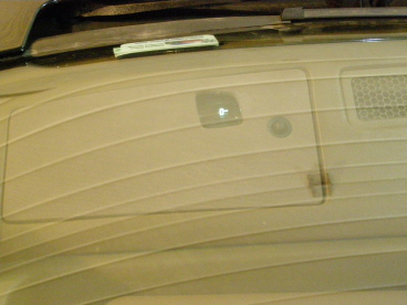
I used the 4th gen version, which the display is seperate, and cut out the circuitboard box from the main enclosure. I then soldered the sun sensor to leads and placed it in the stock sun sensor holder for the auto climate unit from the gtp. The display is bolted to a strip of aluminum that is friction fit between the dash and the steel mount, and held in with one bolt. The main problem is the display is much smaller (roughly half the height) however the advantage is it appears brighter as the light is not spread over as much of the windshield.
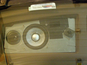
I had used a 5X7 component plate before, and used a plastic plate, now I used aluminum to mount the speakers closer to the side of the car as below, with the hole cut out for the hud to shine through, as well as a hole for the light sensor to stick through.
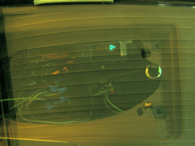
Here is the cover, with the cutouts for the hud, and the sun sensor
It is difficult to take the pictures, however here are two:
IP: Logged
08:26 AM
Apr 29th, 2009
Cajun Member
Posts: 1616 From: Youngsville, La., USA Registered: Dec 2003
For clarification, which components did you use from the donor car? I'm making a trip to the local Pull-A-Part in the next couple of days. I had planned on picking up the needed parts to see if this approach would be better than my current effort with the Riviera components. I still have not yet worked out all the bugs and since I have some spare time I would try your project.
Thanks, Mike
IP: Logged
06:41 AM
Daniel Member
Posts: 282 From: Calgary, Alberta, Canada Registered: Jun 2003
Remember to get a short wiring harness from the back of all units The components required are:
- Digital hvac controller - above radio
- Digital fan speed controller - in front of blower fan above passangers feet, remove cover and fan, remove front bolt and try wiggling it out, lossen rear 2 bolts if possible / necessary
-Temperature door actuator - passangers side is easiest to get to, remove glove box and it is to the left / near the centre of car
- Miscillaneous sensors - - outside temp, in front of radiator, passangers side - - inside temperature, unsure of location, (trying out an intake air temp sensor above passangers feet in the fiero for now) - - sun sensor, centre of dash by defroster , looks like the one in above post about the hud unit, a dome
- Miscellaneous wires - - lots of relays and diodes for the relay block - - relay block is the rear plugs for the relay block on passangers side, was 3 only enogh wires for the one, and I filled in the centre hole with one of the other relay blocks to fill it up.
IP: Logged
08:28 AM
May 8th, 2009
Cajun Member
Posts: 1616 From: Youngsville, La., USA Registered: Dec 2003
Tested a week ago, all seems to work that I set up. I still need to get the A/C to operate with the signal from the controller, I went to an electronics store near by and they were clueless on there products (solid state relays need some sort of wiring diagram). It seems the intake air temp sensor will work as the cabin temp sensor, currently held in place above the passanger footwell under the map pocket as a friction fit with a piece of foam. Hopefully in the next month I will figure out the a/c, for now I have a seperate switch for a/c and rad fan that seem to work fine.
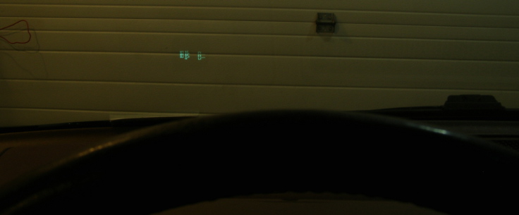
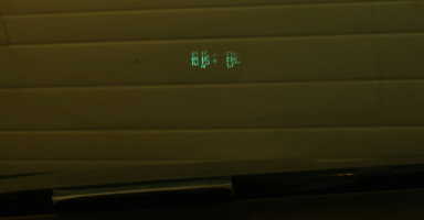
The HUD was also first tested and it is a nice feature, could have been higher on the windshield but not to bad (too high and it would be a distraction). It is small to read compared to the grand prix, a compromise between brightness and size. The radio settings are almost too small but still easy to read. It would be nice to set up the radio controls on the steering wheel so it would be easier to change stations and adjust the volume, maybe a future project.
IP: Logged
08:23 AM
PFF
System Bot
Cajun Member
Posts: 1616 From: Youngsville, La., USA Registered: Dec 2003
Again I want to thank you for your work, assistance and sharing of information. Needless to say it have been extremely helpful. Currently my build is on hold as I'm currently overseas. I have been communicating with another PFF member who is also currently involved with a similar build.
Thanks for sharing the information concerning the HUD display information.
Although I'm not physically working on the project I am attempting to work out some of the connection and wiring issues. I continue to work on the Riviera & Grand Prix systems. Which of the two I resolve the issues will the one that gets installed. I am however, favoring the Grand Prix build as the display is typical Pontiac red. I tend to like the effect at night.
Good luck on you build. If I have any break throughs I will definitely share.
Mike
IP: Logged
06:27 PM
May 22nd, 2009
Cajun Member
Posts: 1616 From: Youngsville, La., USA Registered: Dec 2003
Referencing the Fiero AC control head unit, does anyone know the specs for the two (2) thermistors?
I'm in the process of following Daniel and do a similar build. However, I want to ensure I protect the actuators (motors) in the existing HVAC box. I do not want to disassemble my existing AC control head unit to salvage the thermistors but rather install new but of equal value.
Thanks,
Mike
IP: Logged
06:23 AM
Daniel Member
Posts: 282 From: Calgary, Alberta, Canada Registered: Jun 2003
I don't know if I caught the engine application. Is this install being done with a 3800SC engine and PCM. I believe that you must have PCM control of the A/C in order to get the controller to do what you want it to do. .
------------------ " THE BLACK PARALYZER" -87GT 3800SC Series III engine, 3.4" Pulley, N* TB, LS1 MAF, Flotech Exhaust Autolite 104's Custom CAI 4T65eHD w. custom axles, HP Tuners VCM Suite. "THE COLUSSUS" 87GT - ALL OUT 3.4L Turbocharged engine, Garrett Hybrid Turbo, MSD ign., modified TH125H " ON THE LOOSE WITHOUT THE JUICE "
IP: Logged
08:51 AM
Cajun Member
Posts: 1616 From: Youngsville, La., USA Registered: Dec 2003
That is the beauty of this conversion, no BCM or PCM required. The new HVAC control unit is from a Pontiac so the display matches the Fiero RED glow. Once I return to the states I plan on posting what I have done to make this happen. Credit goes to Daniel.
Mike
IP: Logged
08:57 AM
Daniel Member
Posts: 282 From: Calgary, Alberta, Canada Registered: Jun 2003
With the 3800 the climate controll would be slightly more usefull as in the gtp it knows the coolant temperature from the engine as well as the speed of the vehicle. The a/c out signal I will set up to operate the a/c cluth as well as the radiator fan. Currently this is being installes on a stock 2.8 fiero.
IP: Logged
05:22 PM
May 26th, 2009
Cajun Member
Posts: 1616 From: Youngsville, La., USA Registered: Dec 2003
In your installed you provided a photo of the fan controller installed but provided no additional details. Do you have any other photos of the controller install what you can share? Do you have any tips or cautions you can share about the fan controller install?
Thanks
Mike
IP: Logged
02:58 AM
Daniel Member
Posts: 282 From: Calgary, Alberta, Canada Registered: Jun 2003
I will try to get some more pictures tonight of the fan controller mount.
- I did modify the ac cylinders bracket to give a little extra clearance (required). - I set up the bolt so it would not protrude as far back from the strap. - I highly recommend using a thin sheet of metal to help support where you mount the fan controller ~1/16" thick, - - I then used this metal plate as my guide for dremeling out the plastic around the mount of the resistor pack,
Wiring: - I used the high speed relay for powering the fan controller with ighition, using the trigger as an ignition from in the cabin. - For the speed controll I used one of the fan speed wires as the jumper to go from the climate unit to the fan controller. - The other two wired for fan speed were used as the jumpers for the outside temp sensor, and wires routed through the wiring harness bundle to the drivers side, and through the harness to the headlights. The sensor is just to the centre of the drivers edge of the rad opening bolted to the metal.
IP: Logged
08:17 AM
Cajun Member
Posts: 1616 From: Youngsville, La., USA Registered: Dec 2003
Thanks Daniel for getting back and responding to my questions.
I sent you an email to the email address you had posted in you Members List information. Basically, I was questioning if I could forward to you may work, wiring diagrams, etc. For your review to see if I have any fatal flaws in what I'm planning in the way of the install. There are some slight differences between your work, I believe your components were from a '97 while mine are from a 2000. At my currently location I cannot post photos or other documents.
Once I'm back home I plan on posting the install photos and all documentation, including wiring diagrams.


 Before I started the whole aftermarket HVAC thing I had wanted to put either the (color) controls from the 92-95 3000GT or the ones from the donor Riviera into my Fiero.. I had it all planned out, but as usual never got the time then sold the car. The Buick one would have been easier, being GM like yours.. Your "attaching heater cable to servo motor" method is about the exact same way I do it. Works great. Now if you can get the dual zones working..........