Blooze Own: An F355 Six Speed N* Build Thread (Page 45/126)
Bloozberry SEP 29, 08:00 PM
Ahhhh yes... the Honey-Do List... every married guy has one longer than his arm.

Speaking of lists, I have a little more progress to report on Blooze-Do List: I finally managed to complete the three-view of the front lower control arm drawing. What a bear this thing is. It has such a convoluted shape on the underside that around Hour 15 of trying to draw it, I realized that for my simple static analysis, I only really need to have a stick drawing with the essential dimensions on it. But then, how interesting would that be? So 20 hours of drafting later, here's the latest in the series of suspension drawings (I wouldn't try to make a set from scratch using my drawings ). The knuckle is next.

Three-view:


Top View zoomed in:


Rear View zoomed in:


Side View zoomed in:

[This message has been edited by Bloozberry (edited 09-29-2011).]

Bloozberry OCT 08, 10:09 PM
Only a few more pieces to go and this stock suspension stuff should be over and done with. That will allow me to get on with designing the new rear cradle and hopefully prove the changes will result in improved geometry... at least on paper. But then that's all I'll need to do to satisfy the looming legislation here in Canada which would place strict certification processes on modified suspensions.

Enough of that. I've been slaving away in my spare time getting the front knuckle drawn up. It was a little challenging since there are some interesting angles which complicate getting accurate measurements, but after double and triple checking things using alternate measuring techniques, I'm confident it's very very close. What made matters worse is that I wasn't able to separate the bearing assembly from the knuckle as I did for the rears. I would have had to take the assembly to a shop with a hydraulic press to get them apart. If I had planned to actually use these knuckles and bearings, I would have done that, but since they're only being used for camparison's sake I drew the parts stuck together, like they are. Here's the three-view:


One interesting issue I found is that the P22 parts book lists the RH and LH knuckle part numbers as 10046484 and 10046483 respectively. However cast right into the RH knuckle I used is part number 10048486 with additional castings GM and 84. Are there earlier and later versions of the 88 knuckles?

The next hurdle will be to try to accurately measure the dimensions of the upper and lower ball joints. The center of the pivot point won't be easy to determine with any great accuracy. I tried Googling ball joint dimensions, and schematics, and specifications, and drawings... nothing came up. I did find an obscure thread somewhere where a guy was trying to do the same thing as me for his Honda. He was told by Moog and several other manufacturers that they didn't release that information since it was proprietary. As if we're all going to start making our own backyard ball joints! Hopefully I'll be able to figure out a way without resorting to cutting one of each up. Anyone have any leads for the data or ideas on how to measure it?

(Edited to update drawing)

[This message has been edited by Bloozberry (edited 11-16-2011).]

Zac88GT OCT 09, 03:25 PM
When I modeled the miata ball joints I'm using for my locost i moved the joint all the way to one side and drew a line down the center of the joint, then moved it to the other side and did the same. I then used the intersection point as the center of rotation. I feel it worked reasonably well but without cutting it apart there's not much else you can do.

[This message has been edited by Zac88GT (edited 10-09-2011).]

Gokart Mozart OCT 09, 10:27 PM
http://kitcar.automotive.co...steer-kit/index.html

http://www.locostusa.com/fo...?f=5&t=1292&start=60

pirate4x4.com/tech/billavista/PDFs/Moog_Ball_joint_spec_chart.pdf

http://www.meisners.net/fiero/Home%20Alignment.htm

[This message has been edited by Gokart Mozart (edited 10-09-2011).]

Bloozberry OCT 10, 09:05 AM
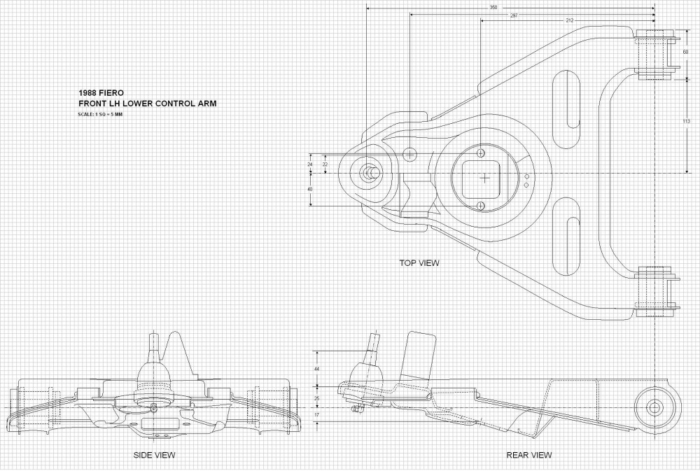
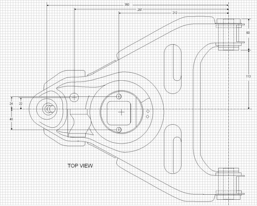
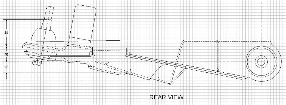
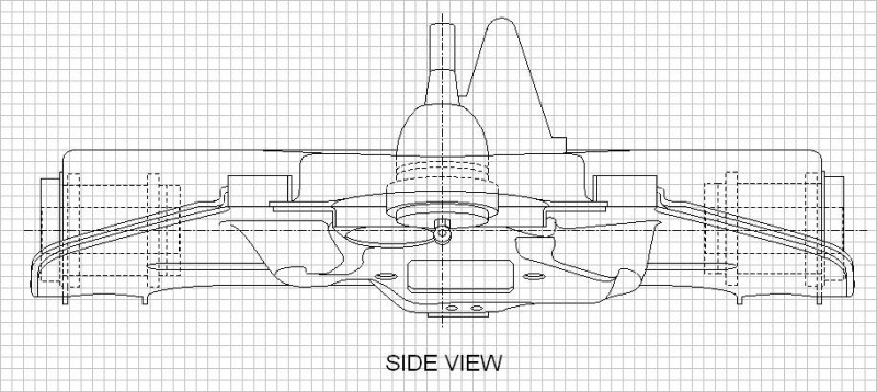
Thanks Zac and Gokart. For Zac, I used your suggestion and it seemed to have worked relatively well. The upper is now done, I just have to work on the lower one now.

For Gokart Mozart: I looked at the four links you provided but only found the third link helpful. On page 18 there was a cross section schematic of an upper and lower ball joint which helped me to visualize the guts a bit better. Not exactly sure why you posted the other links though.
Gokart Mozart OCT 10, 11:57 AM
they had dimensions, thought they might be helpful
5150fauxarri OCT 12, 08:15 PM
Hey Booz. I dont know if you would be interested or even if you are allready fallowing the build. But under the General Fiero Chat, there is the topic of "My Mera Style 308 Project". The only reason I bring it up is he makes some pretty nice 355 taillights. I've noticed you have the same crappy outer lenses I have and just thought you might be interested. Currently he has posted pictures of the f355 taillights but hasnt put a price on them but Im sure I will be a customer.
Bloozberry OCT 12, 08:36 PM
Thanks for the tip 5150fauxarri. But I'm one step ahead of you! A couple months ago I bought a set of new OEM tail lights from Don Ostergard here on PFF who was getting out of an F355 project car.
Bloozberry OCT 14, 05:02 PM
This week I worked on the ball joints and the front upper control arm mount. Trying to determine the exact center of the ball joint pivot points was a little daunting at first, but I came up with a measurement method that estimated the location within the precision needed for this analysis. I removed the boots and cleaned the grease from the exposed part of the ball, then swung the stud all the way to one extreme of the permissible movement and measured the lateral and vertical displacement of two fixed points along the centerline of the stud. Then I swung the stud to the other extreme and did the same. These four points described two converging lines that intersected at a point where the pivot center should be. I repeated the measurements several times for each ball joint and then used a bubble level protractor as a back up method, and not surprisingly came up with a very round measurement for both ball joints; 25 mm (or 1 inch) below the lower edge of the where the taper stops on the studs. It makes sense too that a ball joint manufacturer would use common dimensions for these sorts of things rather than some odd number... at least that's what I tell myself trying to rationalize my results!

Here's the upper ball joint. One interesting note is that both ball joints insert into their respective tapered holes in the knuckle right up to the depth where the taper on the stud ends:


And here's the lower ball joint. You'll notice that I didn't include as many measurements simply because not all of them are important, and outside dimensions may differ between manufacturers:


Finally, a simple little drawing of the upper control arm mount.


One last drawing to do before I can start sticking all these pieces together: the steering tie rod.

(Edited to update both ball joint drawings)

[This message has been edited by Bloozberry (edited 11-16-2011).]

5150fauxarri OCT 14, 11:32 PM
Your work is so nice I would happily take the peices you throw away thats not good enough for you!