Pennock's Fiero Forum
  Technical Discussion & Questions
  CNC help

Post New Topic  Post A Reply
Email This Page to Someone! | Printable Version


next newest topic | next oldest topic
CNC help by sspeedstreet
Started on: 04-16-2021 02:38 PM
Replies: 4 (284 views)
Last post by: Coolkoolpyle on 04-17-2021 02:24 PM
sspeedstreet
Member
Posts: 2306
From: Santa Maria, CA
Registered: Dec 2002


Feedback score:    (18)
Leave feedback


Total ratings: 53
Rate this member

Report this Post04-16-2021 02:38 PM Click Here to See the Profile for sspeedstreetSend a Private Message to sspeedstreetEdit/Delete MessageReply w/QuoteDirect Link to This Post
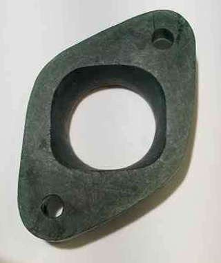
I'm trying to get some insight from people who do CNC machining. I'm working on headers for my 1992 3.4DOHC engine (in a 1988 GT). For the flanges I'm making individual pieces to blend the "D" port shape over to the correct round diameter. I have the pieces to the correct thickness and the profiles (outer shape, pipe ID and the bolt holes water jet cut. I'm now faced with cutting the blend profile by hand (ugh!) or maybe having it done by CNC.

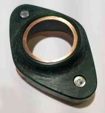
My original thought was having them lost-wax cast. To that end I hand carved a File-Wax model (below).

Here's my question: Is it possible to digitize this inner shape and then use the file to machine the parts? The material is 321 stainless steel.


Thanks
IP: Logged
PFF
System Bot
zkhennings
Member
Posts: 1922
From: Massachusetts, USA
Registered: Oct 2010


Feedback score: (3)
Leave feedback

Rate this member

Report this Post04-16-2021 05:03 PM Click Here to See the Profile for zkhenningsSend a Private Message to zkhenningsEdit/Delete MessageReply w/QuoteDirect Link to This Post
It is very easy to make a lofted form from two sketched profiles on different planes. Do you have a way to measure the D shaped side of things to put it into a CAD sketch? The circular side is obviously simple to create in CAD. If you have any photoshop experience I think you could sketch the profile by hand, scan it, convert it to a layer containing just the sketch line itself, import that into CAD, make a sketch in CAD that follows the form, and then constrain it with a few major dimensions.
IP: Logged
sspeedstreet
Member
Posts: 2306
From: Santa Maria, CA
Registered: Dec 2002


Feedback score:    (18)
Leave feedback


Total ratings: 53
Rate this member

Report this Post04-16-2021 07:56 PM Click Here to See the Profile for sspeedstreetSend a Private Message to sspeedstreetEdit/Delete MessageReply w/QuoteDirect Link to This Post
Is this a place where a digitizing probe could be used?
IP: Logged
Coolkoolpyle
Member
Posts: 55
From: IA
Registered: Sep 2020


Feedback score: N/A
Leave feedback

Rate this member

Report this Post04-17-2021 02:20 PM Click Here to See the Profile for CoolkoolpyleSend a Private Message to CoolkoolpyleEdit/Delete MessageReply w/QuoteDirect Link to This Post
A probe is a bit over kill

A simple old school rubbing with a crayon and paper could be easily scanned in and turned into a template on auto cad.
IP: Logged
Coolkoolpyle
Member
Posts: 55
From: IA
Registered: Sep 2020


Feedback score: N/A
Leave feedback

Rate this member

Report this Post04-17-2021 02:24 PM Click Here to See the Profile for CoolkoolpyleSend a Private Message to CoolkoolpyleEdit/Delete MessageReply w/QuoteDirect Link to This Post

Coolkoolpyle

55 posts
Member since Sep 2020
A rubbing of all three ports as they are on the head would also give a exact distance and bolt location allowing you to create a flange connecting all three ports giving a substantial increase in support and rigidity to the design and discourage cracking at welds.

A one piece design would be very superior to individual flanges for each port.
IP: Logged

next newest topic | next oldest topic

All times are ET (US)

Post New Topic  Post A Reply
Hop to:

Contact Us | Back To Main Page

Advertizing on PFF | Fiero Parts Vendors
PFF Merchandise | Fiero Gallery | Ogre's Cave
Real-Time Chat | Fiero Related Auctions on eBay


Copyright (c) 1999, C. Pennock