|
| LS4 / F40 swap - fieroguru (Page 2/209) |

|
mera7
|
DEC 13, 05:09 PM
|
|
|
so the ls4 has the same bolt pattern as a fiero getrag?
|
|
|
|
fieroguru
|
DEC 13, 05:51 PM
|
|
| quote | Originally posted by mera7:
so the ls4 has the same bolt pattern as a fiero getrag? |
|
Yes:
From my perspective, there are benefits and drawbacks to the LS4...
Benefits:
1: It comes with the FWD metric pattern and will physically bolt to a fiero transmission w/o any need for an adapter plate (but you have the starter issue).
2: Since it does not come with the RWD/SBC patten, they can be had dirt cheap compared to the other aluminum block LS(x) engines (try finding an 18K mile LS1/LS2/LS3 complete with tranny for $1000).
3: They come with the 243 heads which are the best stock cathedral port heads.
4: The accessory drive is more compact... but far from perfect.
5: It is a DoD engine and the 2007+ engines with the 58 tooth cranks can be retrofitted with VVT cam phasers.
Downsides:
1: Stepchild of the LS(x) family with minimal aftermarket support.
2: No starter provision on the engine.
3: No factory manual transmission application.
4: DoD limits camshaft choices and complicates the intake swap options (and without a better intake, a cam upgrade is pretty much a waste)
5: Accessory drive is overly complicated and makes alternator placement an issue.
6: It is only 5.3L
7: Engine is ugly w/o the engine cover.
|
|
|
|
fieroguru
|
DEC 13, 06:16 PM
|
|
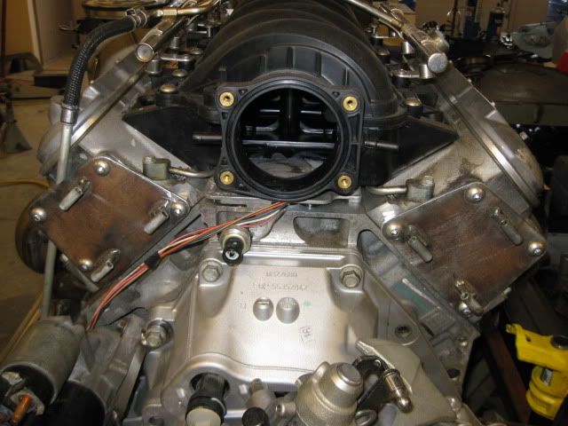
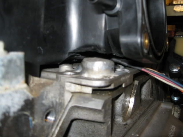
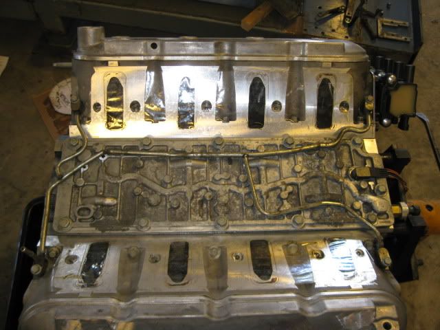
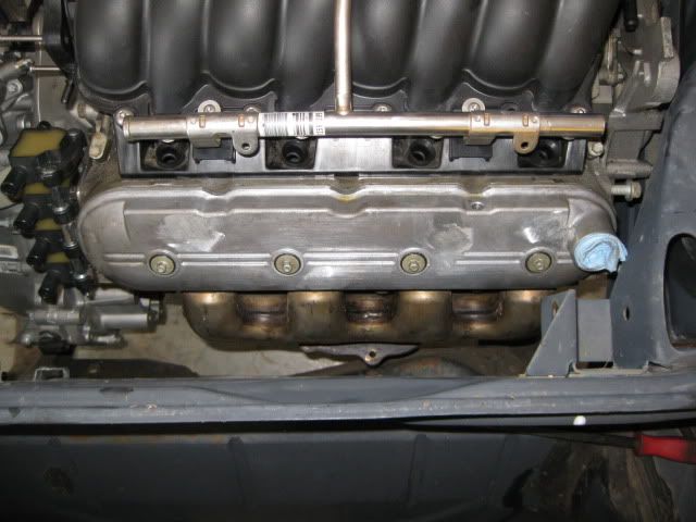
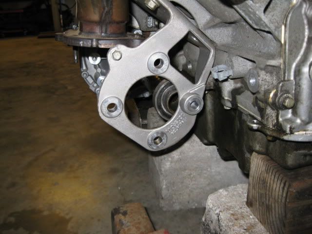
This swap needs to look good without any engine covers… so first thing that needs to go is the LS4 intake… it is just ugly (and a restriction). Now while the LS2 intake isn’t as good as the LS6 one, it has very clean lines for use without any covers.
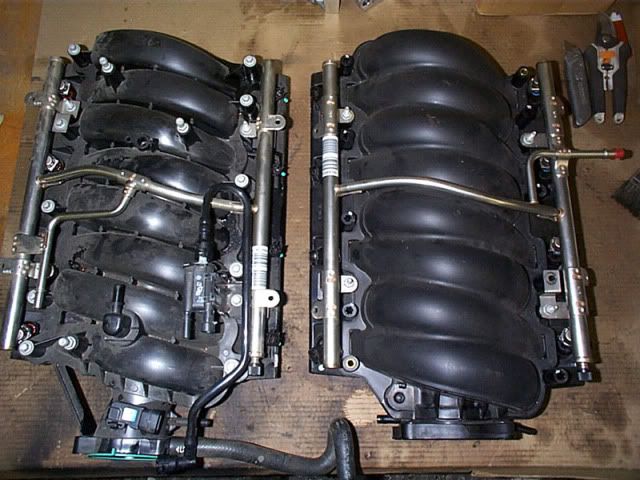
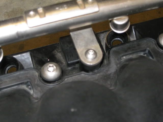
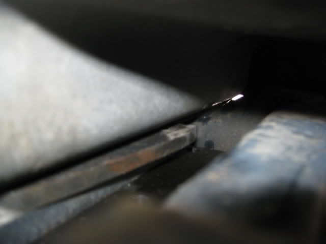
The problem is the LS2 intake will not fit the stock LS4 DoD valley cover without major clearance work (it fits just fine with some minor work when used with non-DoD valley covers - Archie’s swaps do this all the time). Even with the OPSU boss cut down about 1/2" in this picture, you can see the valley cover needs to come down another 3/8" to be able to fit... this is going to take some work.
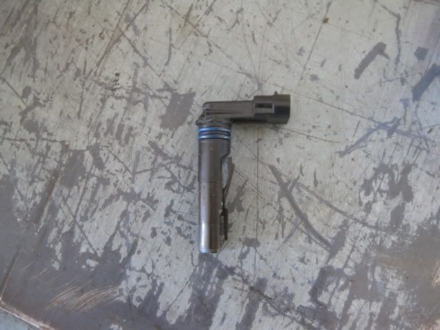
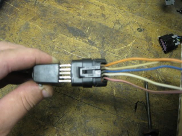
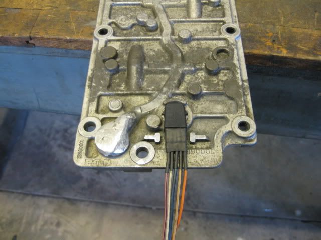
First thing under the knife was the connector. Right behind the flange for the connector, I gently cut through the plastic and eventually was able to pry the end off exposing the 5 terminals:
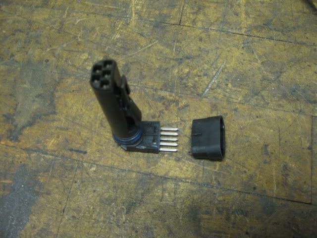
Call me finicky... but I wanted to know the OEM wire colors for this connection so the new wires (recycled from other GM harnesses) can match.
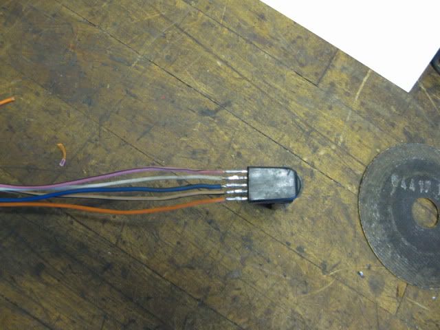
New wires (about 24" in length - way too long) soldered to the appropriate terminals:
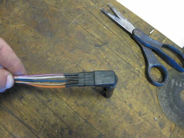
Heat shrink x2:

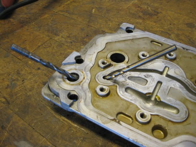
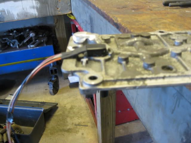
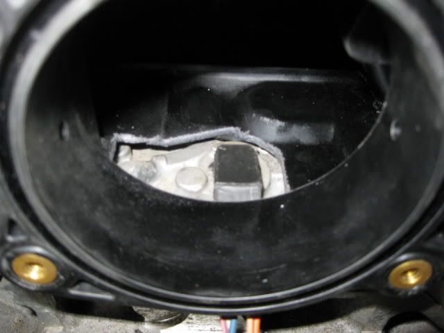
Now back to the OPSU - it will be relocated entirely. I had already cut it down about 1/2" and cut it down another 3/8" to expose the oil passage while still leaving material to drill a new oil passage.

New oil passage:
Then the top side of the OPSU boss was welded up to close up the passages. Here is a finished pic of the welded OPSU and the modified connector:
Sadly, the LS2 intake still isn't going to accept installation without modifying the intake.
Lower ribs flattened and the area of the connector and OPSU was cut open (this also give me room for the vent upgrade):
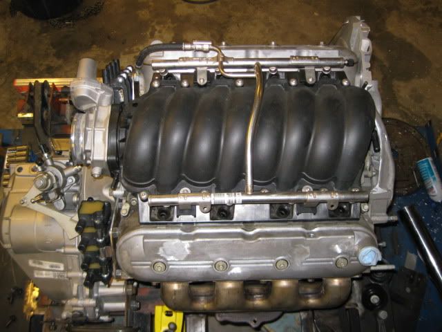
But now it can be installed w/o interference:
Patch panel fabricated to seal the hole:
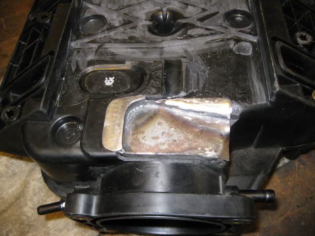
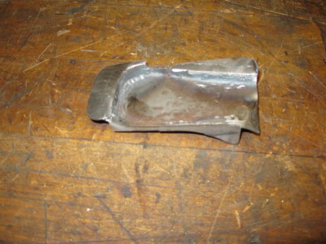
This patch panel was glued in place inside and out.
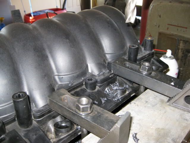
Just because I thought they would look better, I cut the intake manifold bold bosses down about 1”
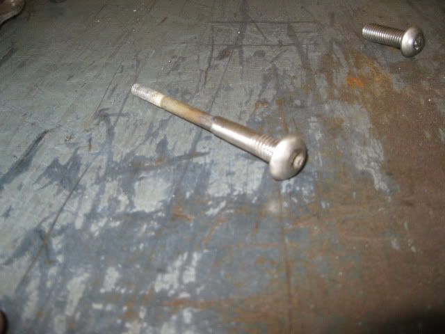
I have a sickness for stainless steel button heads and even at this shorter length, they just do not exist in the proper length/thread... so I made some using some other metric stainless steel button heads. Drilled the center, cut the OEM bolts the proper length, pressed them into the bottom of the button heads, weld then together, grind off the excess...
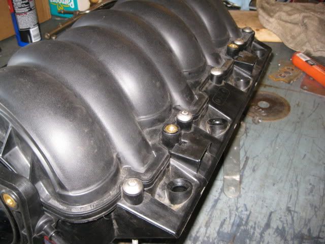
Even have button heads for the fuel rail and throttle body:
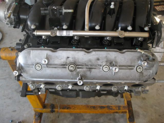
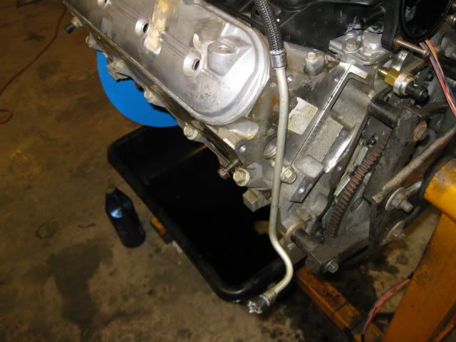
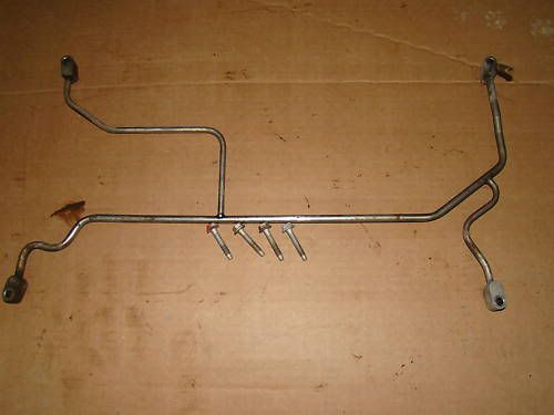
The last intake manifold modification was to bend the stock LS2 fuel rail so the fuel line will not cross over the valve cover (like the stock LS4) and then bent the original LS4 fuel line to go down the end of the head and exit down low away from the exhaust.
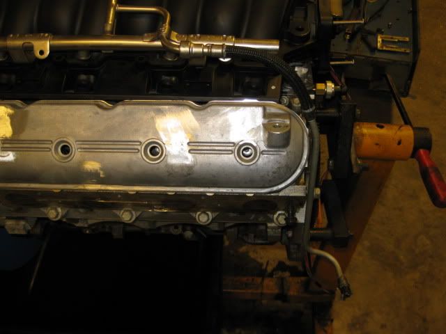
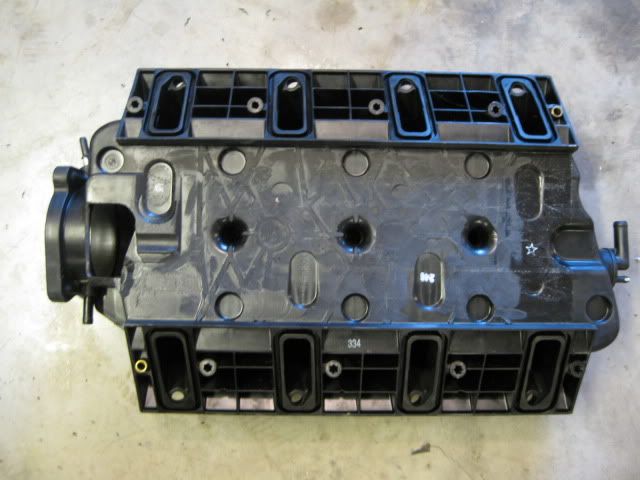
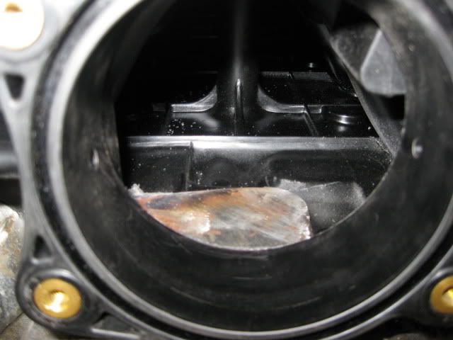
In this picture you can see where the OPSU was relocated - drilled/tapped the oil passage below the valley cover:
One last upgrade while the intake is off…
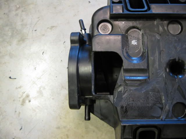
I plan to wail on this engine once installed and it might see some NO2 at some point, so I went ahead and installed the 4 corner vent setup from a 6.0L truck just to ensure cylinders 7&8 have the best chance for equal cooling.
It took some slight bending of the lines to route them around all the raised bosses and oil passages and I bent the exit tube to be vertical so it clears the intake. 2 bolt bosses for the DoD stuff under the cover needed cut down, but not far enough to touch the bolts. Some RTV should seal them back up. The bottom corner of the LS2 intake (the triangle part that rests between the heads and the valled cover) needed about 1/2" trimmed from it at the corner to clear the tube in the upper right hand corner of the picture. But now it fits!
 [This message has been edited by fieroguru (edited 12-13-2010).]
|
|
|
|
fieroguru
|
DEC 13, 06:38 PM
|
|
|
|
|
mera7
|
DEC 13, 06:41 PM
|
|
|
once again... very nice work guru.
|
|
|
|
fieroguru
|
DEC 13, 06:55 PM
|
|
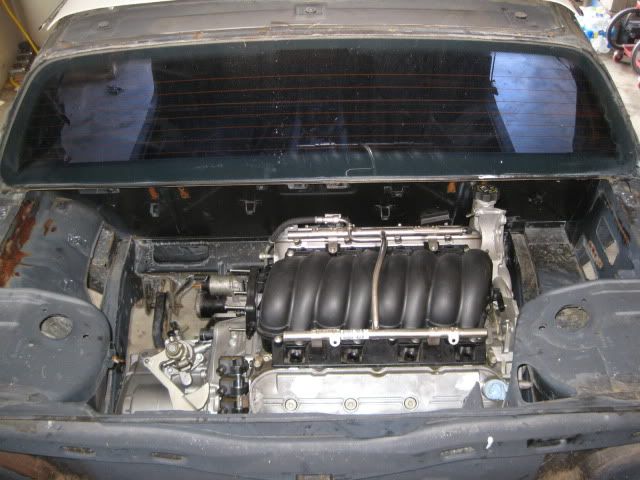
The LS4/F40 combo is somewhat misleading in how much room most would think there would be to install. Truth of the matter is the LS4/F40 combo is a very tight fit with the factory water pump and an unmodified 88 cradle. My mockup chassis has bolt in hinge boxes, so I left them out for this test fit. That is the only deviation from a 100% stock 88 engine bay (other than the battery tray). The elevation and engine placement in the pictures is dictated by clearance issues in several areas. Once these clearance issues are addressed the engine placement/elevation could be moved around a little more.
Overall engine bay view :
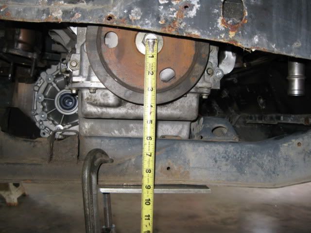
The crankshaft centerline is about 9 1/8" from the bottom of the 88 cradle (height was dictated by clearance issues, but with some modification it can go lower):
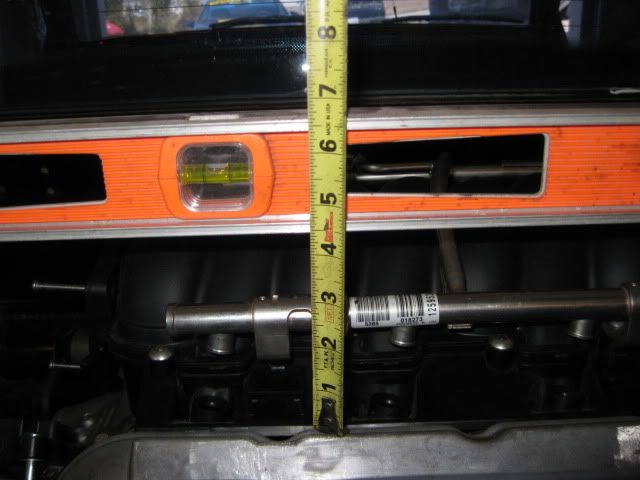
Another reference to elevation is this measurement from the flat top of the strut towers to top most portion of the valve cover:
On the engine side of things there are clearance issues with...
Oil fill with dog bone bracket:
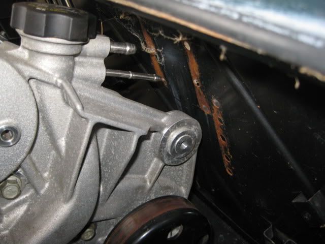
Water pump bolt with strut tower:

Idler bracket with strut tower and balancer to passenger frame rail:
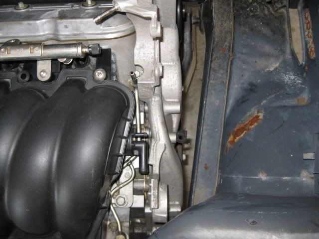
Coolant fill with hinge box and front idler with firewall:
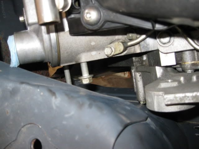
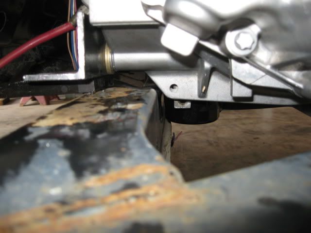
Oil pan and engine mount bracket on cradle (this and the tranny to frame rail dictated the engine elevation to clear everything):
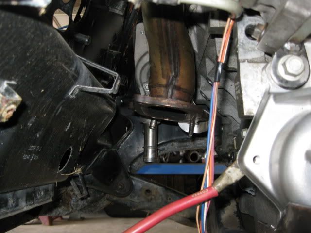
Oil filter to front cradle cross member:
Front exhaust manifold to the double firewall section:
Oil pan to bottom of cradle (about 1"):
Moving on to the transmission side of things:
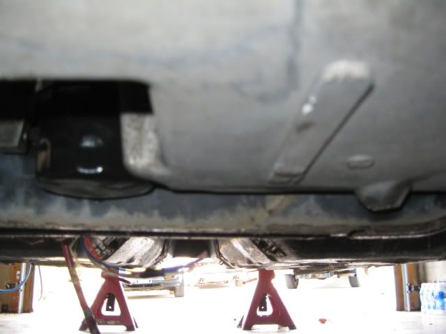
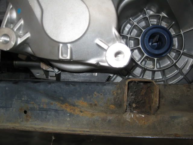
Tranny to driver side frame rail (it is touching):

Tranny to the cradle side rails (notice my shim to level the engine/tranny - this will be the elevation limiter before the bottom of the cradle):
Other important dimensions:
Valve cover to rear firewall = 2 3/16"
C/L crank to C/L of front cradle bolt = 15 5/8 (measured horizontal, not angular)
Bell housing face is offset 5 1/4" from the cradle centerline to the driver side
Here is a good comparison between the axle centerlines locations between the F40 and the 4T65. The elevation is pretty close, the F40's axle is close to 2" closer to the engine than the 4T65:
As you can see in the pictures where the engine is sitting is dictated front to back by the idler pulley to firewall & Oil filter to cradle in the front and idler pulley to strut tower clearance to the rear. Side to side placement is tranny to DS frame rail on the left and water pump bolt to the strut tower on the right. Elevation is dictated by the stock cradle engine mount to oil pan interference.
Moving the engine forward will gain more clearance side to side and to the rear of the engine. This is what all the LS4/4T65 swaps done to date have done by notching the cradle for the oil filter and relocating the front idler back an inch or two. Removal of the stock engine mount on the cradle will allow the engine to lower about 1/2" and to go any lower would require some work to the tranny case or cradle side rail.
|
|
|
|
qwikgta
|
DEC 13, 07:18 PM
|
|
Great looking build. Next spring/summer I plan to do some "cleaning" of my LS3 too.
I love your clean install.
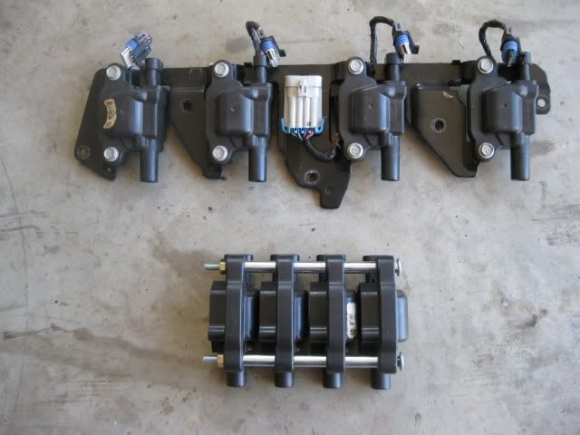
The coil reloc kit i'll be using is here. http://www.automotivedesign...ducts/coil_pack.html
I have to go with this, because I don't have access to welding equipment.
Keep it up, this is my new favorite thread.
Rob
|
|

|
mera7
|
DEC 14, 03:34 AM
|
|
|
my favorite thread as well.
|
|
|
|
fieroguru
|
DEC 14, 08:31 AM
|
|
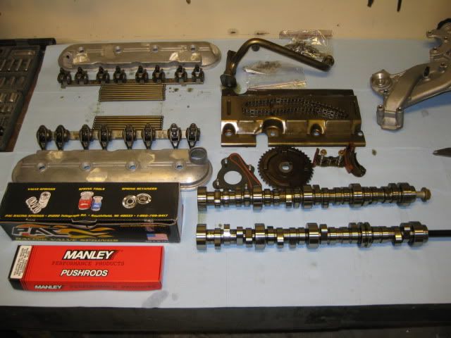
When it came to the camshaft, there were a few options I considered:
1: Ditch all the DoD stuff and run any LS(x) cam I wanted… lots of work and cost to replace the lifters, oil pump, valley cover, etc, and the heads have to come off… which always leads to more upgrades. Downside/Upside is you lose DoD… but have an near endless selection of camshafts to pick from.
2: Stock LS4 cam (193/193 .283/.283 @ 114lsa – Non DoD lobes) with 1.80 or 1.85 rockers – this is the least expensive and simplest approach, but gains would be minimal (10-20hp). Several LS4 guys have done this on LS1 tech.
3: Stock G8 cam (197/207 .278/.282 – non DoD lobes) with 1.80 or 1.85 rockers. Slightly more expensive than the using the stock cam and requires a camshaft swap, but provides more duration vs. stock LS4 and was a factory DoD camshaft. Probably would result in a slight improvement vs. the stock cam and rockers, bust still very mild.
4: Go with a much larger DoD compatible aftermarket camshaft… this is the route I took. This camshaft was designed for DoD and comes with the springs, pushrods, chain tensioner… only downside is they would not tell me the specs. The one guy on LS1 tech who installed this cam and said it was big (peak power in the 6800-7000 range), probably too big, but if he could still get his 3400 lb automatic beast moving with the cam. It has also been installed in some 5.3 full size trucks… so I figured it would be OK in a 2900 lb fiero with manual transmission and a stump pulling gear ratios. This cam was advertized to provide a 54 hp increase on the 6.0L… so for better or worse I went big.
Since they would not tell me the specs… I just HAD to find out what they were, so an 18” degree wheel was added to my tool collection.
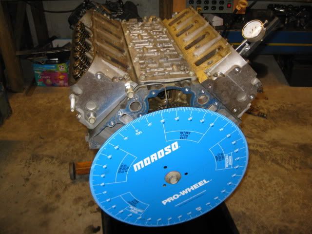
First order of business to degee the stock LS4 cam on cyl #1 (which is a DoD cylinder which might explain why my measurements are slightly different than the internet specs… I took a degree reading at .006, .050 and every .025 up to max lift up and down for intake and exhaust).
Stock LS4 camshaft specs: 197/197 .286/.286 @ 114LSA
Stock LS4 events @ .050 lobe lift:
IVO (BTDC): -18
IVC (ABDC): 35
EVO (BBDC): 31
EVC (ATDC): -14
I never confirmed the G8 stock specs… but here they are for comparison
Stock G8 DoD camshaft specs: 197/207 .278/.282
IVO (BTDC): -17
IVC (ABDC): 37
EVO (BBDC): 40
EVC (ATDC): -12
I did the same for my aftermarket camshaft and it was 224/231 .332/.338 @ 113 lsa but I also noticed it was really not what I was expecting. Here is an overlay of the two cams with the larger/wider lobes being the aftermarket one. As you can see everything was moved much later in the cycle.

So I spent quite a bit of time checking out other cams of the 224 to 230 duration, comparing where the valve events are for those camshafts and where mine were to figure out a better position in which to install the camshaft. A couple of the comparison cams are as follows:
MTI Stealth II 224/220 (everything at .050 lobe lift)
IVO (BTDC): -4
IVC (ABDC): 48
EVO (BBDC): 46
EVC (ATDC): -6
Comp Cams xer 224/230 (54-444-11 XER273HR)
IVO (BTDC): -1
IVC (ABDC): 45
EVO (BBDC): 50
EVC (ATDC): 0
After much thought and discussion with the other guy running this cam, I chose to install the came with the approximate valve events at .050” lobe lift:
IVO (BTDC): -3.5
IVC (ABDC): 47.5
EVO (BBDC): 46
EVC (ATDC): 5.5
This installed position places the new cam intake centerline right on top of the stock LS4's and pulls the IVO event back down to a more reasonable level for the 5.3 (it is still pretty high). This could be a major mistake, but only time will tell…
 [This message has been edited by fieroguru (edited 01-03-2011).]
|
|
|
|
Will
|
DEC 14, 05:16 PM
|
|
| quote | Originally posted by fieroguru:
4: Go with a much larger DoD compatible aftermarket camshaft… this is the route I took. This camshaft was designed for DoD and comes with the springs, pushrods, chain tensioner… only downside is they would not tell me the specs. |
|
Wow... I would NOT have bought a cam from an outfit that wouldn't give me at LEAST *BASIC* info on the duration, lift and lobe sep. The fact that they do that and expect people to buy it black box is INSANE. If any outfit told me that, I'd tell them their competitor is getting my money. Holy cow. The fact that people buy it black box and just install it (without degreeing it as you've done) is even more insane. Do all the cylinders degree the same? In your shoes I would be *highly* suspect of any quality issue with that cam, from consistency of grind from lobe to lobe to material to heat treatment/surface hardness to straightness. I wonder if the outfit even knows what specs they're selling. Are your prepared to lunch your engine if that cam wipes a lobe into your oil pan? I know it's a roller, but crappy material is still crappy material.
I hope for your sake it's actually made of steel and not some tin plated lead casting out of China. Is it at least magnetic?[This message has been edited by Will (edited 12-14-2010).]
|
|
|
|