
 
     |
| LS4 / F40 swap - fieroguru (Page 156/197) |

|
Will
|
JUN 03, 10:54 AM
|
|
| quote | Originally posted by fieroguru:
Turbo is back together with the heat shields. Cut the stainless steel studs to the proper length and used stainless nuts for all attachments. Also installed the stainless elbow for the oil feed (planning to run hard stainless lines for all oil and vacuum & boost signal lines.
|
|
FYI, Stainless bolts or studs with BRASS nuts and anti-seize works even better than stainless nuts, as the possibility of galling when removing a nut after many many heat cycles is significantly reduced.
|
|
|
|
fieroguru
|
JUN 06, 08:08 PM
|
|
The CNC Plasma table is in transit! The expansion kit, laptop stand and plasma cutter are already here, but haven't pulled them out of the boxes yet.
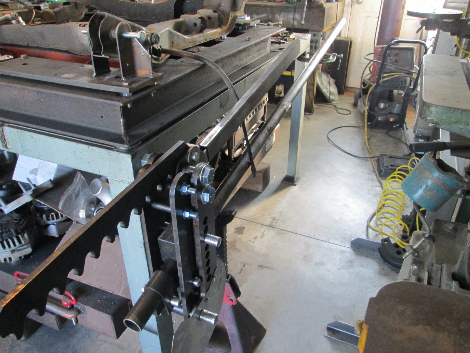
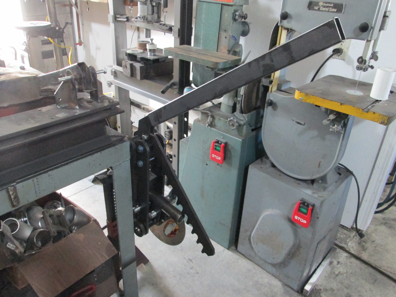
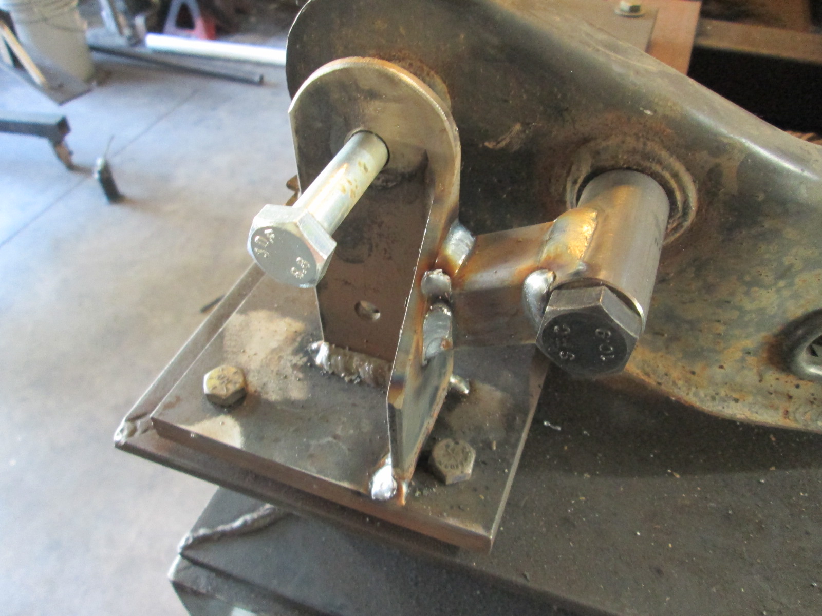
My new (heavier) tubing bender arrived this week, so I spent some time up-sizing several of the bolts and will also upgrade the pins. Mounting it is a little bit of a pain as I didn't buy the stand (because I don't have room to put it out in the open floor) and I don't like the idea of using my vice (and it would lack space for the tube). My metal work table is quite sturdy and normally have 500+ lbs of engine/transmission/cradle fixture on it, so I decided to mount the bender to one of the legs. I wanted to pull down vs. pull up and wanted to keep it as much out of the way as I could. This is what I came up with for now:
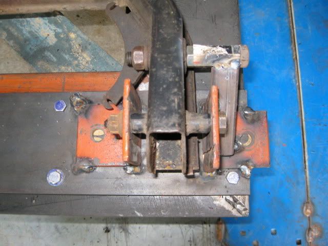
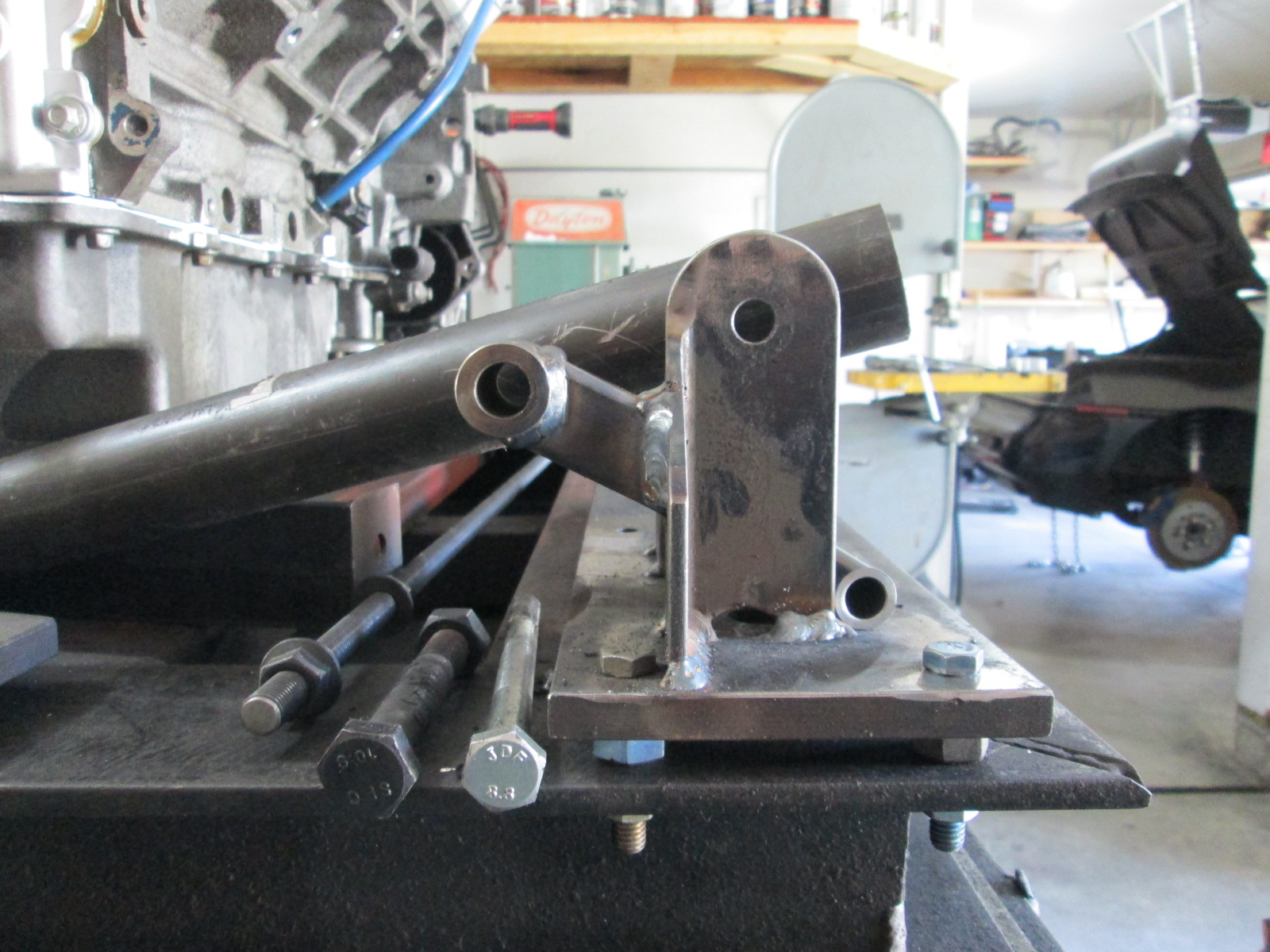
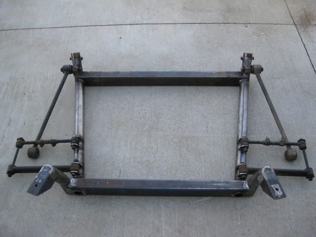
I also went ahead and reworked the front cradle attachment points on my cradle fixture. This is what they looked like when I used some scrap metal back in 2009. While they have been used many, many times since w/o issue, I didn't like looking at them, and didn't want them to be distractions for my tubular cradle build.
Old brackets:
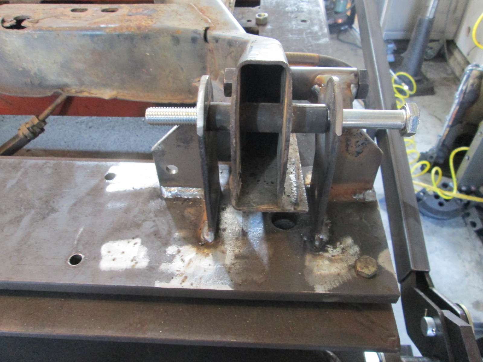
New brackets. This style more closely matches the drivetrain support brackets. I might also rework the rear cradle mount bracket - mainly because it won't clear the turbo. I would like to rework it with the geometry of the rear trunk wall included.
Sunday I plan to test out the bender!
|
|
|
|
fieroguru
|
JUN 07, 08:15 PM
|
|
It was a long day and progress doesn't seem like much...
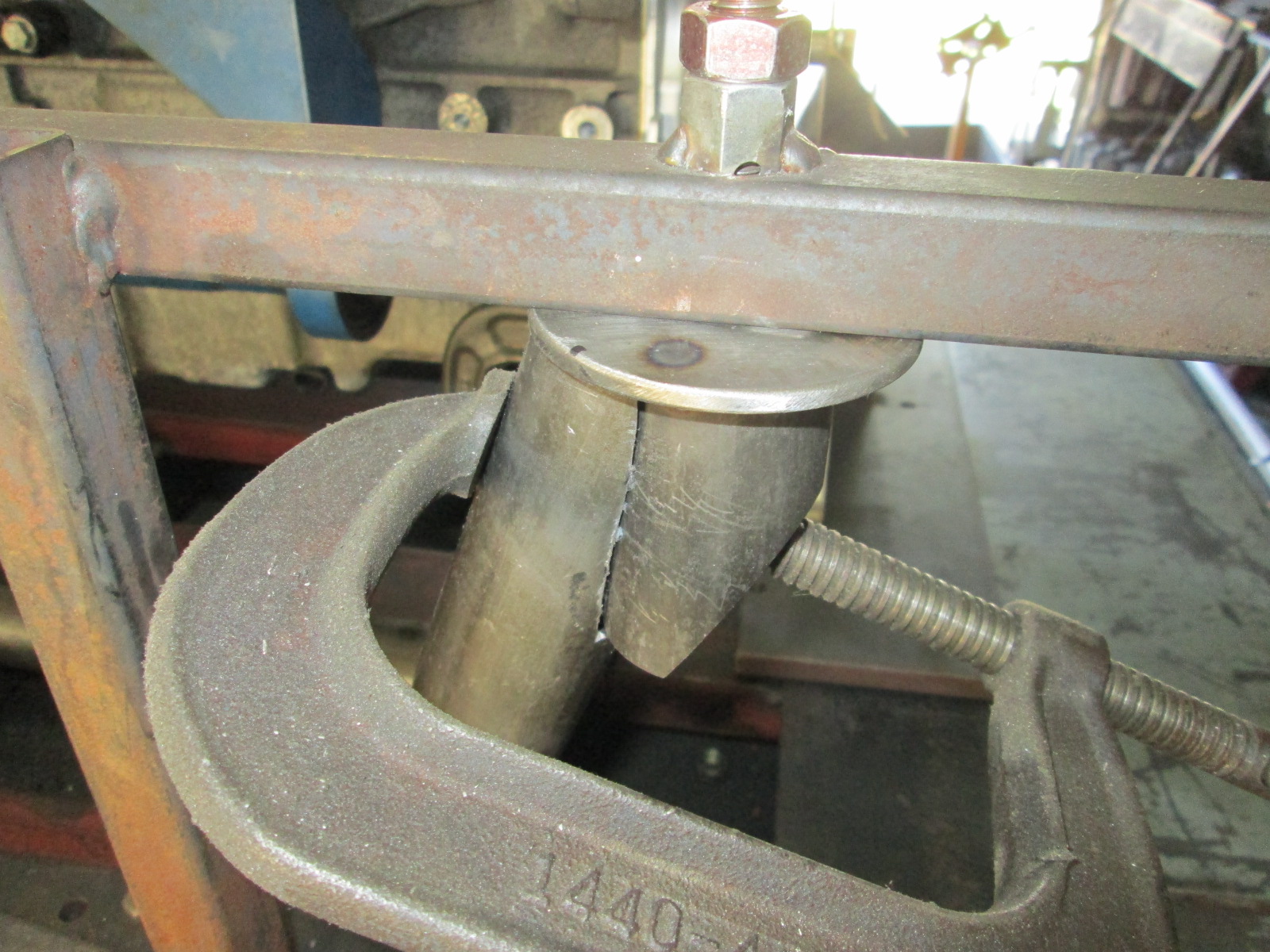
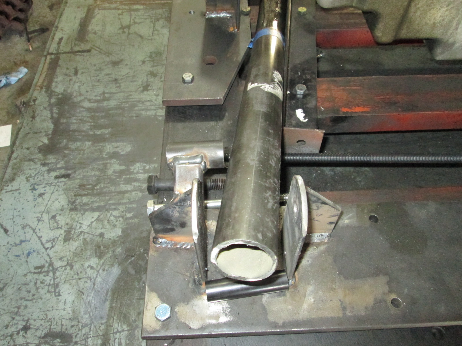
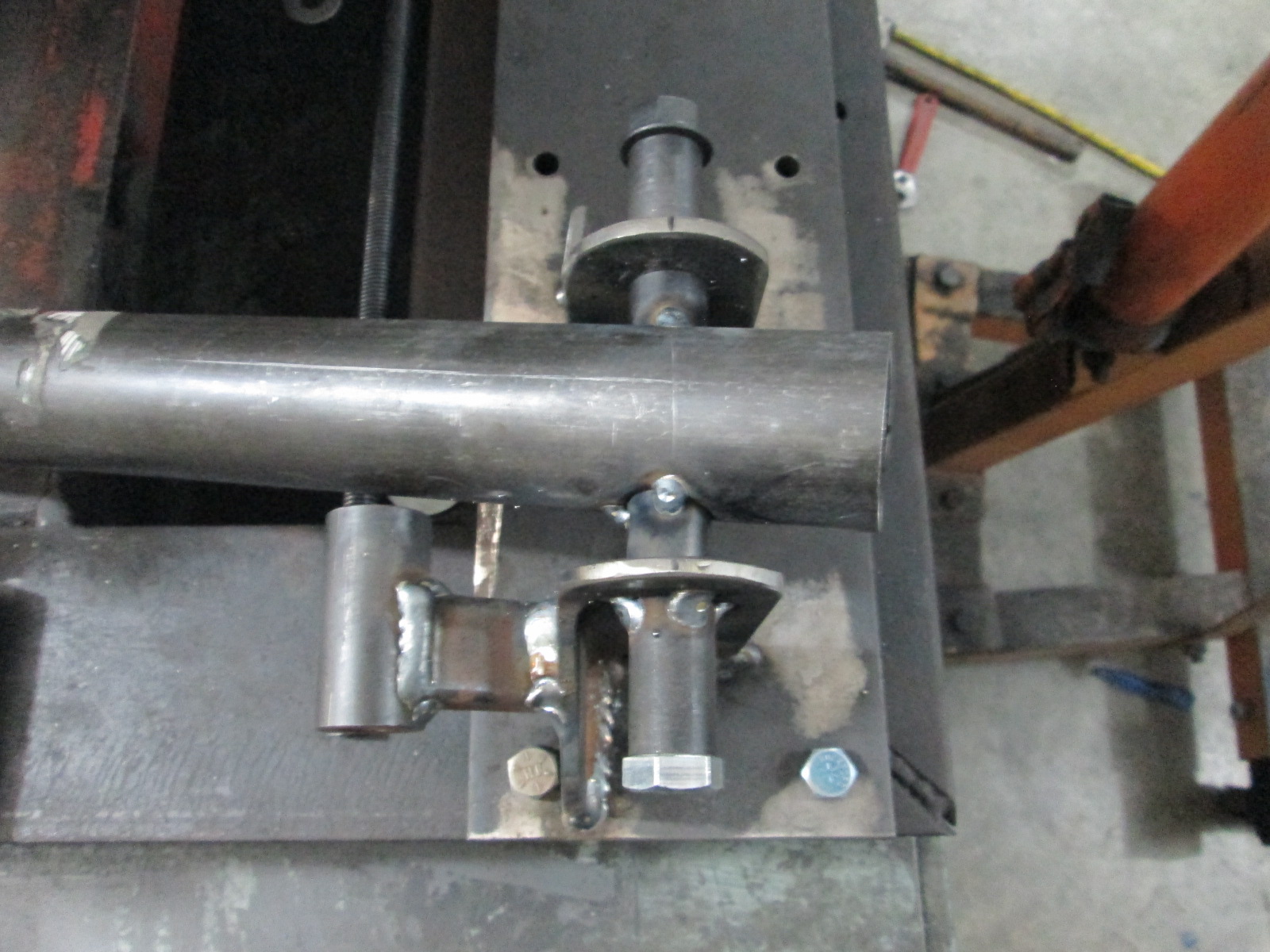
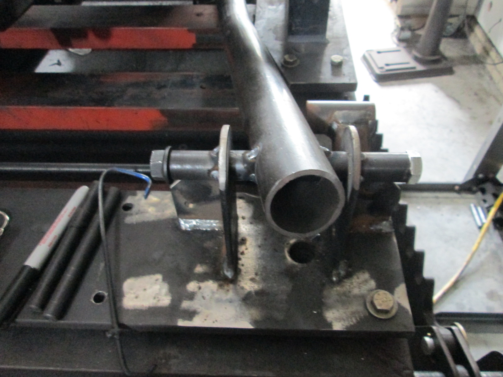
The rear cradle attachments were a fair amount of work. Had to make the top circular plate (cut squares, trim them into octagons, turn them round on the lathe). Once they were done, I cut some of the tube and put a bevel cut on it and made the two sides match with the belt sander. Then I modified a washer so the upper circulate plate would self-center to the tube and put 4 tacks to hold everything together during the mockup/fitment stage.
Once these were done for both sides, then I started on the first main tube. This is my second tubular cradle, so the fixture already had the angle plates to position the main tubes. It was mainly about bending the 90 (not quite 90), then fitting the end to the rear cradle bolt attachment. I think I had the tube in for test fit, removed for some grinder work, then install for the next test fit... about 10 times.
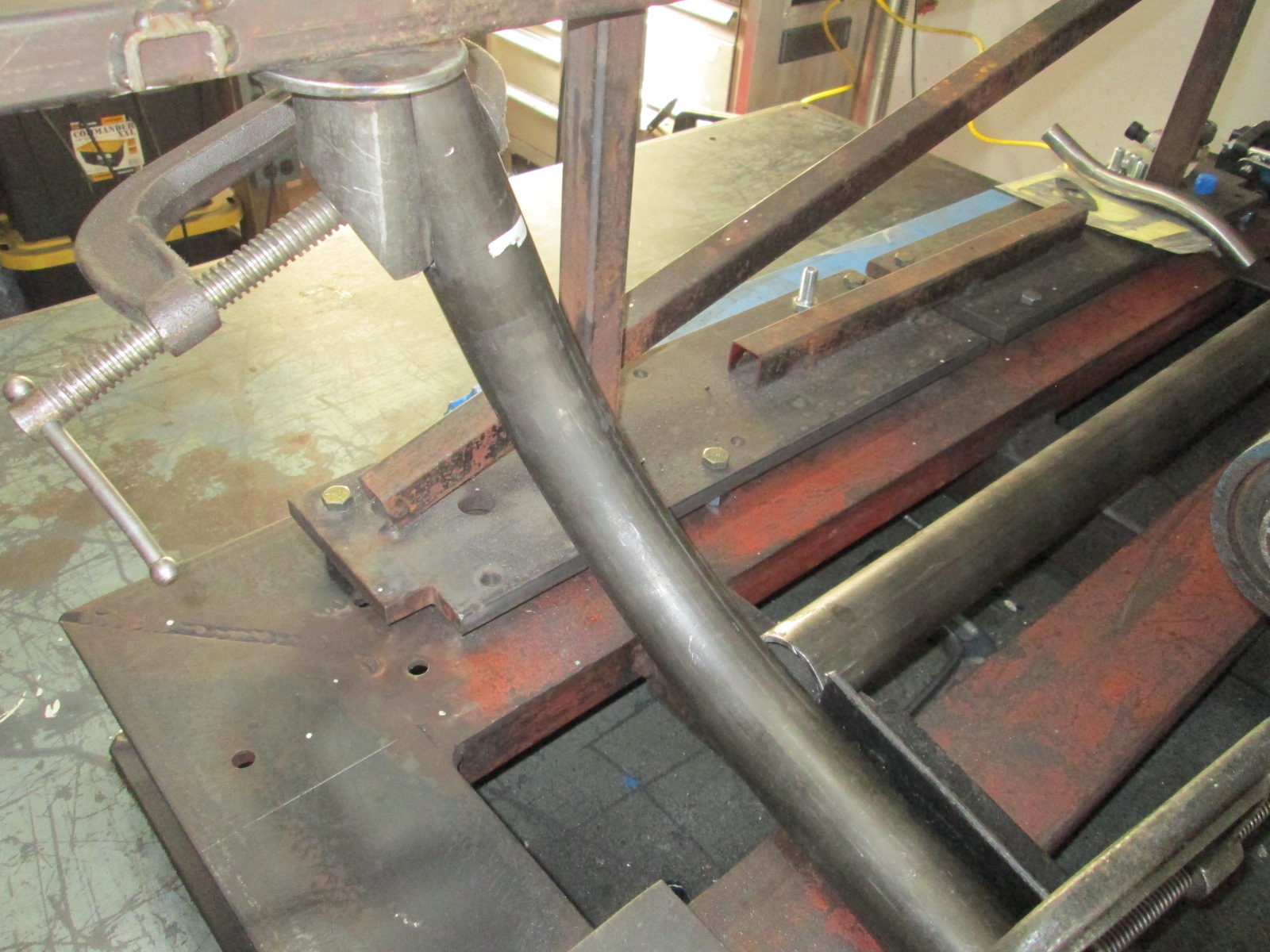
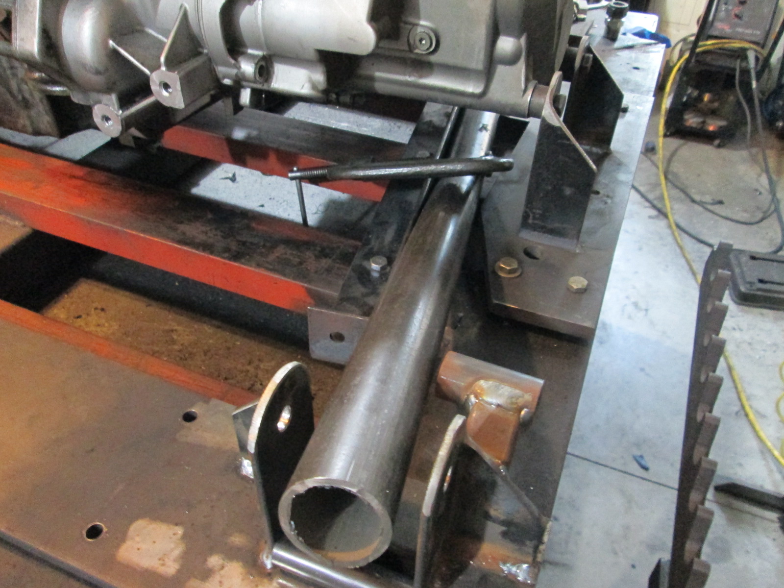
Once the rear connection point was fitted, I bend the front one. The location and angle of the bend is critical to have both the trailing link and front cradle mount sleeve in the center of the tube.
Here is an overall look at the first tube.
|
|
|
|
sourmash
|
JUN 07, 10:13 PM
|
|
That's going to be a trick setup, building a new cradle. I read a thread of someone who did this to a Boxster:
| quote | | He’s installing the engine and transmission with a custom engine cradle aided by a 3D scan of the engine and bay using an iPad with a Structure Sensor. |
|
https://engineswapdepot.com/?p=25774
That poor guy spent a couple years building a Boxster with an amped Audi 2.7tt. When he got it done, it burned due to the oil feed to the turbo leaking. He kept going though.
|
|
|
|
ericjon262
|
JUN 08, 02:19 AM
|
|
I saw in one of your pictures, it looked like you were holding aluminum pipe up to the turbo for the charge piping, if you were planning that, I would imagine tubing would be about 1/10 the weight.
I missed it where you mentioned a custom cradle, do you think you can take enough weight out or add enough rigidity for it to be a benefit?
| quote | Originally posted by sourmash:
That's going to be a trick setup, building a new cradle. I read a thread of someone who did this to a Boxster:
https://engineswapdepot.com/?p=25774
That poor guy spent a couple years building a Boxster with an amped Audi 2.7tt. When he got it done, it burned due to the oil feed to the turbo leaking. He kept going though. |
|
this guy has had his fair share of disasters but seems to keep chugging along like nothing happened...
https://grassrootsmotorspor...ri-308/148959/page1/------------------
"I am not what you so glibly call to be a civilized man. I have broken with society for reasons which I alone am able to appreciate. I am therefore not subject to it's stupid laws, and I ask you to never allude to them in my presence again."
cognita semper
https://joj2020.com/ <--- She isn't a sexual predator.
|
|
|
|
fieroguru
|
JUN 08, 07:19 AM
|
|
| quote | Originally posted by sourmash:
That's going to be a trick setup, building a new cradle. |
|
I like to keep things interesting! I built my first on back in 2009, but didn't have a good bender, which caused me to alter from the previous design. The new one will be even better.
| quote | Originally posted by ericjon262:
I saw in one of your pictures, it looked like you were holding aluminum pipe up to the turbo for the charge piping, if you were planning that, I would imagine tubing would be about 1/10 the weight.
|
|
That was a schedule 10 stainless bend I had left over, I won't be using it for the cold side. It will be 16ga tubing of some kind (stainless or aluminum. I would prefer aluminum, but I can weld stainless much, much better).
| quote | Originally posted by ericjon262:
I missed it where you mentioned a custom cradle, do you think you can take enough weight out or add enough rigidity for it to be a benefit?
|
|
The primary goal for the cradle is to provide additional clearance for the rear sway bar to clear the turbo and the AC pulley to clear the frame rail. Secondary goal is to keep the engine/transmission mounts simple. 3rd goal is to match the tube cradle that will be going in front to fit the custom front suspension and awd differential (couple years off still). Any minimal weight savings I come across will simply be a bonus.
Anyone taking the time to build a tube cradle thinking they are going to significantly reduce the weight hasn't ever weighed an 88 rear cradle. The bare stock cradle is 50 lbs stock w/o the uprights and links. The tube cradle as shown above was 40 lbs, but not complete at that stage. My current cradle is a little heavier that stock (stock main rails, 2/3 front/rear cross-members), so 10-15 lbs vs. current is about the maximum weight savings potential since I am sticking with .120 wall tube for strength, stiffness, and durability. I saved more than that switching to the dyna-batt and moving it forward, at a significantly lower cost.
|
|
|
|
fieroguru
|
JUN 12, 09:13 PM
|
|
When you have the first rail done, you have a template, but you also have to make both sides match... So in the end, the other side isn't really any quicker...
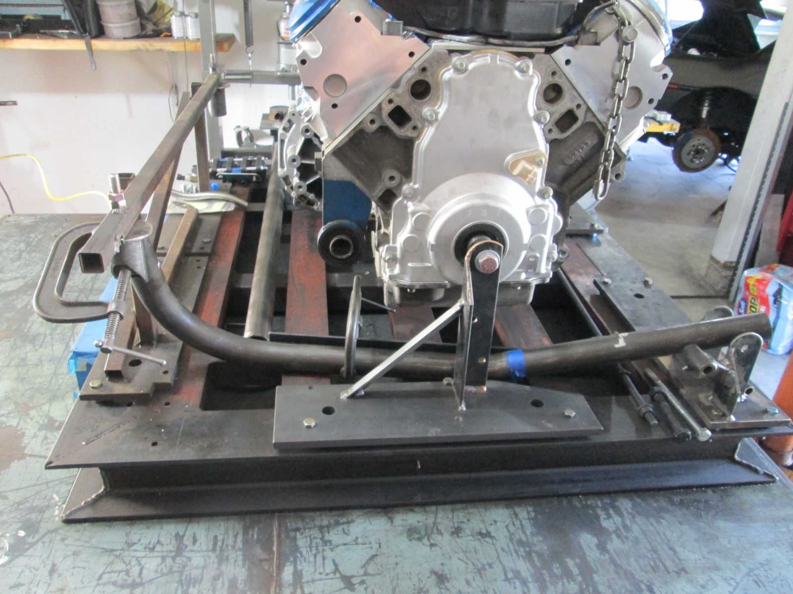
Here is a mock up of the rear crossmember tube. I also positioned the rear suspension pickup plates (proper position front to back, but pulled out about 4" because it won't fit with the drivetrain support plates). You can see the tube will have good alignment with the rear suspension link, but I will likely bend this tube so it will attach further forward and closer to the middle point between the two lateral links. The transmission side will likely be the limiter on how forward I can get the tubes and still clear the differential housing.
My CNC plasma table arrived this week. Reports are that it takes a few hours to put together, but I think I will continue to focus on the cradle this weekend and work on the table after work next week.
|
|
|
|
fieroguru
|
JUN 13, 06:59 PM
|
|
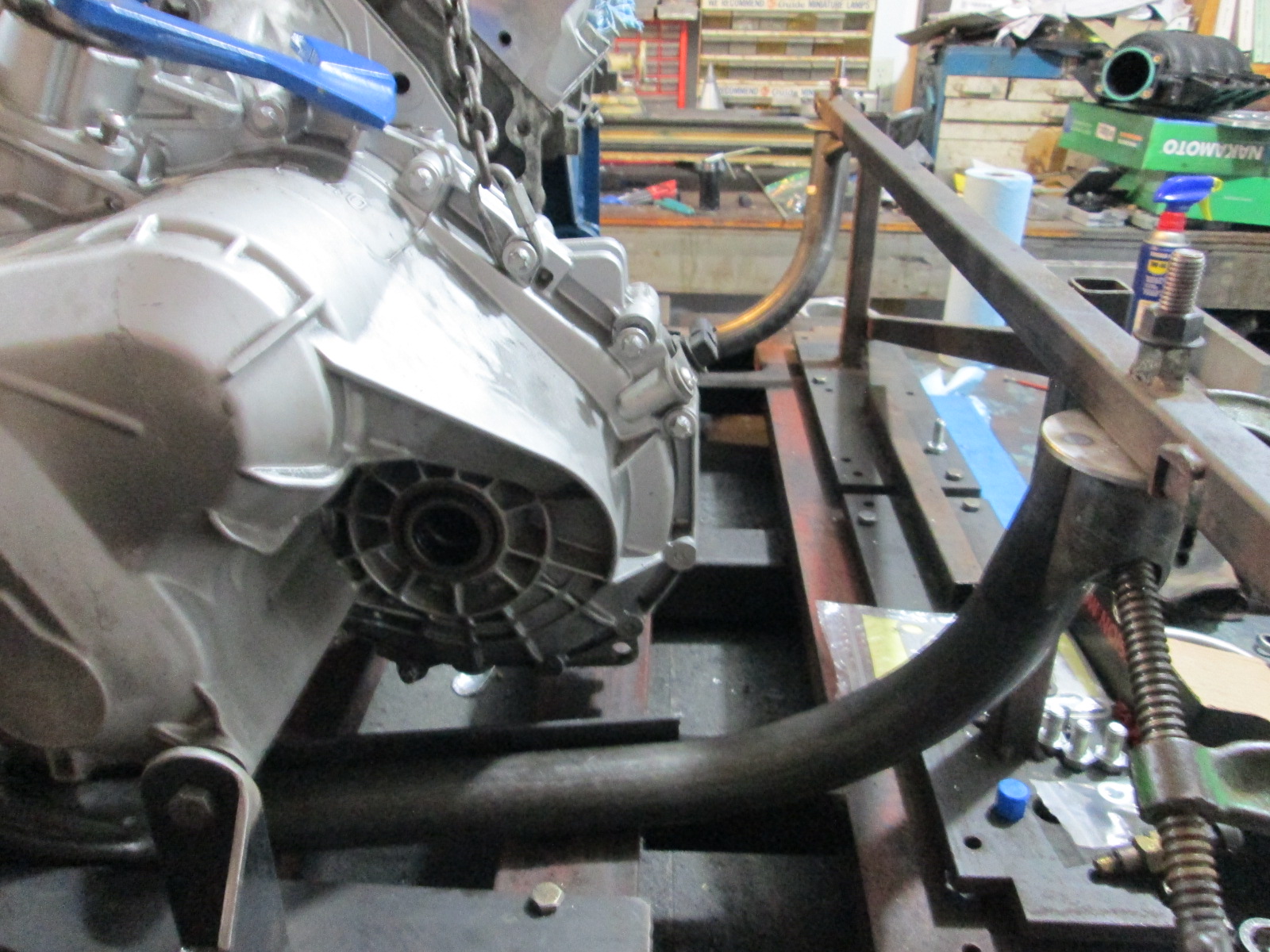
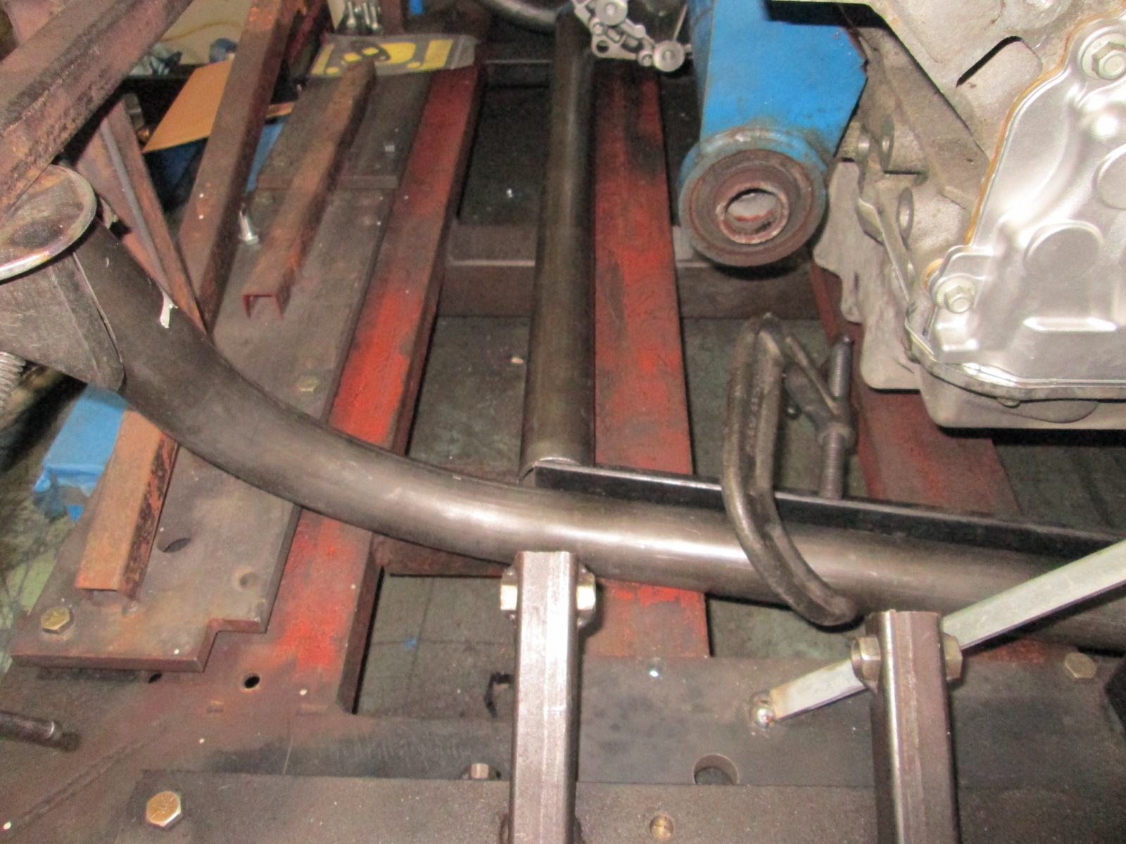
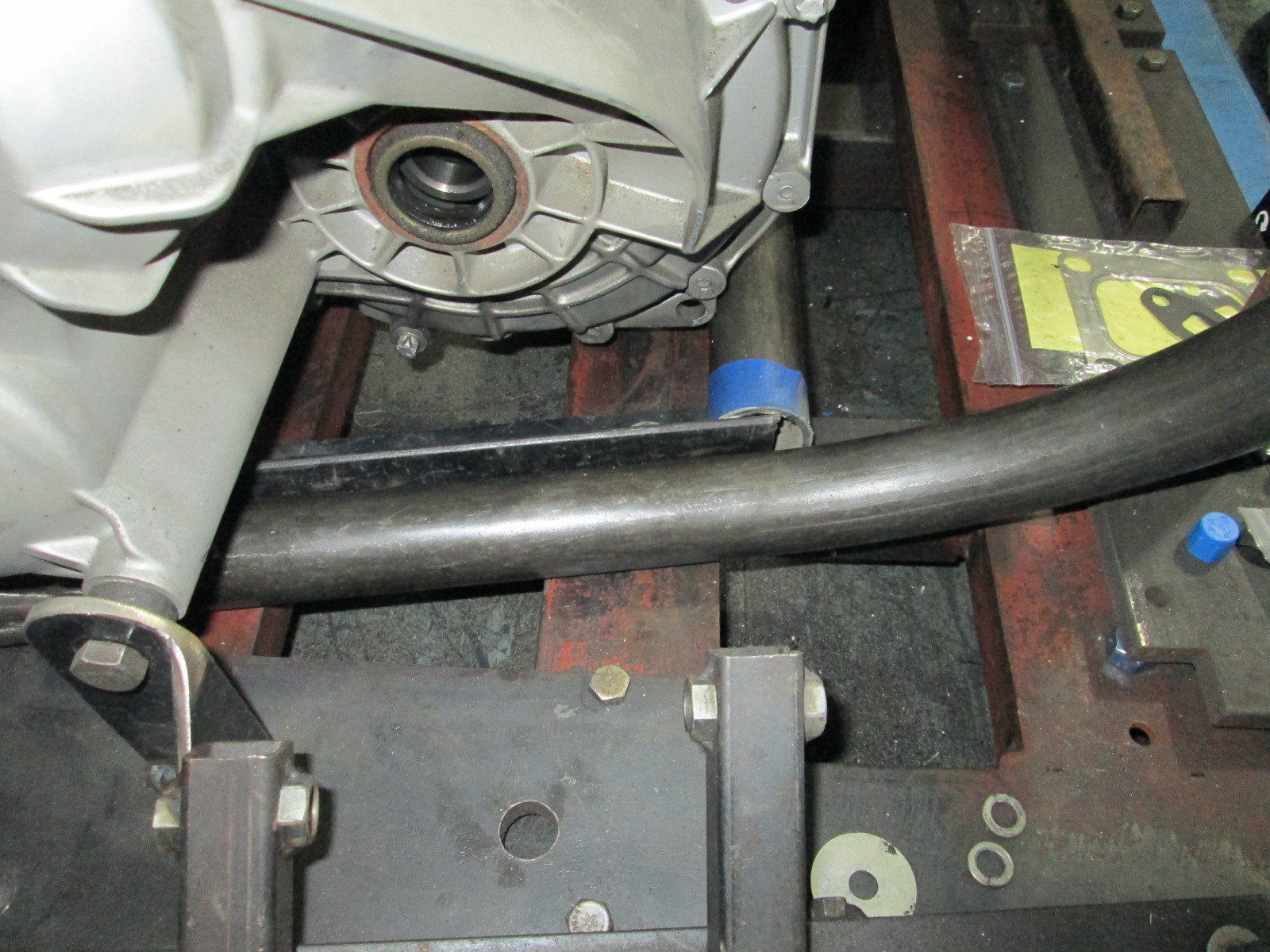
Tacked in the front cradle mount sleeves to help hold the main rails in position:
I tacked the rear cradle mounts to the main tubes, bent and shaped the rear crossmember, tacked it in place and clamped it down to keep the cradle in position.
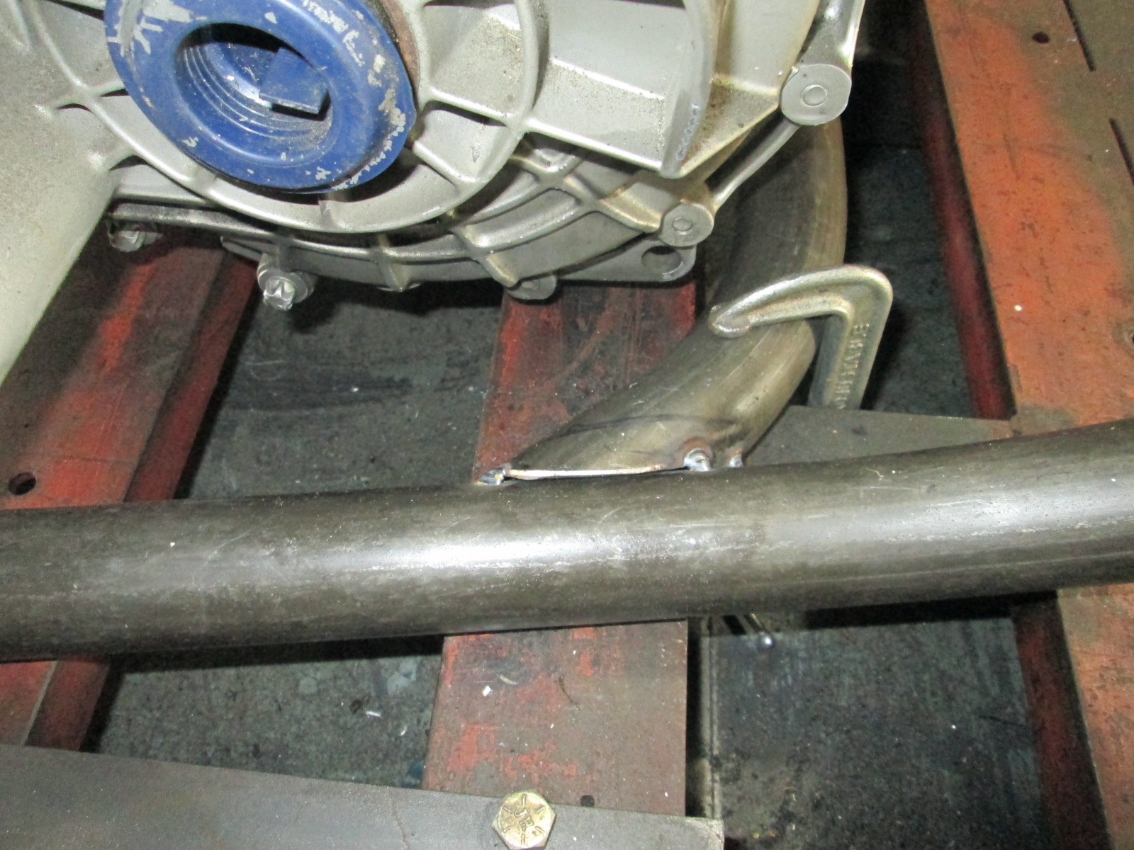
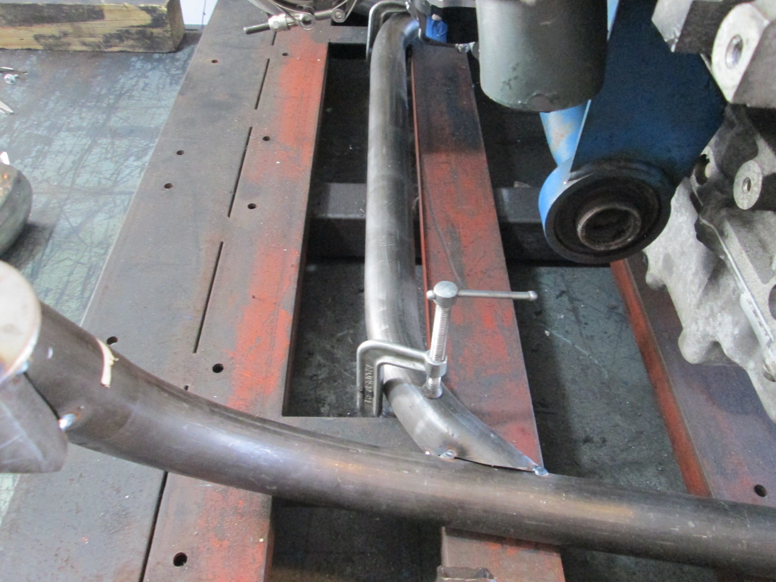
Then removed the rear cradle location fixture so I could install the turbo and check for sway bar clearance.
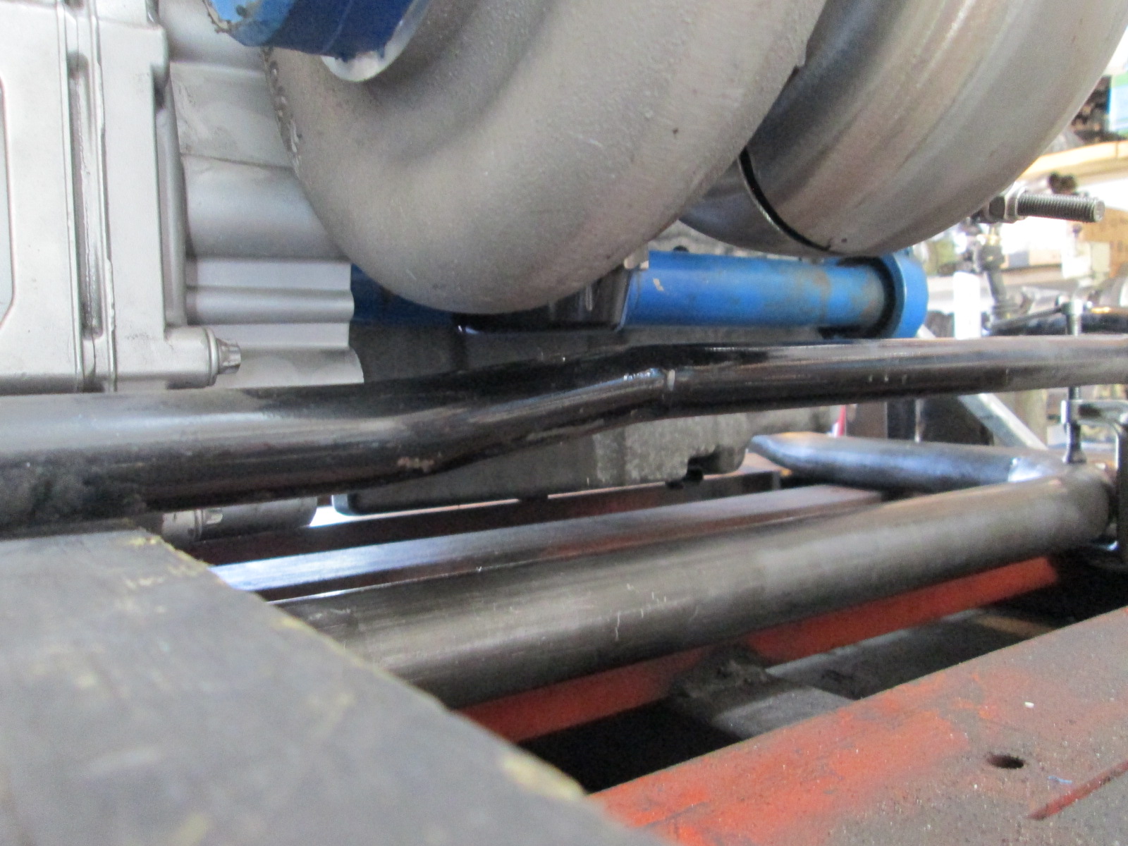
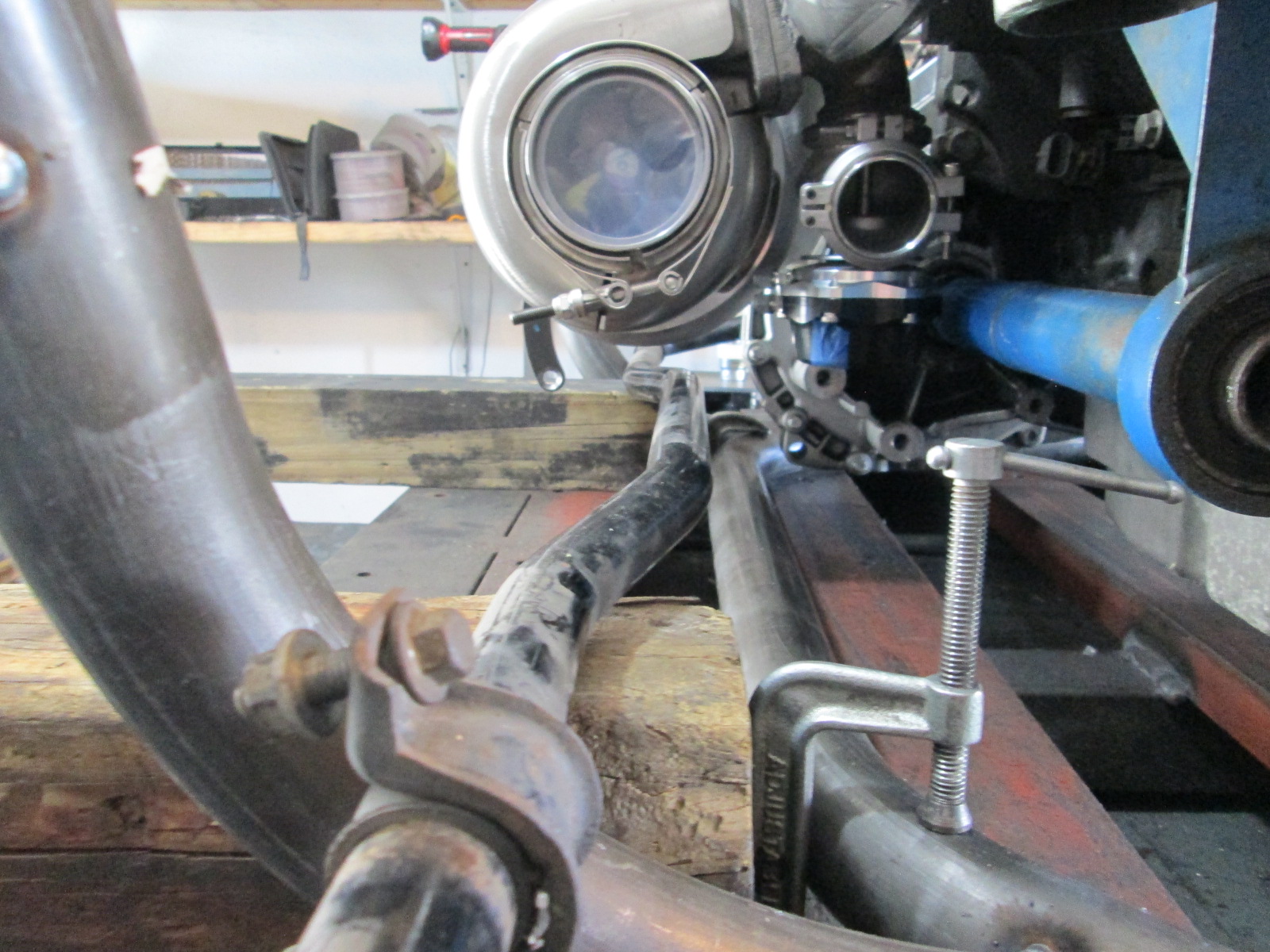
The scribe on the I beam fixture is the stock sway bar mounting surface/position (front to back).
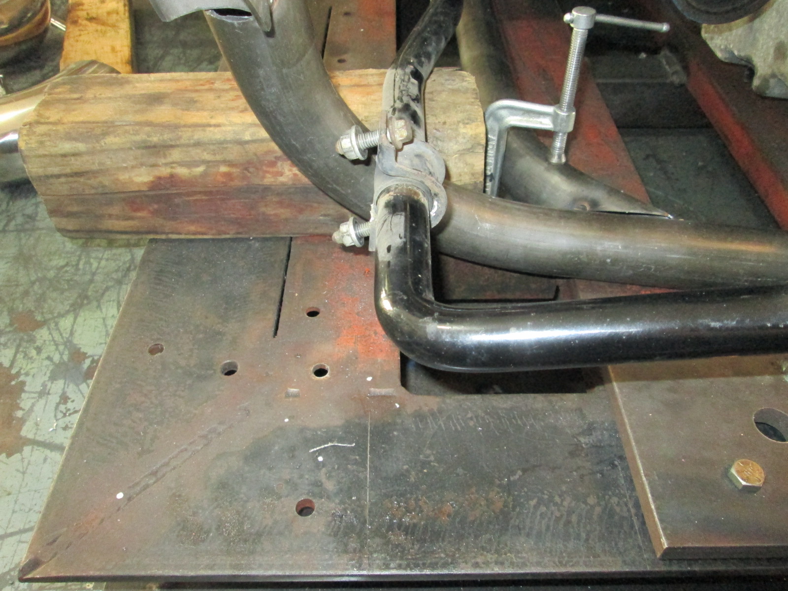
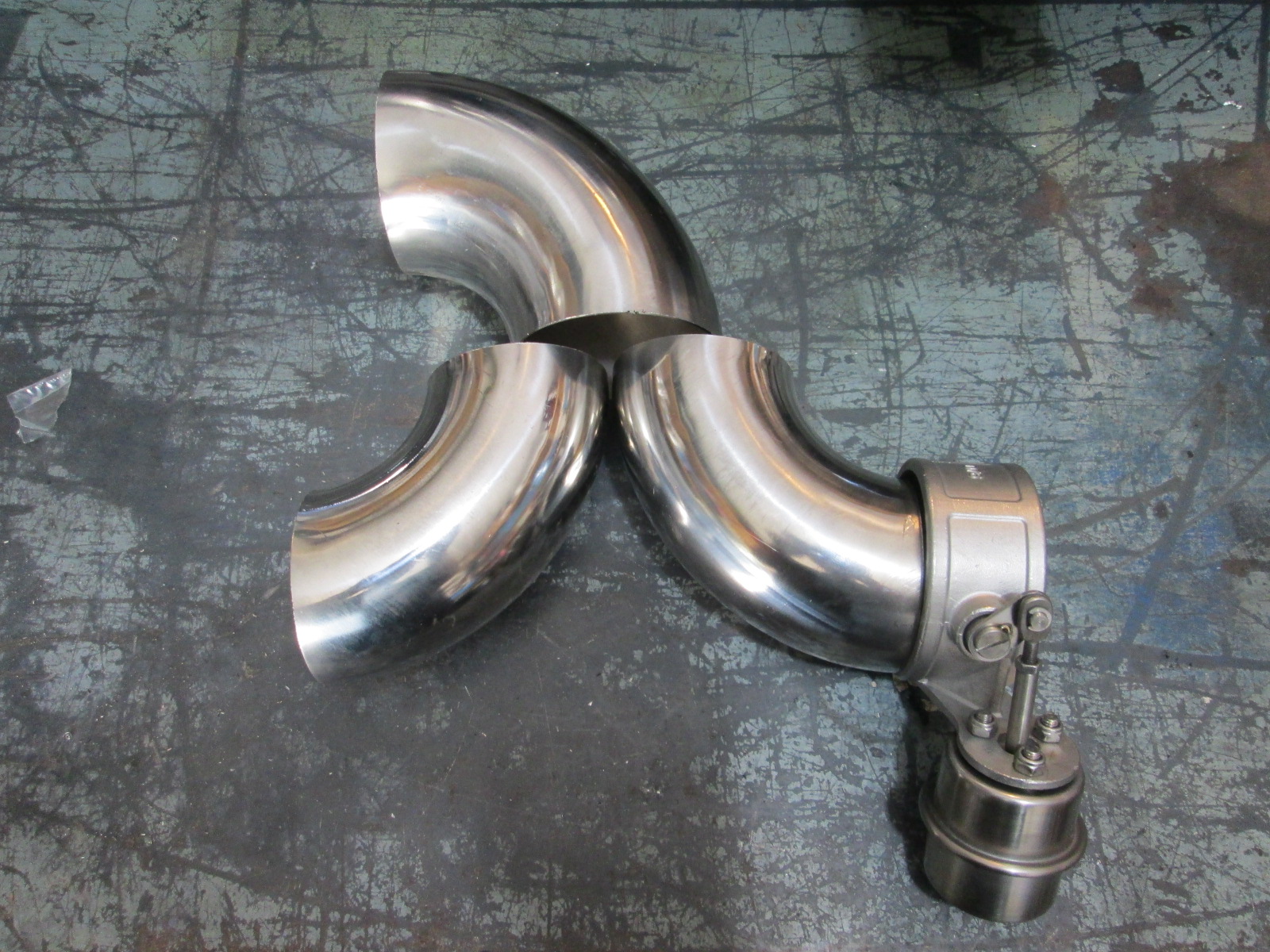
Then I mocked up some of the exhaust bends for measurement and fun. Looks like I have about 7.5" for a 3.5" muffler between the turbo and the exhaust bend so the magnaflow 14160 with a 6" body will fit. Ideally I want to run two mufflers to help keep the car quieter (not that a 3" perforated tube exhaust will ever be quiet...). The 3.5" muffler will also help take the edge off when I run with the 3" cutout open (un-muffled exhaust isn't for me). The 3.5" muffler won't leave room for the wastegate exhaust to joint back up before the 3/5" muffler, so I have sourced a 2" stainless perforated tube muffler for it. With the wastegate having its own muffler, I will have the option to merge it after the 3.5 muffler or just vent it to atmosphere.
|
|
|
|
fieroguru
|
JUN 14, 06:47 PM
|
|
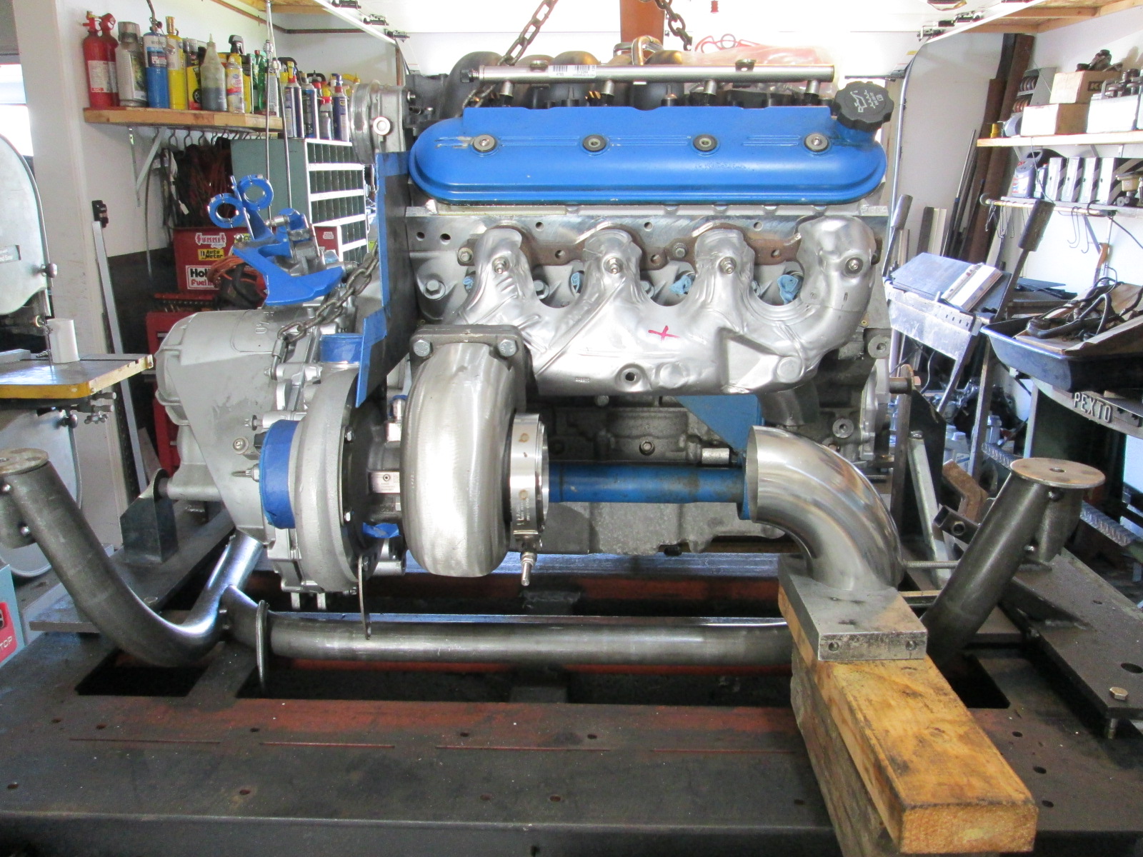
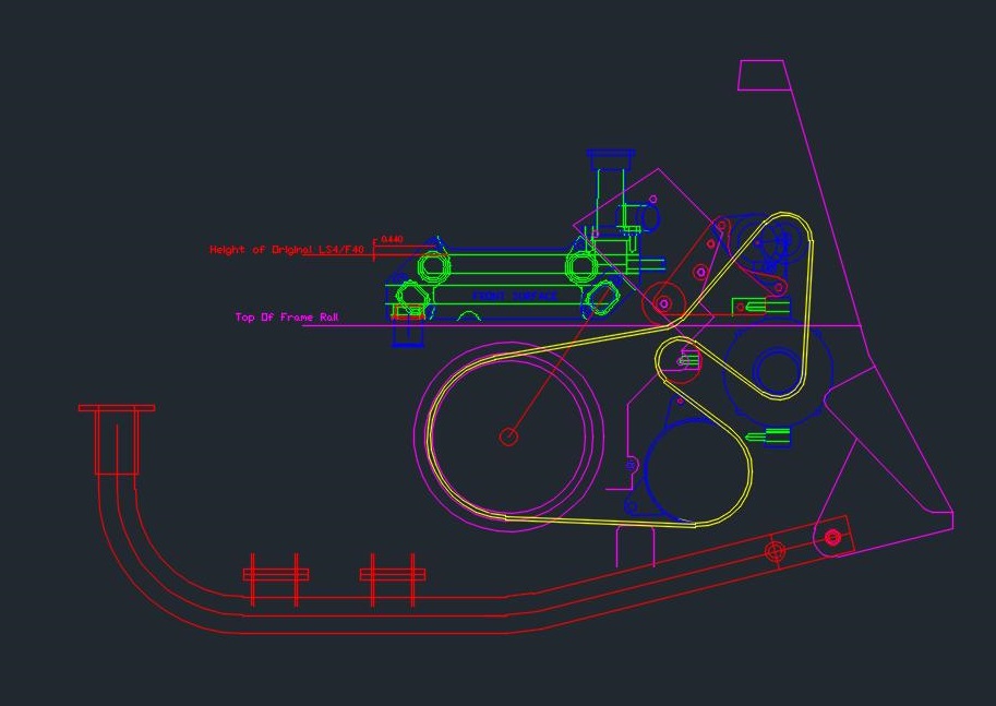
Before I can locate the front crossmember on the cradle, I really needed to nail down the accessory drive. I am going to go electric for now with a pump mounted up front, so that allowed me to raise the alternator and ac position slightly. It was really handing having the chassis with the mockup engine in the exact same position as the engine on the cradle. I made an adjustable alternator holder, adjusted it in the chassis to the proper location, then I could mount it on the fixture, take some measurements and draw everything up in autoCAD.
New alternator and AC positions:
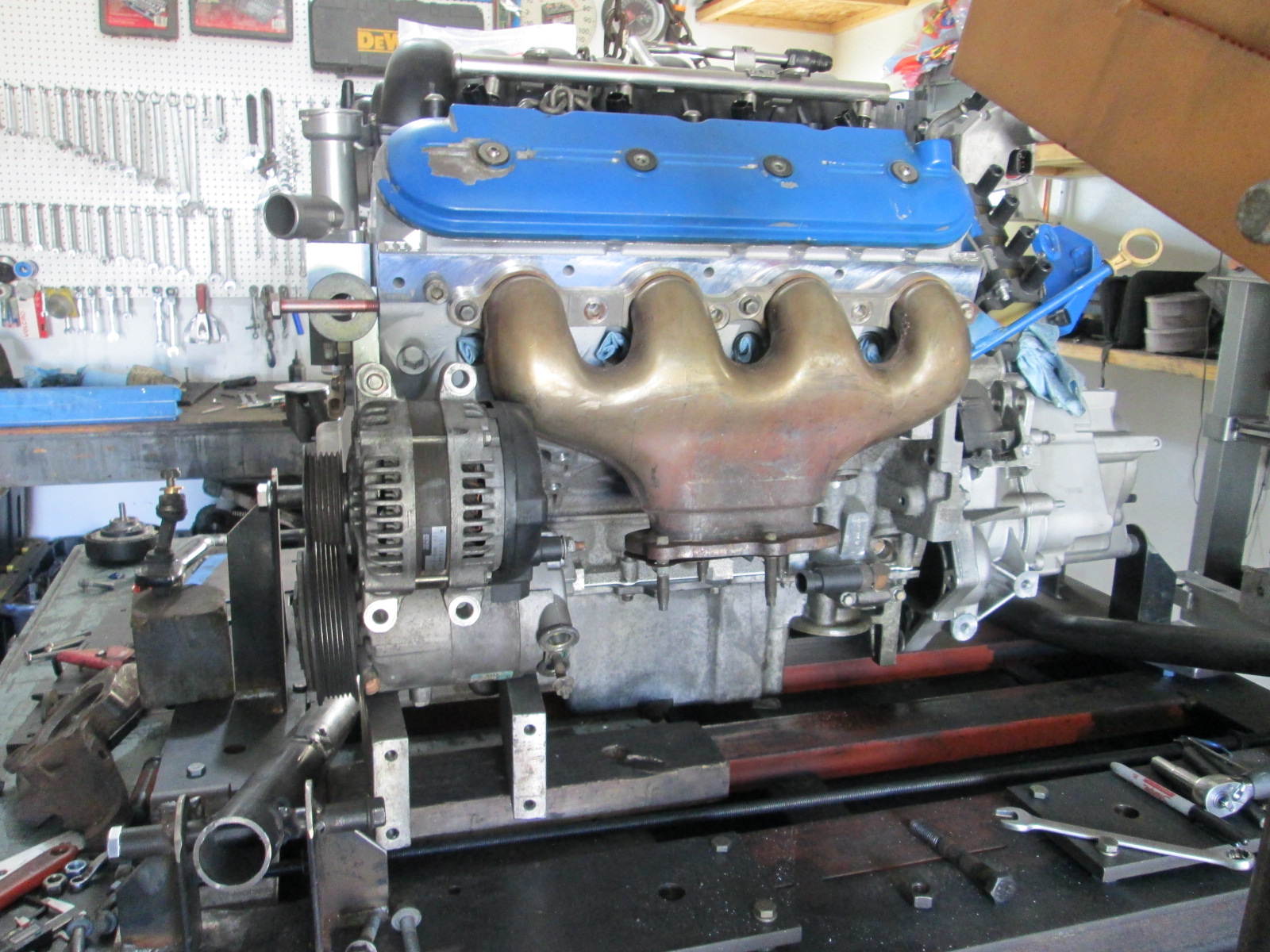
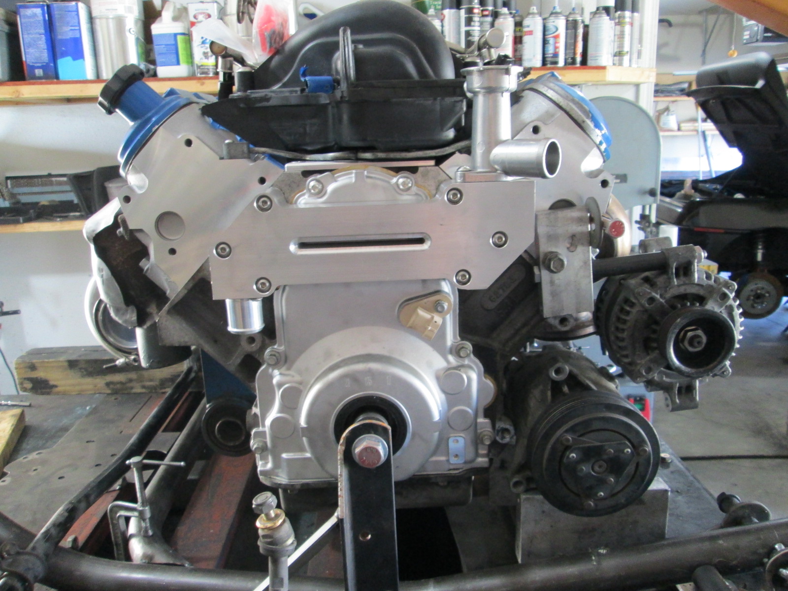
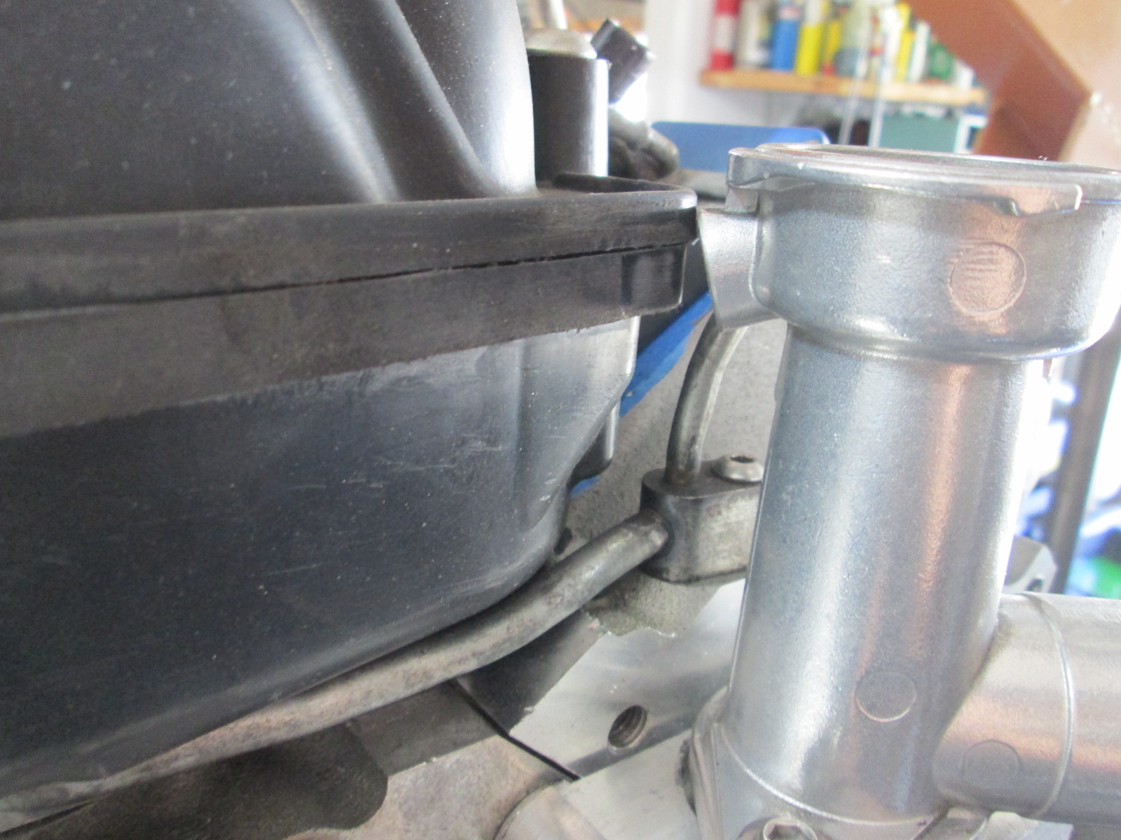
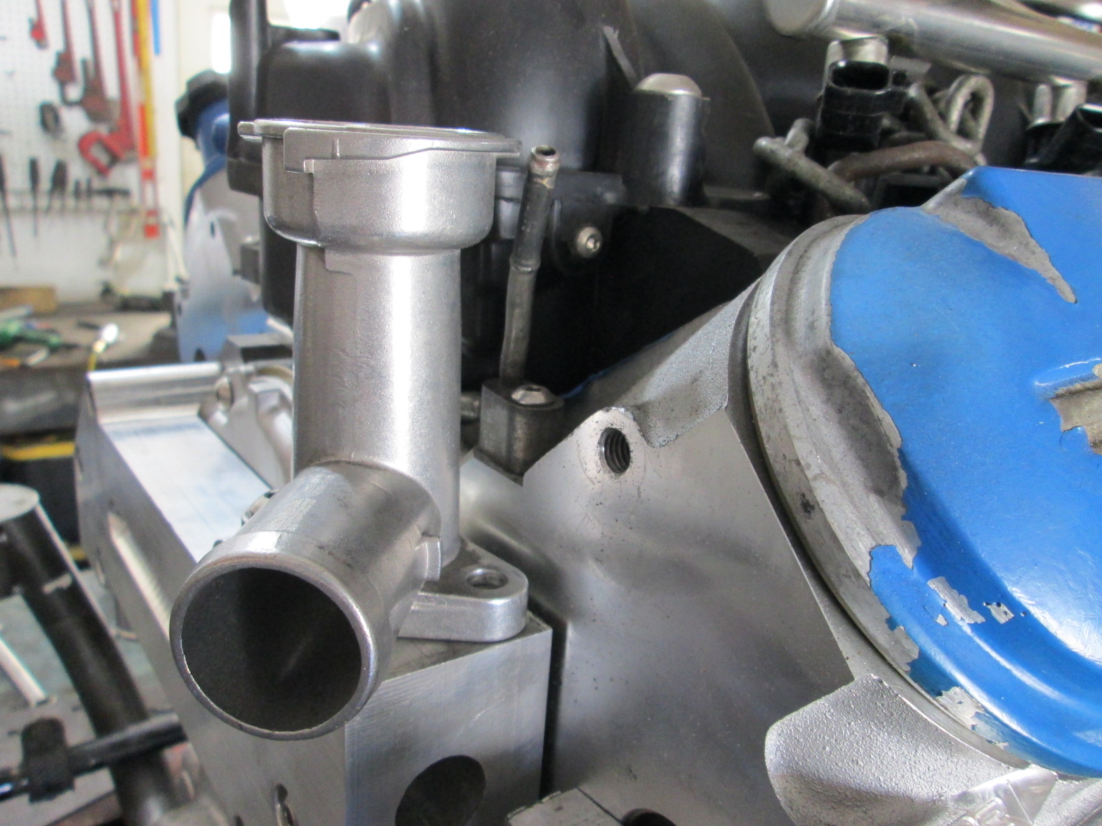
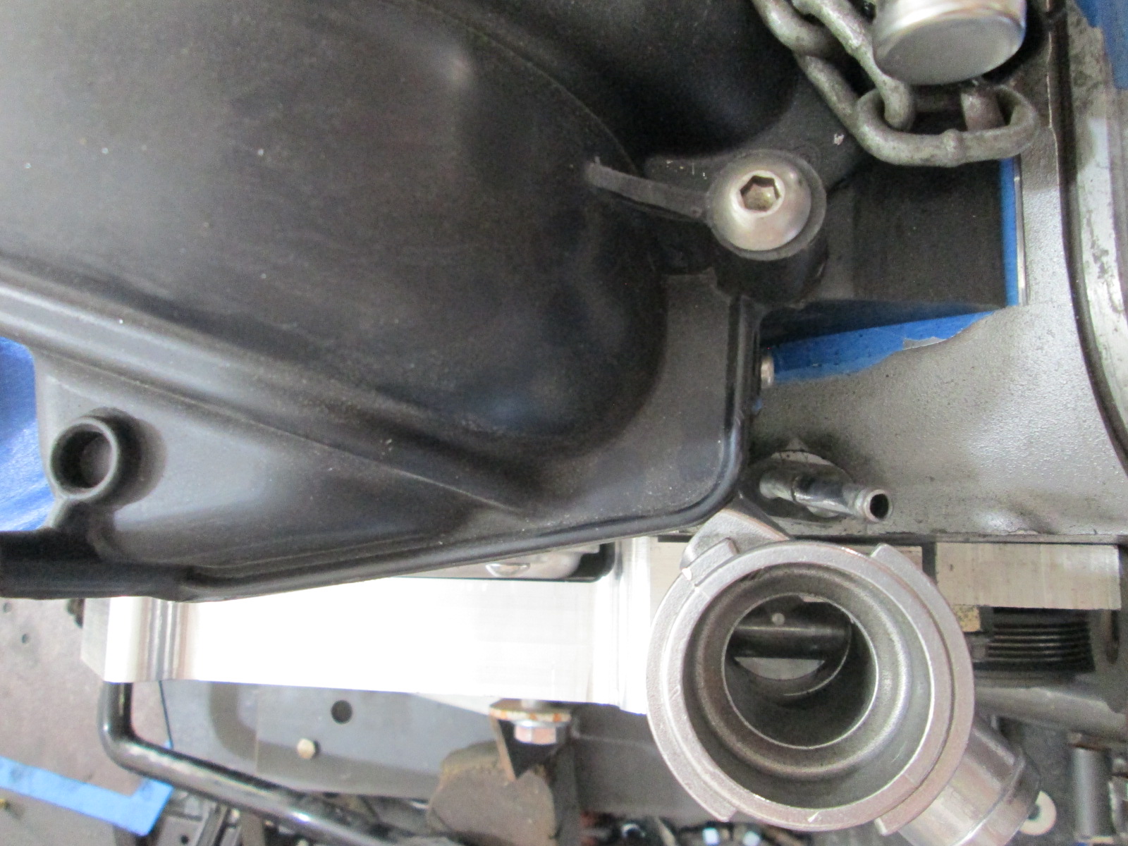
I am glad I decided to install the water manifold/thermostat housing... The Dorman LS2 intake interferes with the nipple boss on the water neck. Also, the steam vent line was in the way as well, so I bent it out of the way for now. So this is another area I will have have to revisit and come up with some additional space.
Pretty happy with the progress this weekend. I also ordered the 3.5" x 6 magnaflow muffler, the muffler for the waste gate, some aluminum plate for the new alternator bracket (all drawn up in autoCAD), and the two idler pulleys that will allow me to reuse stock bolt locations on the engine.
|
|
|
|
KissMySSFiero
|
JUN 17, 04:16 PM
|
|
Did you abandon the mechanical water pump manifold you were designing a while back?
Are you putting in a different clutch this time?
Nice work. ------------------
SSFiero@Aol.com
|
|
|
|