
 
     |
| Blooze Own: An F355 Six Speed N* Build Thread (Page 82/126) |

|
Bloozberry
|
SEP 27, 10:17 PM
|
|
Thanks northeastfiero, yours is looking great too.
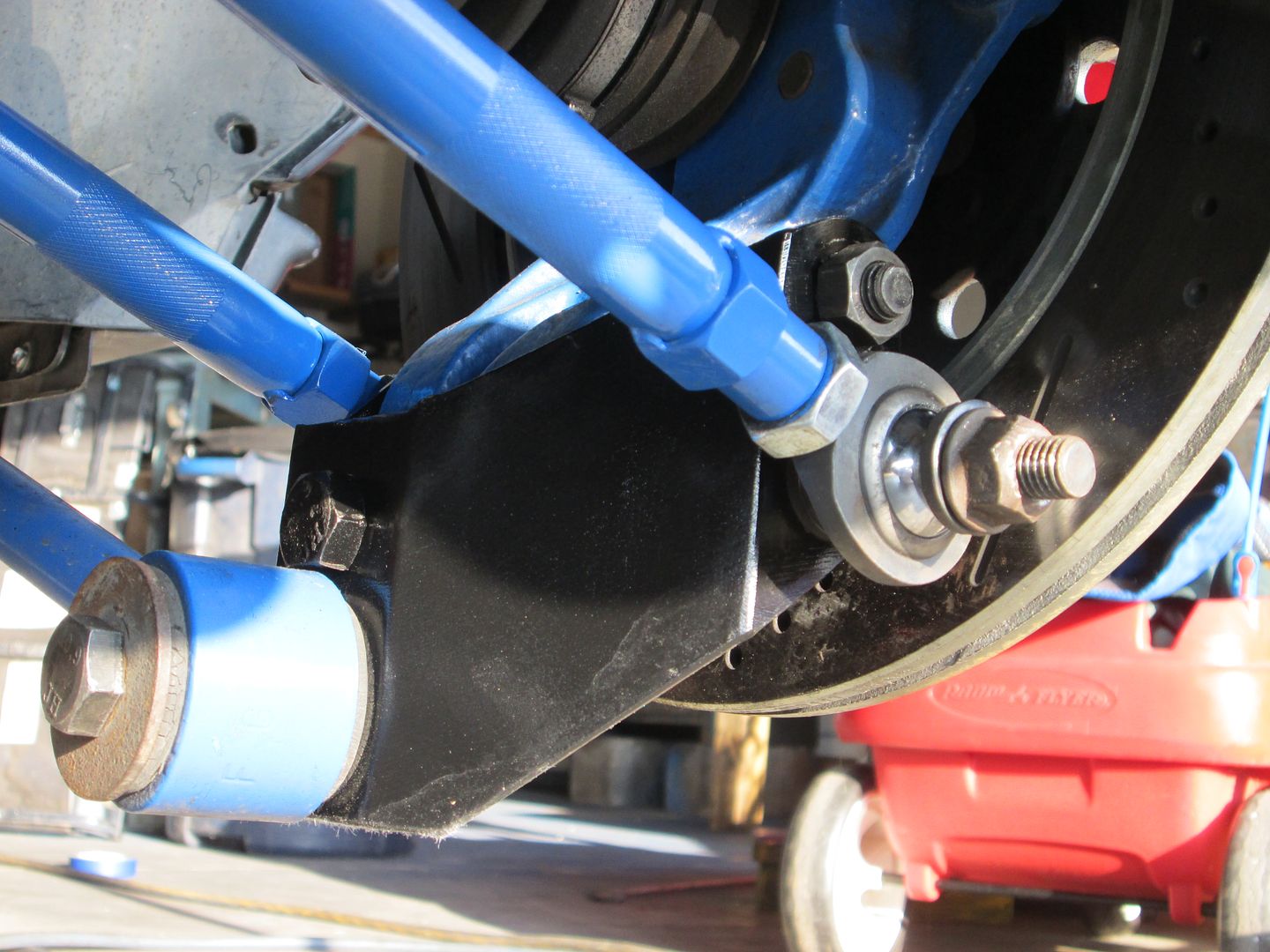
I've been busy over the last two weeks modifying the lower and upper link mounts for the flipped knuckles... and so far I've only managed to complete this work on the driver's side. It doesn't sound like much but I like doing things two, three, and sometimes even four times before getting it right! I started by cutting off version 1 of the lower link mounts from the cradle, measuring their new locations to accommodate the flipped knuckles, fabricating one new mounting ear because one ear of the forward mount now sits on the sloped part of the cradle rail, and tack welding it back all in place. All the mounts were moved a further 28 mm forward on the cradle. Here's the latest configuration, although I will probably weld a gusset or two to the new long ear in the foreground:

With the lower end completed (again), I started reworking the upper mounts attached to the top of the lower main frame rail. I had already made the upper mounts for the non-flipped knuckles, but they were no longer any good because flipping the knuckle meant they'd have to be moved roughly 65 mm further backwards on the rail. Since the rail's profile changes rather significantly in that area, the old mounts became useless. I also decided to take bubbajoe's advice and give the upper mounts a larger surface area to spread the loads onto the stock frame rail. Rather than welding the upper mounting ears directly to the rail's thinner metal, I decided to add a piece of 2" x 2" x 1/8" angled steel along an 18" stretch of the rail to anchor the mounting ears.

I then measured, cut, shaped, drilled, and tacked the four new upper mounting ears to the angle iron:

The forward mount sits at a 51 degree angle to the centerline of the car, but the frame rail also diverges from the car's centerline in that area by 7 degrees, so it took me a few tries before my cardboard templates actually fit properly with the hole at the right height, angle, depth, and lateral coordinates. It also took several attempts to make the metal mounts since they also needed correctly bevelled edges where they met the vertical parts of the rail, not to mention you need to measure twice and cut once. On one attempt, I managed to get a perfectly fitting part, then promptly drilled the hole 10 mm's lower than it should have been.  Anyways, this is the view of the upper forward mount as seen from the engine bay looking outwards: Anyways, this is the view of the upper forward mount as seen from the engine bay looking outwards:

Here are all four mounts on the driver's side: upper, lower, fore, and aft, finally tacked in place and ready for some links:

The next step was to build up the links to the correct lengths. As I mentioned earlier, I like to do things several times before getting it right. In this case, I set about screwing the jam nuts on all the rod ends, then threading the rod ends into each of the swaged tubes. I had printed a legend to remind me how long each link needed to be eye-to-eye and immediately ran into a problem. It seems when I ordered my tubes, I had forgotten to take into account the length of the jam nuts so most of my tubes were too long. I could have cut them down, but I like to go by the rule of thumb that a rod end should be threaded into a swaged tube over a length equal to 1.5 times the diameter of the threads. Luckily I only needed to order six new tubes out of ten, adding a mere $100 more, and one additional week to the design (I've amended the list of parts I posted earlier to reflect these changes). So here they are... all ten links dialed in to the correct length and ready for installation:

I then simply attached the two upper and two lower links to their respective mounts on the frame using a 1/2" diameter fine threaded grade 8 bolt and a pair of rod ends spacers per mount. I made sure to buy bolts that were unthreaded along the length between the mounting ears, which for the most part, meant buying extra long bolts and cutting them down to fit correctly.

The knuckle, brakes, and tire mock ups are next... so stay tuned!
|
|
|
|
fieroguru
|
SEP 28, 08:07 AM
|
|
Looking good!
It might not be much of an issue for you since all but one of the links per side will be fixed length, but you may want to consider putting some flats on the toe link tubes so you can hold them with a wrench to tighten the jam nuts. I didn't do this when I installed mine, and ran into issues getting them tight enough, so when they were out again, I took a large nut, bored the center to fit over the tube and then tacked it to the tube.
|
|
|
|
Bloozberry
|
SEP 28, 07:22 PM
|
|
So the knurling on the tubes didn't cut the biscuit eh? Somehow I'm not surprised, but I like your solution. Thanks for the tip!
I usually try to post pictures of actual progress rather than mocking stuff up to make it look like I'm further ahead than I really am, but this post is a different story. I just can't contain myself. With the four lateral links installed (at least temporarily while I double check other measurements) I couldn't help mocking up the rest of the suspension to see how it would look. If performance is king, then aesthetics is a queen, and I think this system is going to be a royal couple. But judge for yourselves...
First, I installed the knuckle to the lower links and then to the upper links:

Then I propped the knuckle up on blocks at ride height, added the shock push rod to the top of the knuckle (while holding the other end of the rod up with some baling wire), then finally threw on the trailing link even though I haven't made up the forward mounting bracket yet. This is how it looked:
View looking forward from above:

View looking aft from above

Side view looking aft

Rear view

View from inside engine bay looking out

Pretty sexy eh? I was on a roll so I installed the 12" C4 rotors for a snap shot:

Then added the rear wheel and tire combo for a peek into the future:

And checked clearances (and rear views!)

And stood back for an overall impression:

I like it. Now I'm really looking forward to building up the shock bell crank system and adding the coil overs.
|
|
|
|
RCR
|
SEP 29, 08:54 AM
|
|
The whole thing looks great, but this shot is hot:

Bob
|
|

|
ccfiero350
|
SEP 29, 12:37 PM
|
|
|
Great job! Did the actual suspension track as well as the graphs depicted through its range of motion? ------------------
yellow 88 GT, not stock
white 88 notchie, 4 banger
|
|
|
|
Bloozberry
|
SEP 29, 04:51 PM
|
|
Thanks RCR and ccfiero350. I can't answer your question firsthand yet ccfiero. With only the two parallel lateral links at the bottom, the knuckle is still free to twist at the lower end. I need to get the front end of the trailing link hooked up to make it behave.
PFF member northeastfiero jumped the gun and is further along with the fabrication of this design than I am though. He reported no binding over 6" of travel, though he may or may not have used the exact same coordinates as me since his rear frame is significantly different, and I changed my design to the flipped knuckle approach after he had already completed his in the original configuration. I believe he's flipped the knuckles on his now too but hasn't reported back whether he ran into any problems.
|
|
|
|
Yarmouth Fiero
|
SEP 29, 08:09 PM
|
|
This all looks awesome Blooz. I love seeing a well thoughtout design coming to life so precisely. Congratulations on your latest progress.
So....... soon I'll be able to get your final track widths because I'm getting ready to pull the trigger on my suspension purchases. 
|
|
|
|
jb1
|
SEP 29, 10:28 PM
|
|
|
you really have skills.. This has to be my favorite build thread.. ------------------
87 GT
series 1 3800sc (7.597 @88.53 1.579 60ft)
(series II swap in progress)
85GT Northstar/ 4t80e
86GT 3800 n/a
My Build
|
|
|
|
Bloozberry
|
OCT 04, 10:32 PM
|
|
Thanks YF and jb1... it's always motivating to read comments from other people! 
The next thing I decided to puzzle out was the mounting system for the bell crank. My earlier drawings are noticeably sketchy in this area because I hadn't quite figured out how I was going to go about it. It was very difficult to visualize the physical space constraints for the bell crank mount without a 3D model, so I waited until now to try to figure it out.
I played around a fair bit with different concepts but most designs only work well on the driver's side where there is a lot more empty space above and around the transmission than there is on the passenger side where the engine seems to occupy every square inch. Also, the mount has to stay clear of the wheel and tire and the control links as they move through the entire range of jounce and rebound, plus keep clear of the swinging bell crank and not interfere with the shock & spring either. I've come up with a plan that I think will work fine on both sides though... it involves a simple heavy-duty pillar rising up from the top of the lower frame rail and having the bell crank mount to the top of it. I used some corrugated cardboard to fabricate a 2" X 3" rectangular tube as a template/proof of concept. It was tricky to get the right shape where it intersects the frame rail because of the compound angles involved, but it worked out pretty good and I only used up about three hot glue sticks and two boxes worth of cardboard. 

Then I made up a quickie cardboard bell crank and bolted it to the top of the pushrod. That allowed me to find and transfer the angle of the bell crank onto the top of the mount and trim it to the right angle and height.

Here's the view from the inside of the engine compartment looking out through where the old strut tower use to be:

Once I was satisfied with the fit, I transferred the measurements to a steel 2" x 3" x 1/8" rectangular tube and hacked away at it with the chop saw and the angle grinder until it mated snuggly with the frame rail. It'll get welded to the reinforcement I added to the top surface of the lower frame rail earlier on:

And again, the view from the engine bay looking out:

I admit it's robust and utilitarian looking, but once it's painted black it will blend into the background and the focus will be more on the arms and the flashy polished aluminum coil overs running fore and aft in the engine bay.
|
|
|
|
fieroguru
|
OCT 05, 08:22 AM
|
|
Are you thinking about adding some supports to help control deflection front/rear and side to side? That pivot will be loaded in both directions supporting the weight of the car. A single support on the outboard side going up and around the bell crank to the upper frame rail should do the trick in a relatively simple fashion.
Keep up the good work!
|
|
|
|