
 
     |
| Northstar rebuild: Will style (Page 77/119) |

|
ericjon262
|
MAR 09, 08:57 PM
|
|
|
|
|
Will
|
MAR 10, 07:32 AM
|
|
| quote | Originally posted by ericjon262:
This is a rear lower.

1.79"

1.54"
let me know if you need another measurement.
|
|
Thanks!
These are closest to what I was looking for... I'd like the OD of the bushing shell at the two locations where it presses into the control arm.
The first pic above appears to be the OD of the lip of the control arm where the bushing installs.
The second pic is the ID of the bushing sleeve at the opposite end.
The OD of the shell at the flange end and the other end are different. This is done so that you don't have to push the press-fit along the entire length of the bushing when installing. It also means that the measurements I need for the detail design pretty much have to come from a naked bushing.
Taking a swag and going halfway between these two measurements is 1.665".
From http://secure.chassisshop.com/partdetail/C73-442/
The weld cup for a 5/8" spherical bearing has an OD of 1.6875... so it could probably be turned down to just the right size to install in the control arms.
However, it's only 0.971 long, so it would need an additional shell to support its entire length.
The 5/8" rod end is a better choice than the 1/2" rod end. Using the stock 12mm bolt, the 5/8" rod end allows the end spacers to have locating shoulders. The 1/2" rod end doesn't have enough radial clearance around the 12mm bolt for that.
So to use the 5/8" rod end, I'll need to make my own weld cups specifically for the Fiero control arms. <sigh>
|
|
|
|
Will
|
MAR 17, 12:08 PM
|
|
How do the '84-'87 and '88 front lower control arm bushings compare?
I know that one urethane kit covers both applications.
RockAuto does not show any front lower bushings for the '88, so I can't compare listings via that site.
I see that the Fiero Store shows the same bushings between '84-'87 front lowers and '88 front lowers.
I'm @$$uming that RockAuto doesn't list them for all years because the '88's may have had a different durometer spec and therefore a different part number in GM's system.
If the shell dimensions are close enough that the same weld sleeve would work for both applications, then I'll just make an additional set to use on my Formula.
I'll also evaluate to see if one design can satisfy the needs of both rears and front lowers for the '84-'87 cars. It would be sweet if one design could replace all three bushing applications.
I ordered a set of '84-'87 rear and front lower bushings from Rock Auto, so I'll have the raw data soon enough.[This message has been edited by Will (edited 03-17-2013).]
|
|
|
|
Will
|
MAR 30, 02:57 PM
|
|
Spent a bit more time with the bushings and scratching out some sketches. I have a configuration of weld cup that I think will work in place of both bushing shells.
However to finalize the OD profile, properly locate the spherical bearing axially within the cup and spec the three different end spacer lengths I'll need in order bolt in to the stock chassis pick up locations, I'll need to get my hands on some control arms.
I'm away for Navy duty this month, but will be back the weekend of the 6th.
|
|
|
|
Will
|
APR 15, 11:51 AM
|
|
Shelby computer is in and running.
With the Caddy computer "exploded" to life when started... It would flash to 2000 RPM and settle back to idle. Quite dramatic, but unnecessary. With the Shelby computer, it starts at idle like a normal car.
The engine is also much quicker to return to idle when I release the throttle. For the first time EVER, it DOES NOT STALL when I sink the clutch on overrun.
The idle is stable, although it "hiccups" when it transitions from cold idle to closed-loop idle.
There is no DFCO .
The tune is WAY off... for this engine. It falls on its face at WOT above 2500ish RPM, so I'm thinking it's pulling timing due to knock. I'll have to fill up on Sunoco and see if that gets any better.
Fortunately, this computer is tunable via HPTuners, so I can have any shop with HPTuners that has experience with with LS1's (don't they all?) hammer out the base tune.
The OBDII throttle cam is very different and much more progressive than the OBDI throttle cam. The engine's much more controllable at parking lot throttle now than it was; as a side effect, my right foot calibration had to enter learning mode, and was a bit clumsy on the test drive last night.
My dad had a similar experience with the TPI 400 in his Jaguar. The TPI throttle cam wasn't progressive and the car has 3.31 gears, so it was easy to unintentionally to bark the tires when leaving a stoplight. The more progressive LT1 throttle cam mitigated that tendency.
Had to file out an opening for the Fiero throttle cable in the Caddy throttle cable bracket. That was a PITA, but done now.
The hose "nipple" on the MAF housing is slightly larger than the hose connection on the OBDI throttle, so it was pretty tough to stretch my previous intake hose onto that fitting. Now that this throttle with its integral MAF housing is installed, I can work on my 3.5" intake tube, for which I've had aluminum donut halves on the shelf for ever.
I will also need to get a couple of different PCV tubes to accommodate the new PCV connection locations.
3.94 gearset, diff side/spider gears, IMS and some extra CV joint cups are back from Liberty's... they're blingin'. Pics of all too follow.[This message has been edited by Will (edited 04-15-2013).]
|
|
|
|
Will
|
APR 15, 11:59 AM
|
|
Pics:
MAF housing, Throttle Body, TB Adapter, manifold flange. TB and Adapter faces shown mate
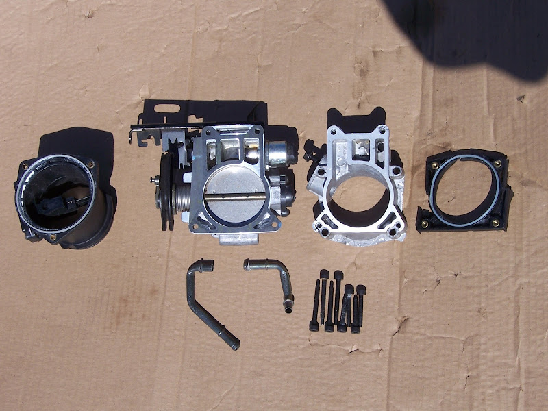
MAF housing, Throttle Body, TB Adapter, manifold flange. TB and MAF housing faces shown mate; Adapter and manifold flange faces shown mate.
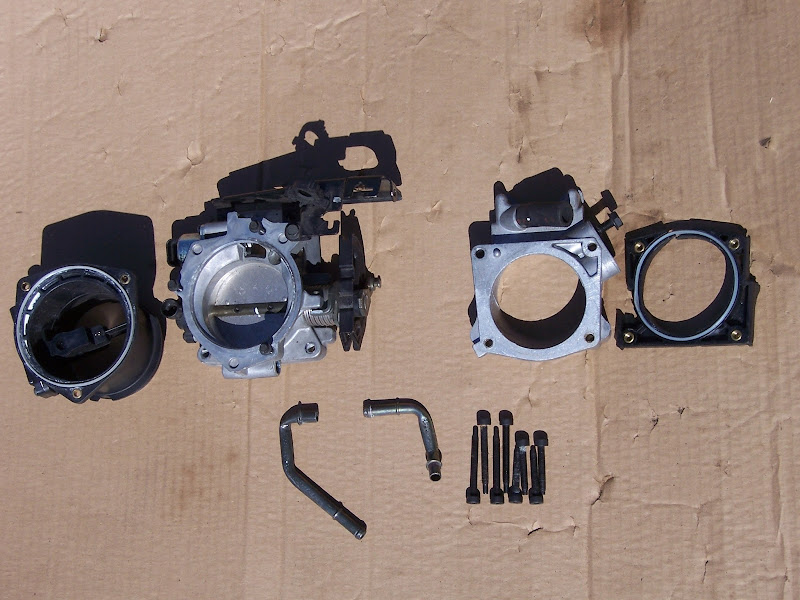
Old assembly vs. new parts. My high tech EGR blockoff plate is visible on the old TB adapter. It had to be modified slightly to work with the new hottness.

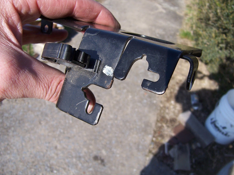
Throttle cable bracket... will take a pic of how I modded it sometime.
Full set of components that went through Liberty's Cryo+mikronite-like process: Getrag 3.94 R&P; Type II IMS; couple of extra CV joint cups (I think these were cryo only); side gears, spider gears and cross pin from the later style larger Getrag diff; spring plates from an EP LSD for same.
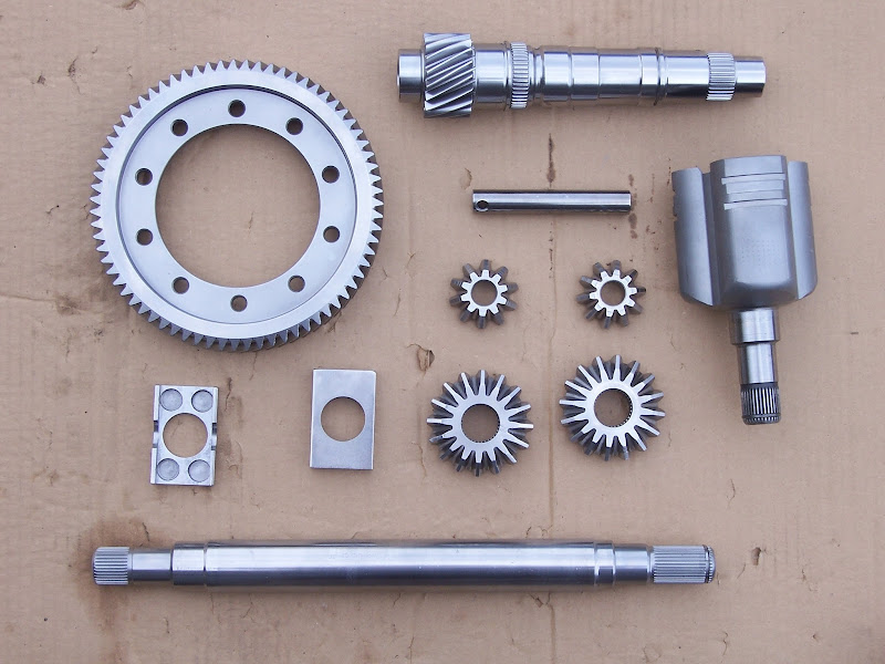
3.94 output shaft... hardness testing marks are *just* barely visible
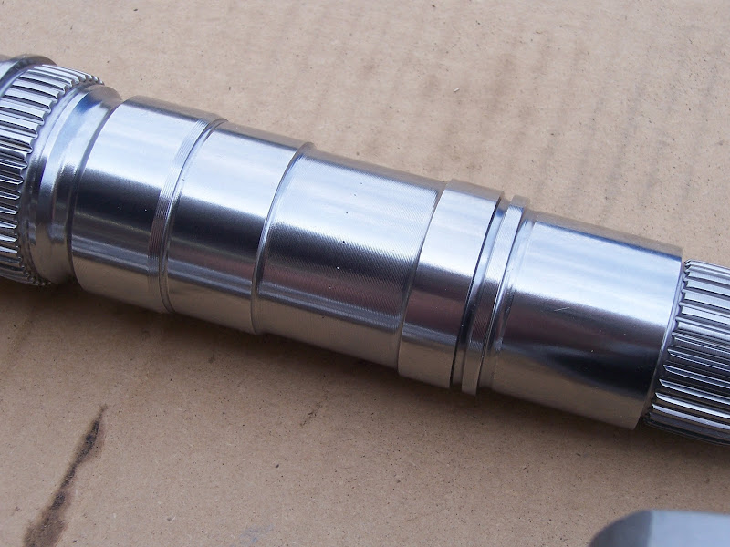
3.94 output shaft gear teeth and 1-2 synchro splines. Blingin'

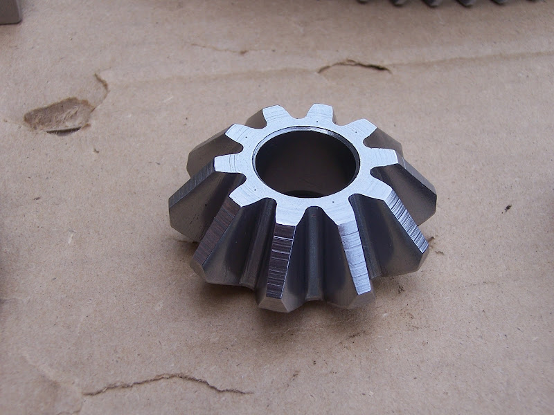
One of the spider gears, also with hardness testing marks visible
Transmission end of Type II IMS

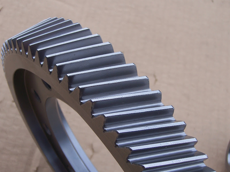
3.94 ring gear. It also has hardness testing marks on the ends of some of the teeth, but those aren't visible in this angle/lighting.
|
|
|
|
Will
|
APR 15, 12:07 PM
|
|
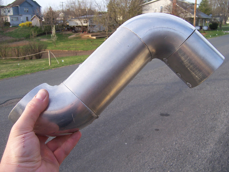
Made some progress on the intake tube: 3.5" aluminum tubing. The bends are from tight radius 3.5" donut halves that I had to order from F@#$ing Australia. The straight sections were rolled by a local sheet metal shop.
|
|
|
|
Will
|
APR 23, 04:32 PM
|
|
It's a graph. It has numbers. It scanned crooked because it was printed crooked.
I'm not sure what was done between the 306 ftlbs run and the 301 ftlbs runs. I hope that will be straighten-outable on my return to the dyno. I'd also like to get him to do some work between 1000 and 2500 RPM, as that's where I do most of my driving, and it's still a bit lumpy in that range.
Also need to be sure the tuner looks at peak injector duty cycle, so I know how much horsepower head room I have before I have to start looking for injectors.

This was Tuesday of last week. The tuner had problems with KR because I had a brain fart and still had the OBDI knock sensor, even though I'd switched to the OBDII PCM. I bought a new sensor and pigtail from CarQuest and installed that sensor late last week.
When I first assembled the engine, I used new valve cover seals. I did not have any problems with leaks. I took the valve covers off to re-torque the head studs and forgot that the seals are one-time-use. I reassembled with the old seals (because I had to move the car) and both covers leaked. I replaced them both again; the rear cover sealed up, but the front one still leaked. Just last weekend, I replaced the front seal AGAIN, and it finally seems to be sealed.
I have ordered a PCM bracket.
I need to measure the available space inside the quarter panel so I know which K&N to order. When I have the filter, I can finish the intake tube. Once that's done, I'll go back to the dyno for a touch up.
|
|
|
|
IXSLR8
|
MAY 01, 02:26 AM
|
|
|
|
|
Will
|
MAY 05, 01:28 PM
|
|
Thanks. I'm just getting started. ;-)
I have just a few more things to do to it, and then plan to leave it alone over the summer. I'll try to take it to the Texas Mile in October, followed by a round of engine-out mods.
A few more things to do:
-Mount PCM
-Complete intake tube
-Retune
-Spherical bearing suspension pivots
-Install treated axle components
-Complete/install oil pan heat shield
-Design/install oil/water heat exchanger
Hoping for ~320 RWHP at this point
Engine-out mods:
-Install 3.94 ring & pinion with EP LSD.
-Install worked crank with corrected rod journal diameter and rod bearing clearance
-Install ported heads
-Install Y2K+ intake manifold
-Install 266 intake cams in exhaust locations
-Rework wiring harness and find permanent home for PCM
-Remove stock oil fill, install new oil fill and paint valve covers
-Repair/replace right decklid hinge box and chassis side dogbone mount bracket
-Chromoly flywheel?
Hoping for 360 WHP and will turn 7500 RPM at this point
Afterward:
-Headers
-288 reground cams
-Throttle per cylinder
-Even bigger cams from custom billets?
-Franken F40 with '07 first-fifth, 0.62 sixth and 3.91 final
Final goal: 450+ RWHP and 8500 RPM[This message has been edited by Will (edited 05-10-2013).]
|
|
|
|

