|
| Trinten's SBC/F23 build - The work has begun! (Page 75/76) |

|
Trinten
|
JUL 22, 01:19 PM
|
|
That would be a 'Mike' question.
I know he referred to the cam spec sheet when we were first setting things up, and in the colder months when we could do drive-and-tune, he would be working in both the Spark Advance table and the Base VE table, seeing what the A/F ratio was, RPMs, engine responsiveness, etc. Though that was at side-street speeds and highway speeds (to a much lesser extent... except for last November when it was nice and cold and we put a solid 90 minutes of highway miles on it).
This is part of why I bought the thermal camera, so we can check out stuff like that and see how hot things are getting.
We can certainly play with the timing and the VE table. Right now it likes to be a little on the rich side during a cold start. Maybe if the timing was slightly advanced at lower RPMs, it wouldn't need to be so rich. I won't be out at Mike's this weekend. Next time I'm out there, I'll ask him. It can't hurt!
|
|
|
|
fieroguru
|
JUL 22, 06:24 PM
|
|
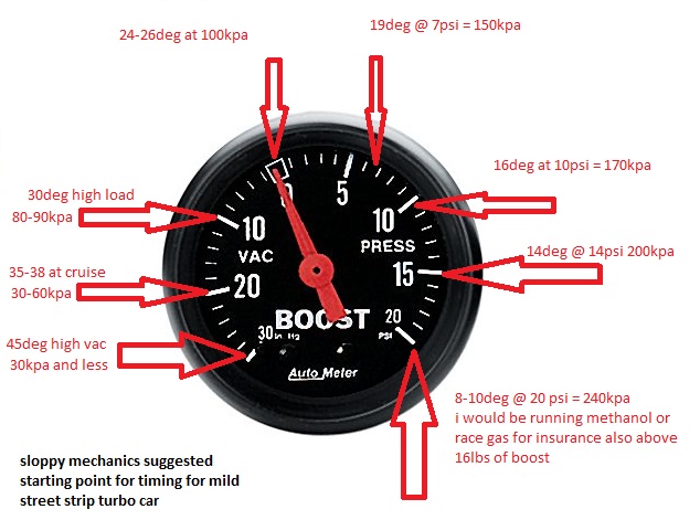
Vince, here are some timing maps I have used on my LS4.
This was the E67 naturally aspirated tune that was dyno'd. The cam was a 224-232 cam, which is a smaller than yours. The highlighed row is bacially WOT (100 kpa) and the lowest value is idle. It uses RPM and Cylinder Airmass, vs. KPA so it might not be easy to convert.

Here is the one I am currently running on my LS4 Turbo with the 219/223 cam (much smaller than yours). Dont be afraid to have 40+ degrees in the cruise areas.

Here is the idle timing:

When my car is at a hot idle @ 850 rpm, the timing is about 18-19 degrees.
Base maps on aftermarket ecms can be total garbage if they haven't done a lot of R&D for that application.
|
|
|
|
Trinten
|
JUL 30, 12:35 AM
|
|
Thanks Paul, apologies for the delay in posting.
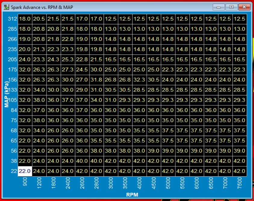
Is the "base ignition angle" in the second picture the same as the base volumetric efficiency table?
If so, my table is drastically different from yours (besides the layout being inverted).
I also tried to do some spot conversions for your spark table from (g) to kpa... I was not doing it right, the numbers it was spitting out when I converted mine to (g) were too far different to be plausible. Here's the two tables.
First up, my spark table.
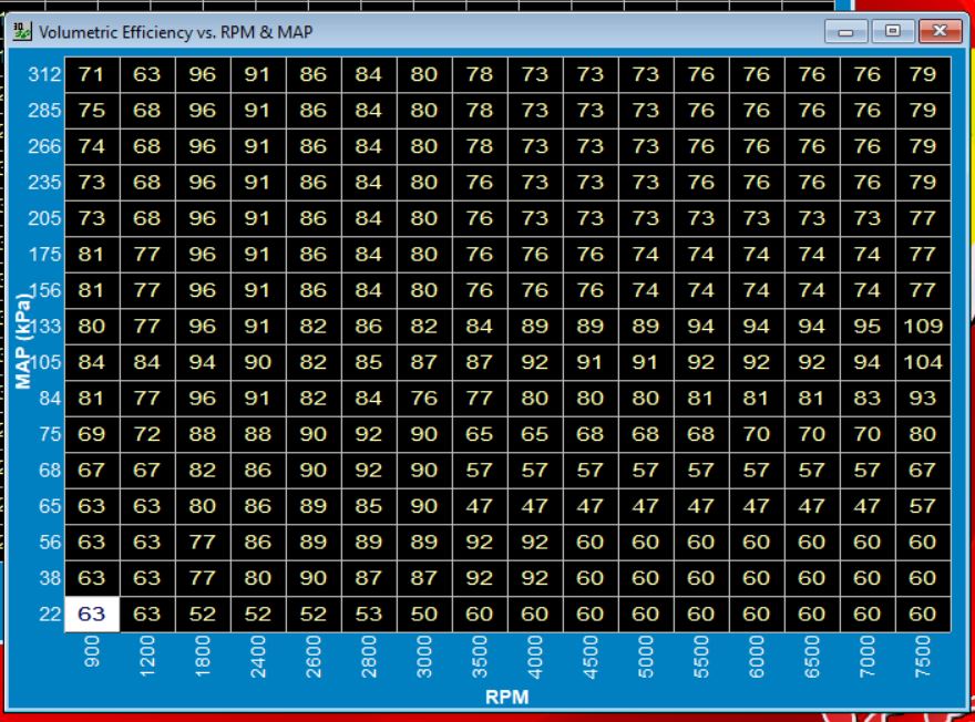
And here is my Base VE table.
I don't seem to have a setting anywhere specifically for idle timing. My Idle specific options are:
Throttle Follower
Idle Speed vs Coolant Temp
Start IAC Position vs Coolant Temp
Timing Trim (which brings up a Spark Offset vs. Idle Speed graph where I can adjust the relationship curve)
and Idle Parameters (IAC 'P' Gain, IA 'D' Gain, Max TPS for Idle (%), AC Idle Increase (RPM).
|
|
|
|
fieroguru
|
JUL 30, 07:13 AM
|
|
|
|
|
Trinten
|
JUL 30, 02:18 PM
|
|
Thank you!
The file we started with was an LS file that came with the FAST software. You are correct that there has been a lot of tweaking done by Mike when we would drive it around, including when he'd have me go to (or near) WOT.
The idle right now is 1100 to 1150. That is up from where it was in April, when I started messing around with the start-up tune. I made very small changes to the VE table (I would have to compare file versions to remember what they were, thankfully I save things with a date tag). Most of the change was with the throttle blade screw and TPS relearns. I opened it about 0.5 a turn.
There is also an after start table (in graph form) for Cranking Fuel vs. Coolant Temperature that I had tweaked.
Prior to making the tweaks above, the car would start with a fraction of a pedal press (basically starting around 1100-1200 RPM), and you had to keep it there for about 30 seconds before letting off the pedal, or it'd stumble and die.
I've tried adjusting the start IAC vs Coolant temp graph, but anything other than "wide open all the time" made the engine very difficult to start, even when reducing the fuel.
FAST also has After Start tables and other Spark modifier tables (like Spark offset vs. Fuel Energy Constant / vs. Inlet Air temp, / vs. Coolant temp) that I've tried doing adjustments to, testing, and if it didn't improve anything I put it back. I don't have the knowledge to confidently say "oh, if I change this on Table A, I need to also change variables on these other three tables to truly know if this helped".
I am learning, but have a way to go. Mike has shown me stuff by using his Grand National as an example. He'll change something in one table, the engine runs worse, then he shows me why based on an input from another table. It's a lot to try to take in and retain when you're only messing with it like, once a month (if that).
I will knock down the VE values in the area where my 'idle bubble' usually sits. Regarding it being aggressive under boost, the concern is knock? Right now we are running 92/93 octane, we haven't had any knock issues, thankfully.
|
|

|
Trinten
|
AUG 02, 10:44 PM
|
|
Well... I am having some buyers remorse.
I made it out to Mike's today, FieroGuru's tables in hand, and was like "hey, why did we retard the timing so much?" and he was really good about refreshing my memory "remember the surging issue we had because of the cam size? That's why." "Crap." then we got into why I asked, showed him FieroGuru's posts and such and he goes "Yeah, a smaller cam would play nicer, I told you we could switch out if you wanted to, and he's right there's a lot of other areas we need to put more time in."
So then he goes "I have something else about the cooling we need to check. I started the car up and was checking out the fan. It's only blowing air in a very narrow 'band', it's not pushing air the whole length of the blades to the hub, and the air isn't very hot. You put your hand behind the stock fan in my Fiero or GN, and it's HOT air. The GN fan is pushing more than the Fiero fan, but they're both pushing more, and it's hot. I want to put one of my extra GN fans on this today and see what happens."
"Umm. The GN fan is going to be too wide, I think." "We'll see." so he gets one - and it was too wide to mount normally, but putting it horizontally resulted in a pretty close fit with this radiator. The shroud at the bottom had a gap about 1/8" of an inch. This fan also has two bolts it uses to connect wires (which is wild to me), so we're going to do it quick and dirty, and hook it right to the battery. He gets everything ready, has me start it and tell him when the coolant hits 190. I do. He connects the ground, fan kicks on.... a minute passes, temp creeps up a little more... a little more, we get to 198... then it starts to drop.
Temp creeps down to 186, sometimes hovering back up to 188. So he unhooks the ground and tells me to let him know when it hits 210. It slowly climbed and went from 209 to 211. I tell him it hit, he hooks the ground, and for the first minute the temp still climbed, it got up to 218, then started to drop down again, getting down to 206-208.
So he said "we need to figure out how to make a good type of shroud and fit this fan in here." and I said "wait, this is a stock GN fan. Aren't these getting tough to find?" and he conceded "Well, it's not super easy to find them in good shape anymore." and I said "Okay, I don't want to carve up one of your GN fans. Let me get in touch with Delta and see what they say."
So tonight I did email them, let them know what was going on and that we had video and pictures showing the ineffectiveness of their fan compared to a stock fan from the 1980s, and I asked if they would be willing to look at it - maybe there's a defect that was missed and they can fix it. If not, or if no defect is found, I asked if it was still returnable (Their website simply says returns have a 20% restocking fee, nothing about how long or if it was used or not).
If they can't find an issue and won't let me do a return... well... at least I guess I have a nice PWM to control something in the future based on temperature.
I also asked him if one of his buddies (guy owns a commercial overhead door fabricating company) if they could mock up more of the shrouds my radiator came with, so we'd have a few to cut up to mount other fan options. He said they probably could. In the meantime, I need to see if I can find out how much CFM that GN stock fan pushes (or buy one of those cool CFM measuring devices), and start looking at other fan options... again.
OH!! Last big thing. He pointed out to me how when the coolant is cold, the pump is partially collapsing the rubber supply hose at the radiator. So he wants to go ahead and bump up the bungs at the 1.25" coolant pipes to -20s, and put a Y fitting that is -20 to two -16s, and run dual -16 hoses to and from the water manifold (it has the hookups to support it). He wants to see if improving flow efficiency is going to help first.
So, I get to order more AN stuff. lol I need to buy stock in Fragola and Vibrant.
Mike is taking one of his turbo buicks to Drag Week in Detroit next weekend, and something else the weekend after that,, so the next update is at least a few weeks out.
Thank you kind readers for sitting through another novella post. I do have some pics and video of the temperature tome foolery today, if anyone is seriously interested I can upload them.
|
|
|
|
La fiera
|
AUG 11, 05:36 PM
|
|
|
Nice! Make sure you do the same test under load. Dropping temperature at idle is not the same as if the engine is being boosted under 75-100% load, at these loads the amount of heat increases exponentially. Is there any way that the fan can be programed to come on at say 210F at idle or below 60% engine load and as the load past 65% then the fan kicks in earlier; Something like 185F? That way the cooling system gets a head start on dissipating heat as the load/heat increases. [This message has been edited by La fiera (edited 08-11-2025).]
|
|
|
|
Trinten
|
AUG 23, 11:34 PM
|
|
| quote | Originally posted by La fiera:
Nice! Make sure you do the same test under load. Dropping temperature at idle is not the same as if the engine is being boosted under 75-100% load, at these loads the amount of heat increases exponentially. Is there any way that the fan can be programed to come on at say 210F at idle or below 60% engine load and as the load past 65% then the fan kicks in earlier; Something like 185F? That way the cooling system gets a head start on dissipating heat as the load/heat increases.
|
|
The controller the fan comes with lets you set two points, triggered by coolant temperature, and for each point you can set the fan intensity.
Delta PAG has been really good with working with me since I reached out to them with my concerns. The guy didn't try to do any blaming, he was really good about asking clear questions about the setup and being clear on why (and I get it, with the wiring harness they provide, the instructions clearly point out damage and problems that can happen if you hook things up incorrectly - the harness has wires that aren't use in every configuration).
He was also asking some of the same questions that were asked here, about the difference in temp between the two sensors, where they were and so on. He did ask what the coolant temp was on the inlet hose and immediately on the outlet hose. Which I didn't have yet (and forgot to get today. D'oh! ).
So they're showing a great willingness to work with me to try to get things right. So I'll continue to explore that soon (I have some trips coming up, I'll be traveling and putting discretionary funds into tthat).
I *thought* I had started another thread where I was asking questions on the instrument cluster and issues I had when bench testing the coolant gauge... but I can't seem to find the thread. So either I decided not to post it after typing it up, or it didn't post and I didn't notice it. Mentioning that in case someone finds my insane rambling where I'm wondering if the wiring diagram I had was wrong.
So Mike had put a two wire coolant temp sensor he had laying around (For a Grand National, of course) into the water manifold, and we had tried wiring it up to the coolant gauge, and it hadn't worked before. Thinking we had things right with the wiring (I probably was NOT on the right pin or something), I swapped out the IC (the one that came in this car originally was in rougher shape than my old one, so it worked out).
Today we were trying to figure out which wire in the trunk ran to that gauge. So at the IC, the wire is light green. But in the trunk... it's a different color green. Mike Ohm'd it out to find the right wire, and he wired it up.
Here's where it got odd. As the needle moved (yay!) I noticed it was off from what FAST was seeing. So he checked the ground wire he had temporarily connected. Asked me if anything changed. I told him no. He takes the ground off completely, asks me if it changed. I said "nope, still slowly climbing". We both thought for sure this sensor needed to a ground to work, and that once we pulled the ground, the needle would have either dropped back to 'cold' or pegged out. Neither happened.
We did realize later the temp difference was because that GN sensor uses a different Ohm range, so I need to get a Fiero one. Which is also two pin. So does anyone have any theories on why the gauge continued to worked properly after he disconnected the ground from the temporary sensor?
We also mounted the oil pressure sensor that will go to the Fiero gauge. We used the 88 sender, Standard Motor Products PS262. GM Part number 1808A. Putting the part numbers here because "sender" and "switch" are interchangeably used by various retailers for this part, and I have bought the wrong thing.
We didn't have time to wire up the oil pressure gauge today, so that will be next time. The new little length of hose and t-fitting Mike used (tapping into the line that feeds the turbo) didn't leak, which was great.
Even though the color scheme of the AN fittings is thrown off (there's now a stainless one in there, along with a blue "T" AN fitting, and mismatching hose segments), I might just leave it as a "last of list" item. It's not leaking. So if it works and is accurate when we get it hooked up... it can stay that way for now. lol. Too many times Mike will clean something up and get it all nice and sorted away, then something happens that makes us need to change it or things around it.
Next weekend I might see if he's up for getting the wiring from the FAST over to the IC Speedometer to get that working. I'm not worried about the Tach right now. Just be nice to have "the basics" (voltage, coolant temp, oil pressure, and speed) all working so I don't need to look at the FAST screen, which is not mounted in an ideal spot for the driver.
|
|
|
|
fieroguru
|
AUG 24, 09:33 AM
|
|
| quote | Originally posted by Trinten:
Which is also two pin. So does anyone have any theories on why the gauge continued to worked properly after he disconnected the ground from the temporary sensor?
|
|
The Fiero 2-pin temp sender for the gauges uses 1 wire for the gauge and 1 wire for the light. It grounds through the engine block to the chassis and back to the cluster.
The separate Fiero ECT sensor for the ECM is also 2-pin and grounded with a wire.
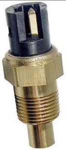
For the LS swaps, I use a 1998 Camaro LS1 3 wire coolant sensor in the head. It is a factory sensor with 2 wires for the ECM ECT and 1 analog wire to run the gauge on the dash (I don't worry about the light). It also has metric threads and is installed in the factory location in the head. https://www.amazon.com/Stan...oolant/dp/B000C81ZCM
| quote | Originally posted by Trinten:
We also mounted the oil pressure sensor that will go to the Fiero gauge. We used the 88 sender, Standard Motor Products PS262. GM Part number 1808A. Putting the part numbers here because "sender" and "switch" are interchangeably used by various retailers for this part, and I have bought the wrong thing.
We didn't have time to wire up the oil pressure gauge today, so that will be next time. |
|
The oil pressure sender is a 3-wire setup with the two side wires being a N.O. pressure switch, and the center wire being for the gauge. It also is grounded through the block with only 1 wire going to the gauges. You do not need to worry about the switch capability as it isn't used with your current wiring.
| quote | Originally posted by Trinten:
Next weekend I might see if he's up for getting the wiring from the FAST over to the IC Speedometer to get that working. I'm not worried about the Tach right now. Just be nice to have "the basics" (voltage, coolant temp, oil pressure, and speed) all working so I don't need to look at the FAST screen, which is not mounted in an ideal spot for the driver. |
|
If you plan on driving the Fiero speedo from the FAST ECM, then you will likely need to wire up this circuit to create the needed signal for the Fiero speedometer. You can also buy one here:
https://reddevilriver.com/h...peedo-buffer-circuit

For the tach, you likely will need to get 2 things:
1. New tach board - yours is likely old and not reading right, and is calibrated for a V6 and not a V8:
https://www.ebay.com/itm/14...Od%2Fj1MsH1w0hJhWlze gy9uz9PpQYc91mTxkHVzBaSix1TLxakBF0JiAXqbhWlYxq1c3VIeJt9%2FY12Uk5pgNrj2ZlUW4gX%2Bw67C%2FqF3chVBZWADfPMjLD%2FI3LsaoF024id1owExAFBNdb7KJLkHwT%2F4cD7OSvaOgHxbN3Jjs401IlTkvYcyvi57yh4nTxgHlA%2FVotnPhuhGNGGoYc%3D%7Ctkp%3ABk9SR5y_mMSbZg
2. You likely will need to wire in this circuit. It is OK to try it w/o first, but if it doesn't work try this:

|
|
|
|
Trinten
|
AUG 24, 11:48 PM
|
|
Thank you!
Okay, so his sensor might have worked because - if I understand things right, it doesn't need the ground except to kick on the warning light?
The FAST temp sensor we have in the head is kind of a pain to get to, and having a third point to see temp / temp differences at various points is not a bad thing. I will get that Camaro one. I'm glad you told me that the Fiero's had two various coolant sensors! With my luck I would have wound up grabbing the wrong one. And now that you mention it and put up that picture... I am positive I bought one of those, because the PICO connector for it took forever to show up. I need to find that and let you know the part number to see if it's one I can use.
If we go with the Camaro unit, which pin is the correct one for the gauge? (thank you for the link to the right part!!)
For the speedometer, I have the FAST software set to do an output at 4k PPM for the gauge. What is the function of the circuit?
I see on Red Devil's site, the description is "Fiero 3800 Speedo Buffer Circuit. Used in Fiero Engine swaps. Allows PCM speedo output to be interfaced with the stock Fiero Speedometer." this doesn't explain if it's adjusting things to be 4k PPM, or doing something else?
|
|
|
|