
 
     |
| LS4 / F40 swap - fieroguru (Page 7/216) |

|
fieroguru
|
JAN 03, 03:34 PM
|
|
Well my daily driver truck started to act up and wouldn't start, so I spent the better part of my New Years holiday working on it. Once it was running again, I was in the mood for some inspirational pics and needed to finalize the engine placement anyway... so back in the mockup chassis the engine/tranny/cradle went:
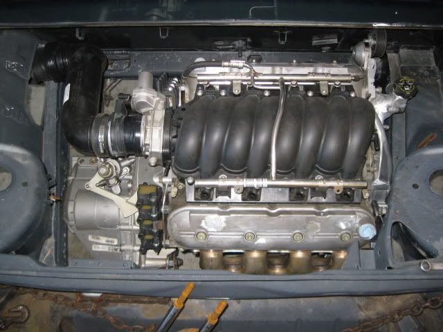
I went ahead and taped the 85mm MAF on the end of the throttle body and mocked up the air intake tube. This is the same GM plastic tube Darth Fiero uses on his 3800SC swaps. It need to be sectioned in the center to shorten it and then I can use some of the material to space the MAF from the throttle body and get the front/back portion of the intake tube to be closer to the driver side frame rail. If I can not get this plastic tube to work, I will just get some 3 1/2" mandrel bends and weld something together.
Here is the new thermostat housing and coolant fill location. The hose from this will easily clear the belt and the passenger frame rail.
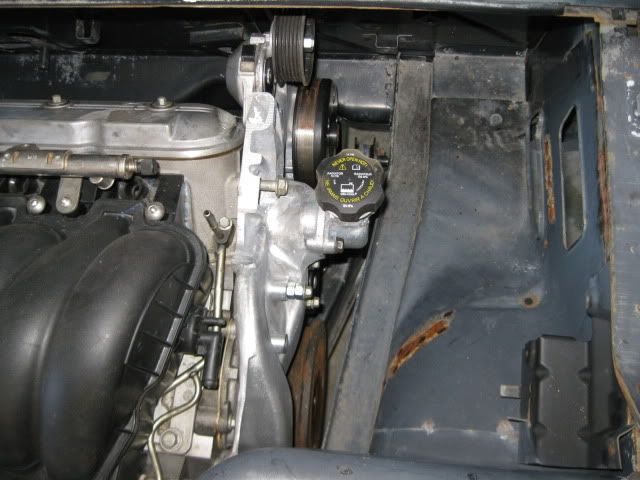
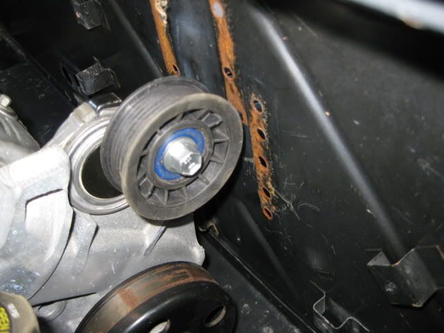
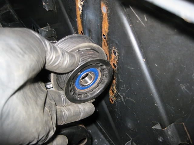
The tensioner pulley is about 5/8" from the firewall and only gets about 1/8" closer when the tensioner is pulled down. The vast majority of the engine movement will be to the rear, so this should be plenty of clearance. I could always swap out the pulley on the tensioner for the stock LS4 tensioner pulley that is about 1/2" smaller in diameter to gain some more clearance. Also, it is clear than the tensioner pulley will be into the passenger hinge box... it is good than my fiero will not need/have these boxes... mostly in an efffort to remove clutter from the engine bay.
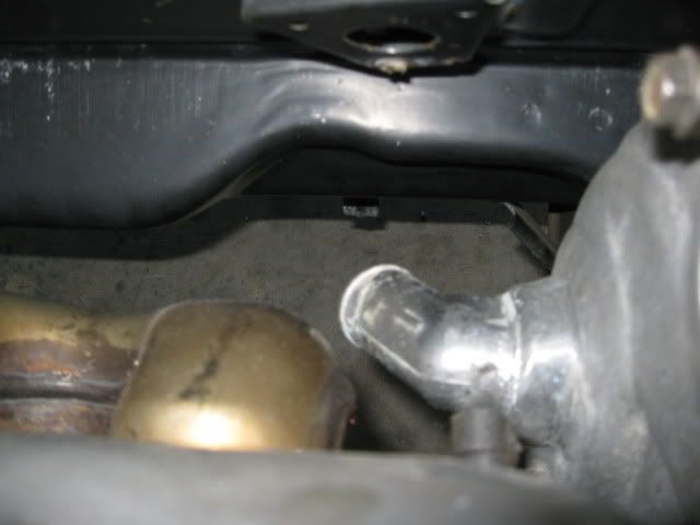
The coolant inlet on the back side of the water pump will clear everything and have the hose routed down by the recessed portion of the double firewall panel:
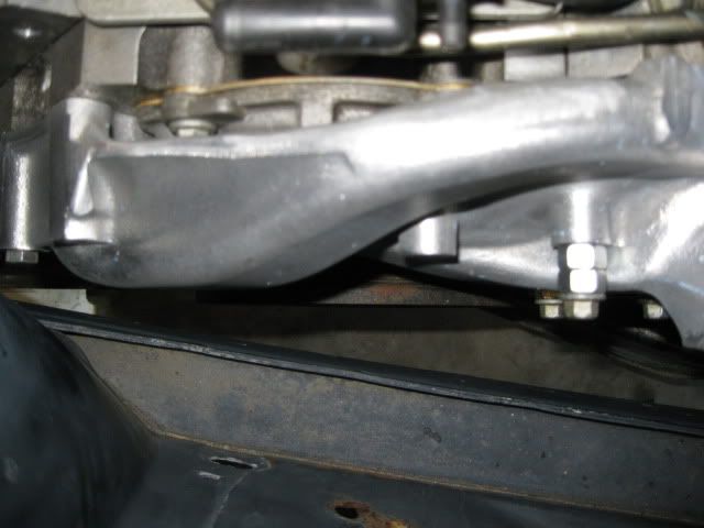
Water pump cleatance to the passenger frame rail... lots of room here:
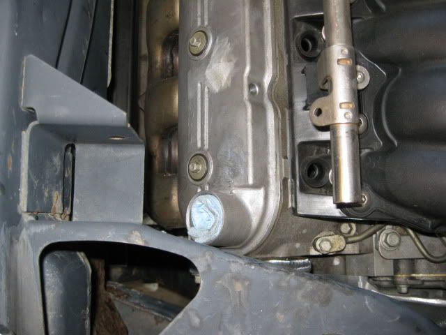
Oil fill is still trying to co-exist with the dogbone bracket. My fiero will not have this dogbone bracket to contend with.
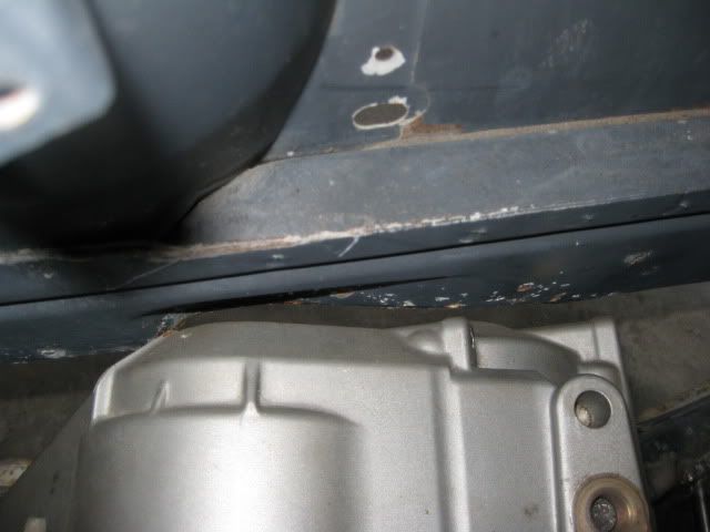
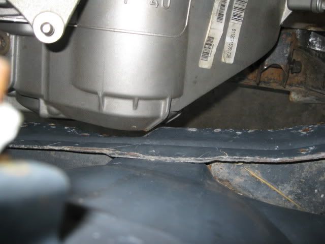
F40 transmission to the driver side frame rail has about 1/4" clearance to the factory notch in the frame. I am seriously considering moving this factory notch to the rear 1" so it is better positioned around the F40 and will give it more room. I am not a fan of frame modifications, but the clearance in this area will be visible and I want it to look good. Right now the notch isn't centered and the tranny is very close to the edge of the notch... it would look better with the notch moved to the rear 1".
Here is another overall picture before I mocked up the air intake tube.
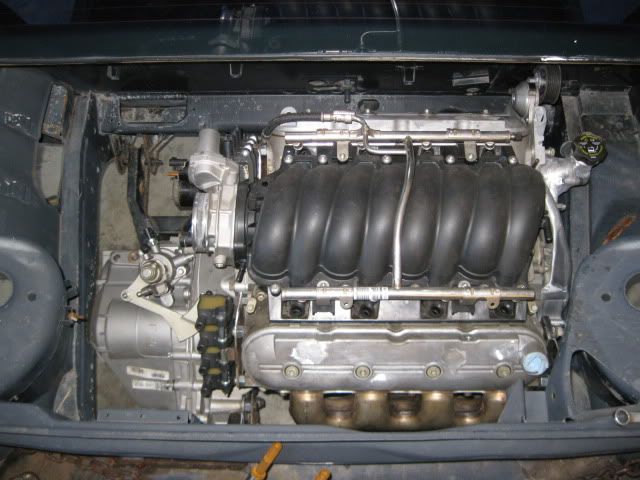
Now I can finish up the mount tabs and have the engine/tranny fully mounted to the cradle.
|
|
|
|
qwikgta
|
JAN 04, 04:44 PM
|
|
looking sweet. looking forward to the updates and pics.
edit - what plug wires are you going to use? have you looked for them yet?
Rob
------------------
88 Coupe, CJB T-TOP, LS376 and a GT clip[This message has been edited by qwikgta (edited 01-04-2011).]
|
|
|
|
stickpony
|
JAN 04, 06:12 PM
|
|
| quote | Originally posted by fieroguru:
Here is another overall picture before I mocked up the air intake tube.
Now I can finish up the mount tabs and have the engine/tranny fully mounted to the cradle. |
|
hey Fieroguru...
had an F40 tranny questions for you: a master fabricator such as yourself might be motivated to alter the gearing of the F40, since 1st gear is so intolerable for a powerful V8 such as the LS4. i would think that someone such as yourself might want to do that.
as it sits, the 1st gear(3.77:1) combined with the final drive(3.55:1) gives a combined ratio of 13.38:1. that is outrageous behind a v8 man! you would be shifting after barely touching the gas...with the average fiero tire size, you would be shifting around 25 mph....dropping both the 1st gear and the final drive to something around 3:0:1 would of course be ideal
so is this something that is doable??[This message has been edited by stickpony (edited 01-04-2011).]
|
|
|
|
fieroguru
|
JAN 04, 06:18 PM
|
|
| quote | Originally posted by qwikgta:
looking sweet. looking forward to the updates and pics.
edit - what plug wires are you going to use? have you looked for them yet?
Rob
|
|
I have been checking around for options and found where several people were using the LT1 optispark wires. I prefer to get the cut to fit versions so I can make the routing clean. I am kicking around running the wires in a square bundle of 4 vs. a stacked set of 4... Might even run the wires in aluminum or stainless steel tubing (non-polished)...
|
|
|
|
fieroguru
|
JAN 04, 06:42 PM
|
|
| quote | Originally posted by stickpony:
hey Fieroguru...
had an F40 tranny questions for you: a master fabricator such as yourself might be motivated to alter the gearing of the F40, since 1st gear is so intolerable for a powerful V8 such as the LS4. i would think that someone such as yourself might want to do that.
as it sits, the 1st gear(3.77:1) combined with the final drive(3.55:1) gives a combined ratio of 13.38:1. that is outrageous behind a v8 man! you would be shifting after barely touching the gas...with the average fiero tire size, you would be shifting around 25 mph....dropping both the 1st gear and the final drive to something around 3:0:1 would of course be ideal
so is this something that is doable??
|
|
I haven't taken either of my F40's apart to see how difficult the change would be. If all the gears are seperate and not integrated into the shafts, then it would be much easier. I would love to have either a 3.0 final drive or a 3.0 first gear... but either of those would probably double the cost of this swap, so I will be sticking with the stock ratios.
Knowing the ratios are what they are, my engine was built to rev and I am planning to shift at 7000 rpm. This makes 1st gear last till 38mph and 2nd till 71 with a 24.6" I could gain a few more MPH in each gear by going to a slightly larger diameter wheel/tire package.
|
|
|
|
RumbleB
|
JAN 06, 03:58 PM
|
|
You might have talked about this, in one of your other threads. But I am going to ask any how.
What kind of welder do you use? Just wanting to know how you are welding aluminium?
I have a mig welder that runs on 110 A.C. It does a lot of the work that I need done, but I don't think it will do aluminium
Don Z..
|
|
|
|
fieroguru
|
JAN 06, 04:23 PM
|
|
| quote | Originally posted by RumbleB:
You might have talked about this, in one of your other threads. But I am going to ask any how.
What kind of welder do you use? Just wanting to know how you are welding aluminium?
I have a mig welder that runs on 110 A.C. It does a lot of the work that I need done, but I don't think it will do aluminium
Don Z.. |
|
Lincoln ProMig 175 (from Lowes on clearance). It is a 220V welder and setup for shielding gas. I use Argon/CO2 mix for mild steel and 100% Argon for aluminum.
Many of the name brand mig welders have an aluminum conversion kit (about $65) that comes with a special liner, special feed wheels and tips. Once you have it, the welder settings are much more critical - it is VERY easy to deform the wire and cause it to kink/bind while feeding. It is also important to keep the lead as straight as possible to lessen the resistance to pushing the aluminum wire.
The melting point difference between aluminum and aluminum oxide (the outer layer) is around 300 degrees, so if you do not clean off all the aluminum oxide before welding, you will put too much heat into the material to melt the aluminum oxide and once through the base aluminum falls away.
It is also important to preheat the aluminum some. Aluminum disappates heat very quickly and if you do not preheat it, then you need to start out putting more heat into the weld and then back it off as the temperature of the part starts to increase.
A tig would be great...
|
|
|
|
JazzMan
|
JAN 06, 06:51 PM
|
|
I just finished the TIG course at my local college, it's the only way to go with aluminum. Aluminum welding with wire is really meant for large scale production environments. Besides the special hardware (I highly recommend a spool gun as you're pretty much certain to birds-nest aluminum trying to push it through a typical 10' torch lead) you must run a different gas, pure argon. Most all mild steel welding is done with C25, a mixture of 25% CO2 and 75% argon. Like Guru said, prep is critical as aluminum oxide forms almost instantly on freshly cleaned surfaces and not only inhibits welding but contaminates the weld as well. That's the other problem with welding with wire. Wire machines are DC, which means the welding current flows only one way. TIG machines when used to weld Al are setup as AC; the reversing current cleans the oxide layer (the one you can't see that formed immediately after cleaning with a brush) and makes welding oh so much nicer.
I was going to get a spool gun for my Miller ($900, ouch) but after taking the TIG course I'm going to stick with my EconoTIG, and keep my eye open for a nice Synchrowave like this one: http://dallas.craigslist.or.../tls/2109869452.html
|
|
|
|
fieroguru
|
JAN 06, 07:44 PM
|
|
| quote | Originally posted by JazzMan:
|
|
Glad to see you posting again!
|
|
|
|
RumbleB
|
JAN 06, 08:12 PM
|
|
|
Thanks Guys! I guess, I keep an eye out for a tig. My Miller 140 is gas shielding and does a great job for the most part. But I don't think it will do aluminium.
|
|
|
|