|
| LSJ Supercharged Ecotec Swap (Page 7/45) |

|
jmarek78
|
JUL 07, 02:34 AM
|
|
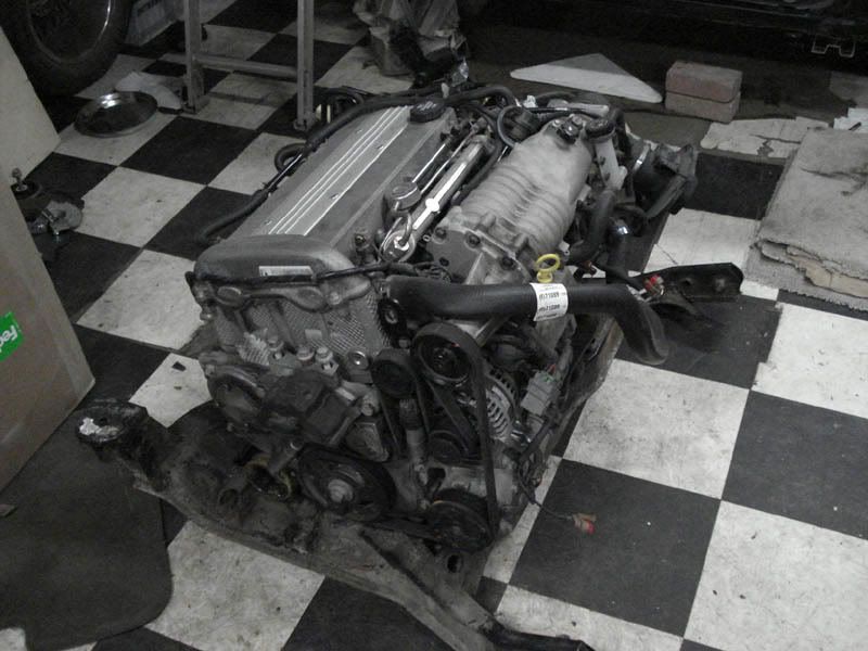
I can't believe I didn't notice this thread sooner... I've had my LSJ/F35 mocked up in the fiero cradle sitting on the floor for a good 4 months now. I tilted mine a little more than the cobalt setup to clear the cradle without any major cutting, and to keep the supercharger and the dipstick out from underneath the rear window. Then I bought a C4 and sorta lost interest in the fiero... but I'm going to start working on it again soon. Have you looked into fabricating the trans mounts yet? I've been thinking about modifying these mounts to fit the fiero: http://bwoodyperformance.co...th=23&products_id=55 ...The rear one should be real easy. The front will probably require me to cut into the cradle, but the cradle should be strengthened at that spot anyway to handle the torque load (I see you've got that covered already). The side mount will be easy to attach to the fiero frame rail and at that point my setup will be the same as what the cobalts are running, so I should be good to go.
I'm glad to see someone else is doing this so I can borrow some ideas 

|
|
|
|
ccfiero350
|
JUL 07, 11:07 AM
|
|
Glad to have you on board.
I'm in the process of fabbing the mounts now. In fact I scanned in the poster board templete of the front tranny last night. I do believe I will be replacing the rear cross member with another 2x3 tube. Very much like fieroguru"s here.

As you have observed the rear transmission mnt for the F35 is just too far away for my tastes, from the stock subframe mnt location. And the fact the original crossmember looks like hammered crap now anyway from all the jacks through the years.
Since this is going to be a track car, it will be thrashed on a regular basis and the subframe/engine mnts are to be made to stand the rigors of racing. ------------------
yellow 88 GT, not stock
white 88 notchie, 4 banger
|
|

|
Austrian Import
|
AUG 10, 04:52 PM
|
|
|
|
|
ccfiero350
|
AUG 11, 09:49 AM
|
|
After a long interuption of working for a living I'm back playing in the shop.
I have replaced the rear cross piece with a strait piece of 2x3 tube. Today I'm going to mockup the engine/cradle again and fab the fore and aft trans mounts. I'm photo documenting as I go and will post the images this weekend to get everybody caught up.------------------
yellow 88 GT, not stock
white 88 notchie, 4 banger
|
|
|
|
Austrian Import
|
AUG 25, 03:15 PM
|
|
it's the weekend.
*bump for updates*
|
|

|
ccfiero350
|
AUG 25, 10:41 PM
|
|
|
|
|
ccfiero350
|
AUG 25, 11:18 PM
|
|
|
|
|
Riceburner98
|
AUG 26, 10:43 AM
|
|
| quote | Originally posted by ccfiero350:
There could be a very cool little black box if somebodies good with PWM circuits.
Here's the goods to make the generator do its thing all the way.
The L-termanal control signal is a 5 Volt pulse with modulated (PWM) signal of 128Hz with a duty cycle of 0-100%. Normal duty cycle is 5-95%. The either extremes are for diagnostics purposes.
The following table shows command duty cycle and output voltage of generator.
0%______0V
10%_____11V
20%_____11.56V
30%_____12.12V
40%_____12.68V
50%_____13.25V
60%_____13.81V
70%_____14.37V
80%_____14.94V
90%_____15.5V
100%____13.8V
As you can see you could make a Dail-O-Voltage box with this data, if your real good with some programing you can combine timers with inputs so you boost idle voltage when the a/c comes on or just after it cranks for 20 seconds like the factory does.
Some stand alone efi controllors have programable PWM outputs just for stuff like this.
|
|
Any idea if the input to the alt. needs to supply any sort of current, or only a few mA? The last PWM box I made with a microcontroller was in the kHZ range, 128hZ should be easy to hit with plenty of processor power left over for checking inputs. If I ever get caught up with all the projects I'm working on I'll have to try this. I printed out the post as a reminder.  If anyone's built one already, feel free to let me know so I won't be duplicating work. If anyone's built one already, feel free to let me know so I won't be duplicating work.
|
|
|
|
ccfiero350
|
AUG 26, 11:05 AM
|
|
|
I don't know about the input impedance but it's a good bet if it's a 5V logic, it would be TTL. ------------------
yellow 88 GT, not stock
white 88 notchie, 4 banger
|
|
|
|
Austrian Import
|
AUG 29, 04:21 PM
|
|
Thanks for posting the pics. Really cool to see the progress. :-)
Would it be easier to use a non '88 cradle/Fiero, or would there be similar challenges involved in getting the engine mounted?
Would similar problems exist with the alternator when using the stock ECM? (Would have to anyways to make the car C.A.R.B. certified)
|
|
|