
 
     |
| ecotec swap (Page 68/98) |

|
wftb
|
JAN 26, 09:04 AM
|
|
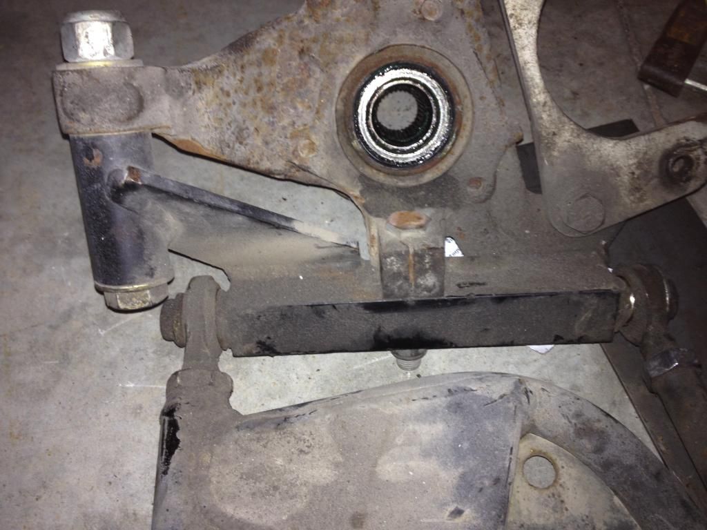
Looking at the bracket in the last picture , I just realized that using the strut bottom for the base of the bracket is not needed .Since the cam bolt adjustment does nothing any way , I can make a much nicer looking bracket without the remains of the strut in it .I can get all the dimensions I need off the existing bracket .
|
|
|
|
wftb
|
JAN 27, 11:45 PM
|
|
|
I have the outer delrin bushings in the machine shop getting the AL bits machined to fit in the DOM tubing I bought at a place called the Metal Supermarket down in Mississauga .Fun little place , great selection and they will sell you anywhere from 6" to 6 miles of just about anything metal .But I do not know if I will end up using the outboard bushings or not .Yarmouth fiero came up with a bracket idea to attach a tie rod to the lower control arm .It looks very simple to make and if I used it instead of a rigid upper control arm I would have more flexibility in control arm placement .With what I am trying to do now , to replicate the up and down motion and placement that the strut creates , I conclude that the arm could only be located in one place with the only variables being the height of the mount on the spindle stub and the upward or downward angle of the arms at ride height .Owing to the space limitations with my engine transaxle combination , the maximum length of the upper arms is 5.5" centre to centre .That is pretty short , but still workable .My wife has a car parked for the winter with a similar length upper rear control arm . Anyway ,if you imagine a line drawn between the ball joint and straight up to the top strut mount , you have a line that you could run an upper control arm at right angles to make something that would move the wheel up and down similar to what happens with the strut .Except that because you have now created an unequal length upper and lower control arm suspension ,it follows an ellipse rather than a straight line .The problems inherent in this design of mine are that if you look at the strut stub without the strut on , the line it follows appears to lean towards the front of the vehicle .So if you want anti squat , the angle of my arms is actually backwards . The other strange thing has to do with the angle deviation from longitudinal of the factory lower control arm mounting points vs the angle of my control arm inner mounting points .Keep in mind that for my upper arms to maintain the toe constant they have to be lineal and parallel to each other .So direction of the line drawn between the inner bushings of the upper control arms as designed compared to the line drawn between the inner lower factory bushings would form a shallow X rather than an 11 .So I don't think it would be possible to even use suspension software to predict how this would function because who would even think to design it that way ? But the thing is , doing stuff like this is my hobby .Just because it should not work , does not mean it wouldn't work .But if something easier comes along , who am I to flog a dead horse .I still would like to see how this setup would work , suspension design truly is more of a black art rather than pure science anyways , but I am going to change direction here .If I use Yarmouths neat little bracket ,I can use an upper ball joint instead of two bushings and I can angle the arm any way I want and I can make it parallel to the to the lower control arm mounts .And a bonus is that the bumpsteer arms have everything I need to finish the bracket .The trouble with using a spindle designed for a strut is that it has to move up and down in one angle .If you lever the stub fore and aft to change the arm angle , you just lengthened or shortened the cars wheelbase .And if you rotate the stub , you change the toe .It limits your options .So the next time I post , you will see something completely different .Might be a while .
|
|
|
|
wftb
|
FEB 02, 03:09 PM
|
|
I have been busy reading my suspension book and have established some basic dimensions and angles and a path forward .Looking at my old bumpsteer arms , not only can I salvage the parts needed to make a Yarmouthfiero bracket , the bracket itself can be made from a part of the arm .
 If you look at the square pivot bar that is bolted in where the lower ball joint should be , you can see that I can cut it to bolt to the ball joint pinch bolt and then cut the post that bolts to the tie rod arm a little shorter. Drill and tap the bar , get a shorter bolt for the tie rod arm and I will have my bump steer bracket . If you look at the square pivot bar that is bolted in where the lower ball joint should be , you can see that I can cut it to bolt to the ball joint pinch bolt and then cut the post that bolts to the tie rod arm a little shorter. Drill and tap the bar , get a shorter bolt for the tie rod arm and I will have my bump steer bracket .
|
|
|
|
wftb
|
FEB 04, 05:41 PM
|
|
I tried making a bracket out of the bumpsteer arm but that did not workout very well .That and the fact that the finished product was going to weigh over 5 pounds made me decide to attempt making one from scratch .It is a variation of what Yarmouth drew up .I have not carved it up to make the rod end mount yet .I need a ball joint to measure so I get the hole in the right spot and I don't want to mess up the ones on the arms now .CDN tire showed 0 stock in the warehouse so I will try one of the local parts guys on saturday .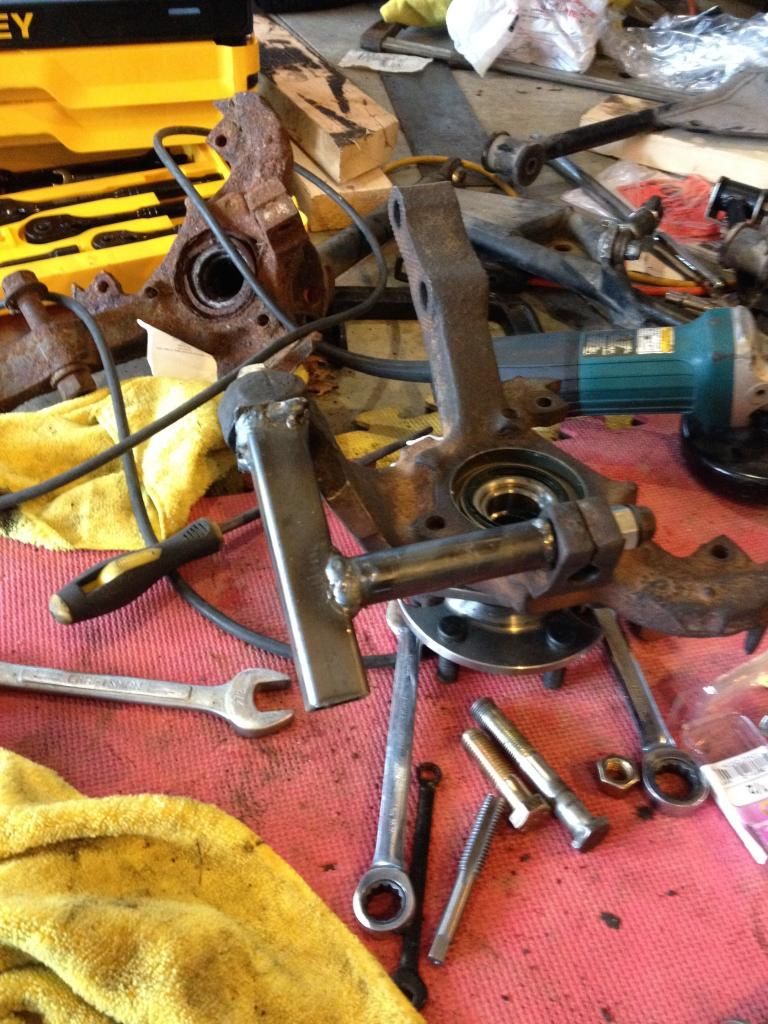 There is a corner gusset and a back side brace that will be added next time I get a chance to work on this . There is a corner gusset and a back side brace that will be added next time I get a chance to work on this .[This message has been edited by wftb (edited 02-05-2015).]
|
|
|
|
wftb
|
FEB 06, 10:18 PM
|
|
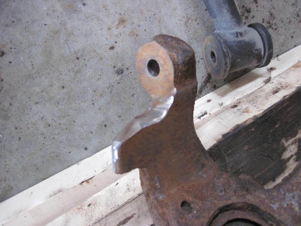
Got a little more done on the bumpsteer arm .I was looking at how I could brace it up some more , and I realized the spindle has sort of a natural brace built in to it :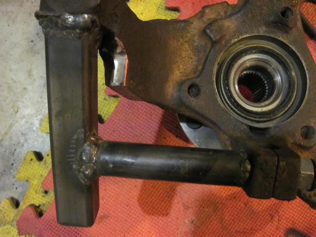
I ground a flat spot on the little wing (I think it was a steering limiter for the front of an X car , does nothing on the rear of a fiero ) The corner bracket butts up against this wing and that will prevent the brace from bending out .I have found that the spindle you are looking at is garbage .It looks like it was driven with a loose or broken cinch bolt and it is too sloppy to use .No matter how much I tighten the bolt , the ball joint stud stays sloppy .I traded member Lunatic 4 spindles for a GT wing and I found a better one that fits nice and tight .But now I have to change my new hub over to that spindle .On the bright side , I can do a better job of carving the wing to give better support for the brace .
|
|
|
|
wftb
|
FEB 06, 10:24 PM
|
|
Heres the angle bracket tacked in place :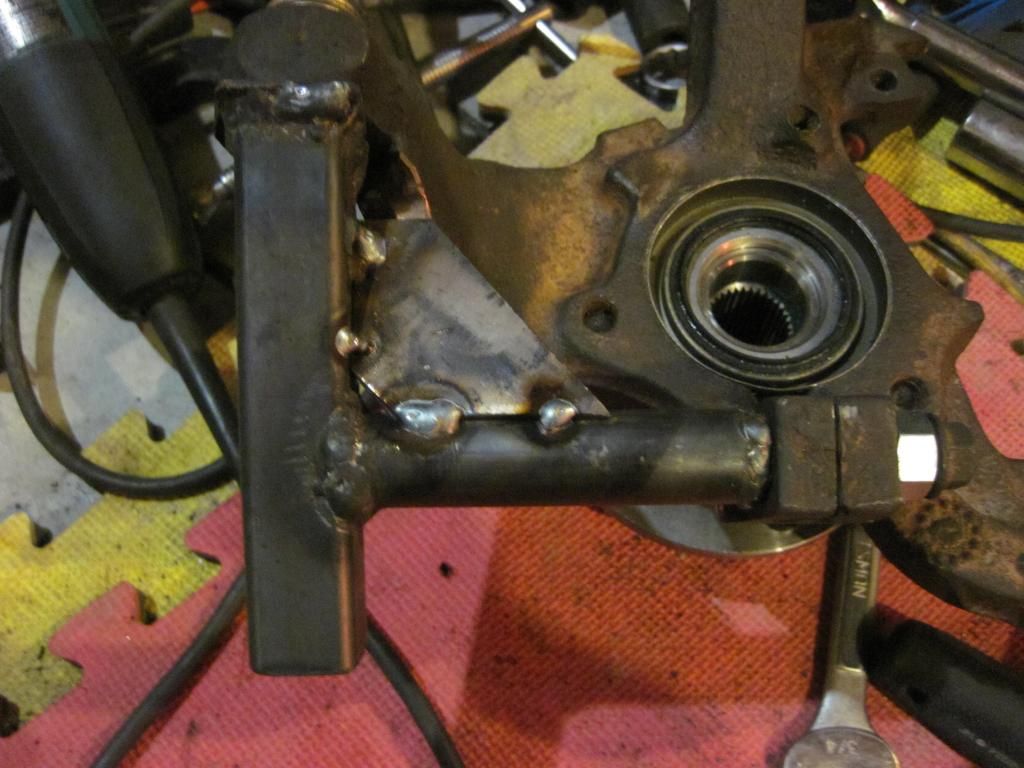
It is too dark in the garage at night to do a good job of the welding so I will finish it up tomorrow .
|
|
|
|
wftb
|
FEB 07, 12:03 PM
|
|
|
Now that I have been forced in to working with a bone stock spindle , I realize there are more ways to brace this piece than I first thought .If you leave the steering stop mostly as is and just grind off what you need to fit your brace in , you can drill and tap a hole and bolt directly to the spindle .I added another small brace and welded everything up and I think I have a mount that can not bend or twist now .
|
|
|
|
wftb
|
FEB 07, 12:08 PM
|
|
|
|
|
wftb
|
FEB 07, 12:13 PM
|
|
Grind the spindle steering stop:
|
|
|
|
wftb
|
FEB 07, 12:21 PM
|
|
Here is the other side of the brace all welded up . 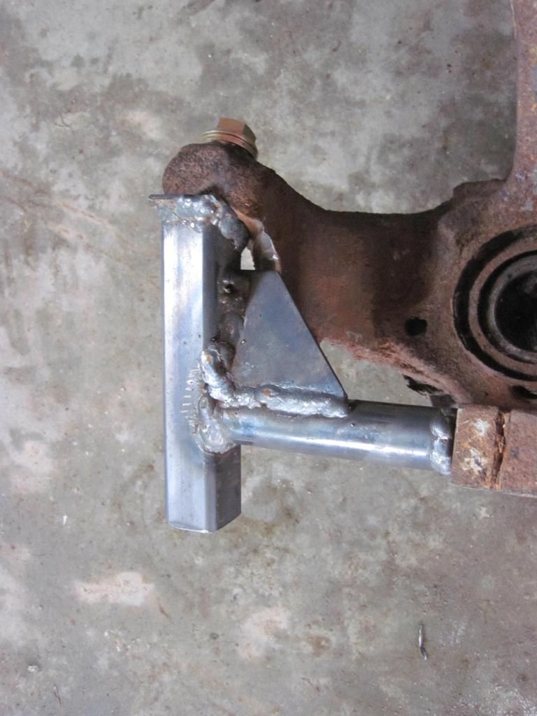
|
|
|
|


