
 
     |
| ecotec swap (Page 67/98) |

|
wftb
|
JAN 20, 10:33 PM
|
|
|
|
|
wftb
|
JAN 20, 10:48 PM
|
|
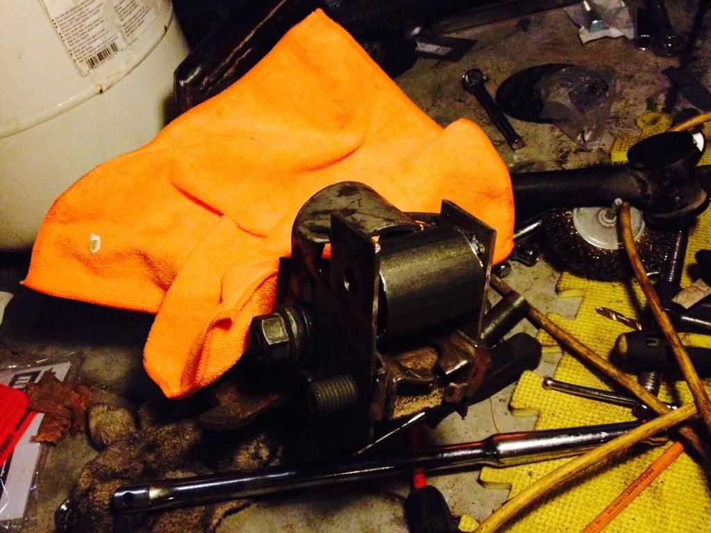
So this is what I did today .I cut off some metal of the former strut bottom so that i could mount the plates that you see .After the bolts were mounted as shown , I welded the flange nuts to the plates .Then I cut a piece of 1 1/2" pipe that will be welded in between the plates as a spreader .Another pipe stub mount will get welded on both sides to hold the arms to the spindle .[This message has been edited by wftb (edited 01-21-2015).]
|
|
|
|
wftb
|
JAN 23, 11:32 PM
|
|
So I have made some more progress .The mount that goes on to the spindle stub to hold the arms is now completed .I have run in to a snag though .The camber adjustment on the lower strut cam bolt no longer does anything .This was supposed to be where small changes to camber would be made .But nothing happens when the cam bolt is turned .Looking at it , I think the solution is to flip the mount and have the cam bolt at the top .A good thing I did not weld the mount I fabbed up to the old part of the strut that it fits too .here is the mount before welding :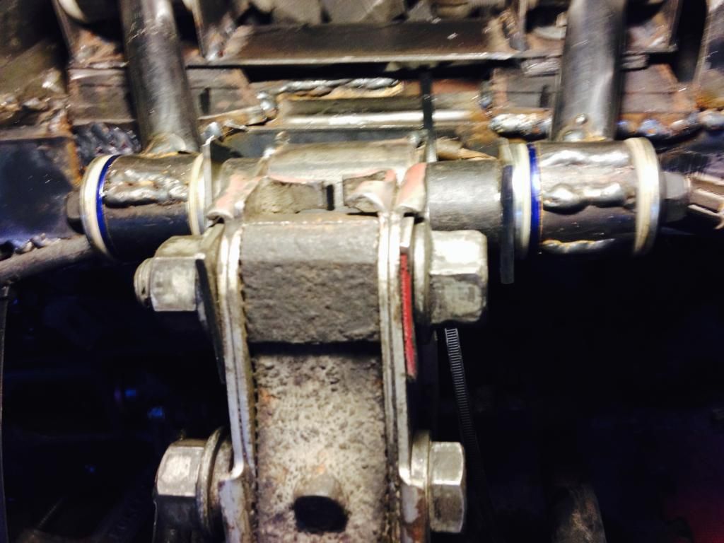
Going to see if I can correct it tomorrow .I do not want to have to unbolt the control arm mounts to make small changes .
|
|
|
|
wftb
|
JAN 24, 02:52 PM
|
|
Looks like it will not be possible to flip the mount to make the cam bolt work to change camber . Right now , rotating the cam bolt just gives a small adjustment to upper arm angle .I put the RCC arm back on .I had a bit of work to get the ball joint stud to fit tight in to the spindle . The gap was full of crud and rust so it would not pinch tight on the stud .Also the bolt was worn , allowing some unwanted up and down slop .I cleaned out the crap with my grinder and a thin cut off wheel and used the good bolt out of my bumpsteer arm and now it fits factory tight .The upper arm mounts were tightened down at a "best guess" position with regards to camber .Toe position right now was determined by the bumpsteer arm setting and should be close to factory setting . So I bolted it all together and took some measurements .At ride height I got lucky as my guesstimate gave me 1 degree negative camber , a good starting position .Going up and 1 1/2" both ways from ride height results in no camber change .A slight positive camber change occurs in the upper areas of compression travel and it goes more negative at full droop .Nothing to worry about there as suspension will almost never be in those positions on the road .The thing I am very happy about is that throughout the normal range of motion I could not measure any toe change .From full droop to upper limit of travel is less than 1/32" of toe in .Again , nothing that will happen during normal driving .The one area that I feel the need to improve on is resistance to flex .It could just be that I do not have the new mounts welded to the strut supports yet and the lower arm is not bolted tight to the cradle yet , but reefing on the backwards mounted disc does give a very small amount of movement .To make sure I can eliminate the unwanted movement , I think I can add some angle brackets from the outer side of the arms to the most inboard part of the strut mount .This should get rid of what little movement there is , and improve the mount to double shear .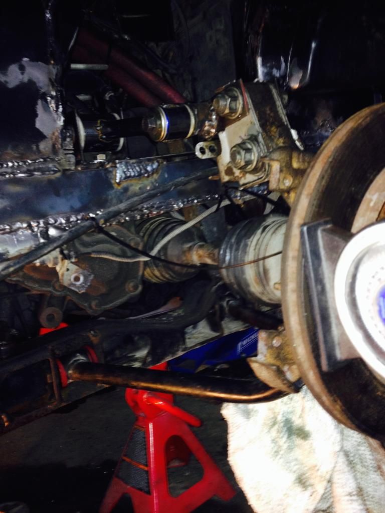 The arms at ride height are level and paralell to each other .There is no binding going up and down , very smooth .Now I need to get the proper tubing I need to make the finished arms and build the extra braces .I think I have a basic design that should work . The arms at ride height are level and paralell to each other .There is no binding going up and down , very smooth .Now I need to get the proper tubing I need to make the finished arms and build the extra braces .I think I have a basic design that should work .[This message has been edited by wftb (edited 01-24-2015).]
|
|
|
|
wftb
|
JAN 24, 03:03 PM
|
|
In this pic , you can see where I can weld in some angled brackets to eliminate flex .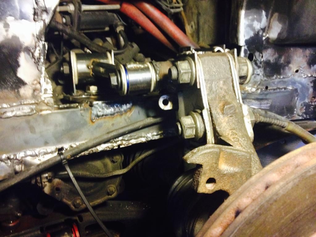
|
|
|
|
wftb
|
JAN 25, 02:09 PM
|
|
|
Now that I got some daylight on the subject , I can clearly see that the movement is caused by not having the lower arm mounting bolts tightened .Going to make the braces any way , but they are not really needed .
|
|
|
|
wftb
|
JAN 25, 04:52 PM
|
|
Looks like i can only make a brace for one side .If I put one on both sides , I won't be able to get the mount bolts in .One brace is adequate from what I can see any way .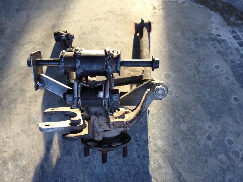
I think there is a little confusion about how this is supposed to work .So to go from the bottom to the top , this is the setup:
RCC lower control arm with stock ball joint
Stock spindle
No toe link arm
Custom built upper arm mount welded to the cut off bottom of the original strut assembly and bolted to the stock spindle with stock mounting bolts
Custom built upper control arms with delrin inner and outer bushings.
QA1 coilovers pivot mounted top and bottom.I have not quite figured out how I am going to mount the coilovers yet , but I have a rough idea that will work I hope .As you can see by the picture , I have more welding and some clean up grinding to do .I just ran out of propane so that is why I am posting instead of working .My garage is not insulated so I use a propane heater to stop from freezing out there .The garage is well ventilated , so the fumes are not a problem .The picture shows the bumpsteer arm attached to the arm mount .I just use it as a "holder" while I weld .[This message has been edited by wftb (edited 01-25-2015).]
|
|
|
|
wftb
|
JAN 25, 09:37 PM
|
|
All welded up .Needs more smoothing with the grinder before I paint this assembly .I found a place in Mississauga where I can get the right tubing to build the arms with , might go down there tomorrow .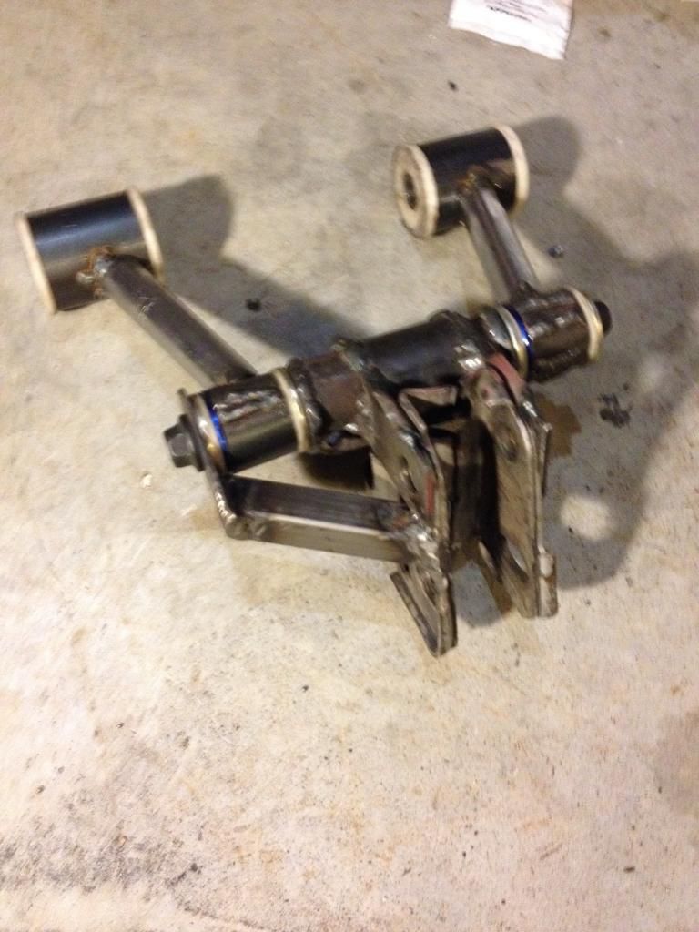
|
|
|
|
Bloozberry
|
JAN 25, 09:55 PM
|
|
|
Where are you planning to attach the shock/strut?
|
|
|
|
wftb
|
JAN 25, 10:40 PM
|
|
|
The pivot mount will be outboard of the pipe that is welded in the middle and between there and the the spindle stub .It will not fit down completely in between but I can get it recessed in about halfway .I have not decided exactly where to mount the top of the coilover yet .I do not know what angle I want to put the coilover at yet .It cannot go straight up like the strut because then shock travel would equal wheel travel would equal broken shocks .Have to get the right ratio there .
|
|
|
|


