
 
     |
| Trinten's SBC/F23 build - The work has begun! (Page 63/76) |

|
Trinten
|
JUN 14, 07:56 PM
|
|
So the good news, Mike and I are still going to be at Carlisle!
The bad news, the car won't be moving under it's own power yet. Mike had some work obligations this past weekend, and is unavailable this upcoming Saturday as well. That leaves us with just the last Sunday before Carlisle. We'll likely focus on the few easy things, some hoses and other quasi-cosmetic things that won't need to be undone when we continue the work.
Even if we hadn't lost those days, it's not likely it would be under it's own power. We still needed to finish wiring up Deutsch connectors in the front (and that is surprisingly time consuming), a few hoses, etc.
|
|
|
|
Trinten
|
JUN 19, 11:49 PM
|
|
Trying to get last minute things buttoned up before Carlisle this week. Putting in correct hardware, instead of placeholder stuff (there's still some placeholder stuff), connecting as many lines as possible, etc.
Mike was busy last week and yesterday, so today was just all that stuff. Which meant hunting through boxes for the specific things we needed. Mike cooked up a clamp on adapter for the Fiero coolant lines, so we didn't have to modify them (more). Brakes were put back on, and (most) of the clips and such for the brake hard lines were re-attached.
We ran power to the starter to spin the engine (no spark plugs were in it, so no compression) just to get oil to circulate. Cautious to not burn out the starter, we would do this for about 15 seconds or so at a time, then let it rest for a while, rinse and repeat. No compression also meant less stress on the starter. We heard the tone change as all the air pushed out of the system though the breather, and oil was just circling around.
The only 'leak' was that the oil filter (of all things!) was not securely screwed in place. 1.5 turns later, and that 'leak' was gone!
We then went about to put the spark plugs in... yeahhhh. About that. The rear set weren't an issue, I was able to get all four started and finger tight with just my hand.
The front set were not able to get started from underneath (my own fault, it's from the exhaust manifolds stock bolt-on heat shield). Also from the top wasn't possible because of the stock coil pack setup. So we removed that coil pack, which was fairly difficult. We also had to pop out the stock LS4 dipstick which was in the way (with the angles/room we had to work with). We knew the stock dipstick/tube was going to be an issue anyway, so it's no big issue that we worked it free for now.
If we stick with the stock coil packs, we'll secure it using just the bolts that were easy to get to. I had the idea of seeing if there's some sort of "quick disconnect" stud-based setup. So I'll have to do some searching on that later.
With the coil pack rack out of the way, we were able to get the spark plugs in from the top without much trouble. I talked to Mike about considering doing a remote coil setup like FieroGuru has done, he said he'd think about it. It would mean making or buying another set of spark plug wires, but really, a small expense in the grand scheme of things if we go that route.
|
|
|
|
Trinten
|
JUL 31, 11:20 AM
|
|
I know it's been a while since I've done a substantive update. What we've been working on hasn't really provided a lot of "photo opportunities", though I realized today I should probably document things for my own memory, if nothing else.
We're waiting for some things to come back from powder coating, and realized we missed a few things that should have gone out with that batch.
Included in that are the headlight buckets for the dual 60mm Hella setup, as well as the surge tank. I've already forgotten what else was in that batch... (see why I thought I should post?)
So when that gets back, there will be pics.
The surge tank had to go through a few revisions, because we needed to preserve room for the Spal fan that will be under the passenger side decklid vent, pushing hot air up (out) of the engine compartment. Mike finished mounting the oil catch can. When I have the other pics, I'll post up pictures of that.
Throttle linkage is done, we did have to use a barrel-style clamp to extend the cable, which Mike dislikes because it makes it 'obvious' that it doesn't belong. He's also not thrilled with the Lokar connector to the throttle body, it's made of plastic. So I might need to find someone who has or can make a metal version of it.
Shift cable is connected and working (if I talked about this before, I apologize). It had to be installed backwards, which also meant Mike had to modify the shifter assembly to change-and-move the bracket that the cable secures into, so the adjustable portion could be used if needed. We also had to flip the transmission lever 180 degrees so it worked as intended (front wheel drive transmission in back of the car, things were shifting "the wrong direction", if that makes sense. Moving the shifter towards park, would shift the transmission away from park).
Right now Mike is busy getting sensors in place and finishing securing/clamping tubes and hoses. He also started his plan for the main positive power cable. He wanted to run it right along the rocker panel area, using angle aluminum to make a bracket and shield that would bolt on by replacing the rocker panel plastic rivets with nuts/bolts, and p-clamps to hold the cable in place. It didn't quite work out, so his next idea is to take the rocker panel off, and "hide" the cable in that cavity, and rework the bracket setup.
Once all of the hoses and tubing are finished up, we'll do leak tests (where possible without a running engine) and then he's going to be focused on wiring for the engine, transmission and controller.
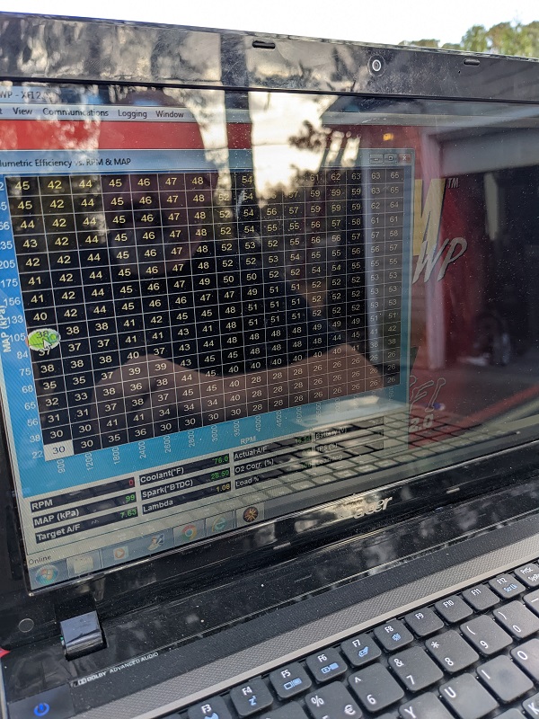
My task this week is to look at the wiring diagrams from FAST for the transmission controller and make sure I have spools of all the right colors/stripes of wire. If I'm missing any, I'll be ordering more spools... lol
[This message has been edited by Trinten (edited 03-26-2023).]
|
|
|
|
Trinten
|
AUG 23, 11:26 PM
|
|
Progress!
There's actually been quite a bit, though not a lot of it is photogenic, mostly Mike putting on wire terminals. I do have some pictures though!
The headlight buckets, surge tank, and last section of intake tube all powder coated.
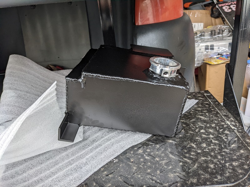
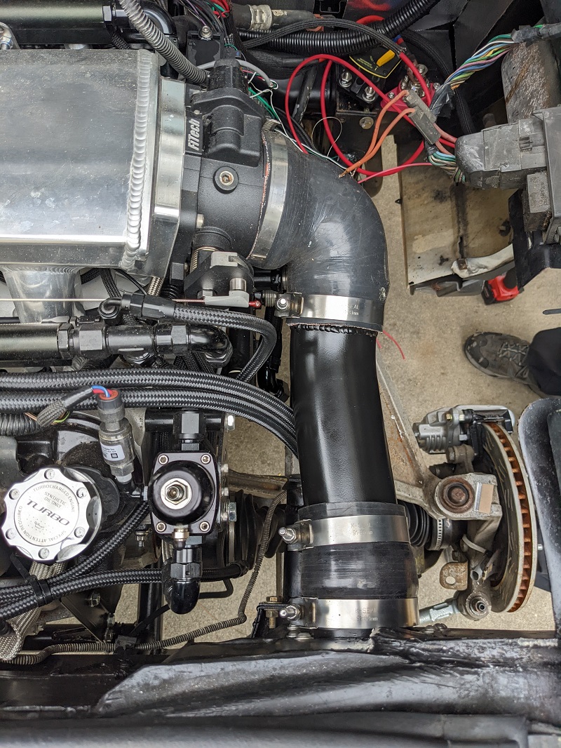
We also mocked up then mounted the surge tank. The picture I took was during the mockup, for those eagle eyes that notice the clamp missing from the intake.
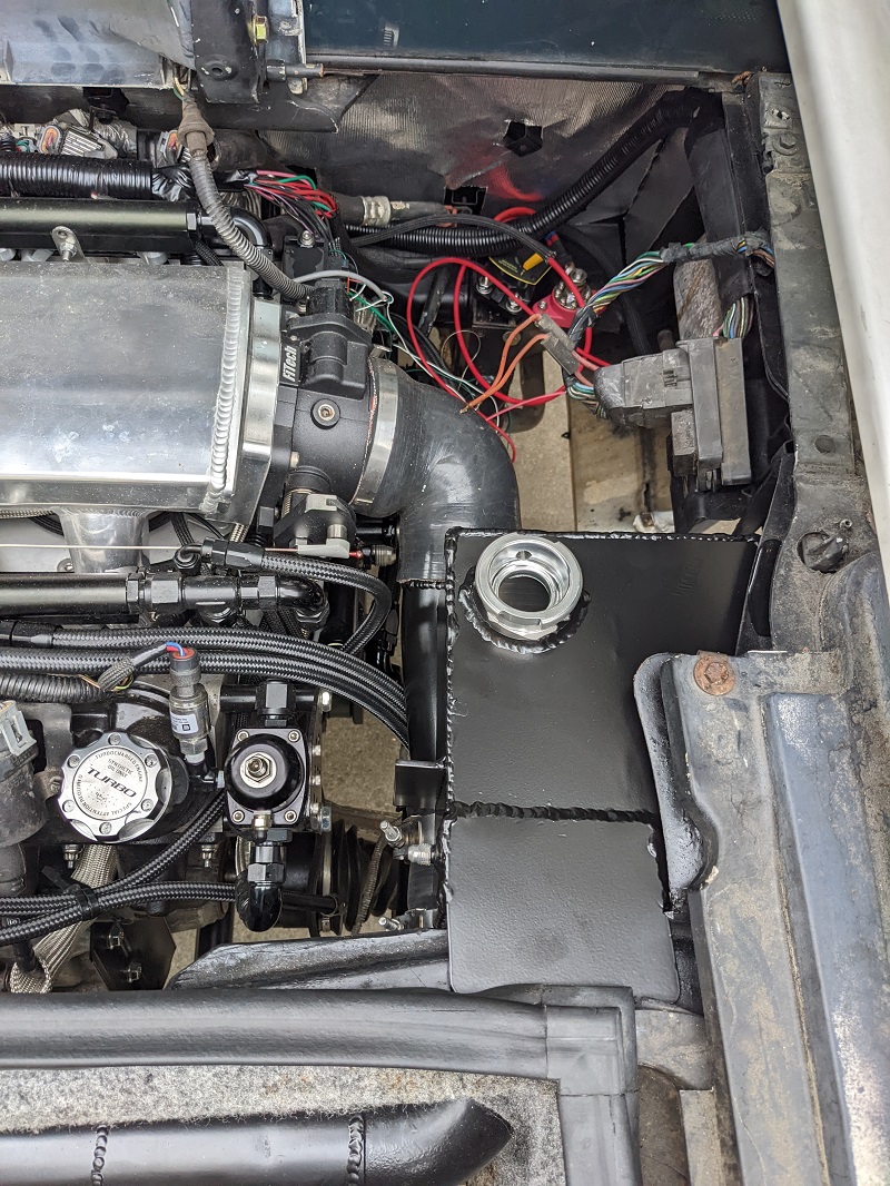
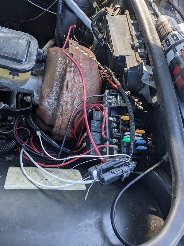
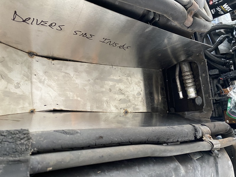
I bought a power distribution block and a UL listed 100A waterproof breaker. They will be mounted in that little spot. The block is already mounted in place. The breaker will go next to it.
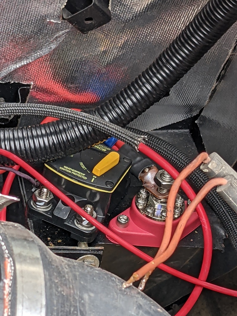
After some checking, we are currently planning on running the main power cable through the cabin.I think Mike is going to use the (currently capped) hole that the clutch went through, then over to behind the center console, and up from there with all the other wiring. I have no idea if having that giant power supply line is going to kick off any EM Noise, so I'm going to ask Mike to to put RF suppression wrap around it. I suspect there will be eye rolling. Maybe not.
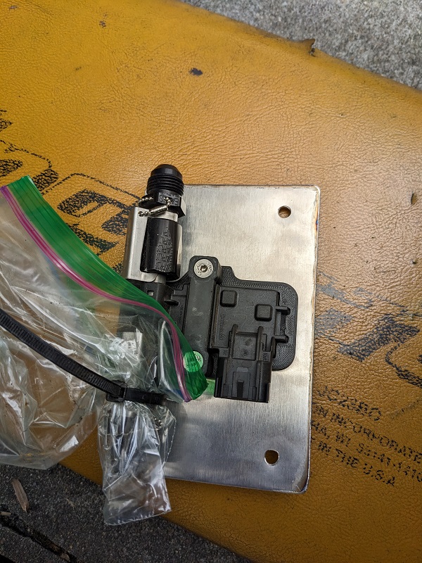
I was under the car to put on the torque converter bolts (ARP of course), and just thought everything looked so awesome, I took a picture. There's only one thing I realized we didn't powder coat - the plate that the flex fuel sensor is mounted to. So I'll have to get that off and just hit it with some VHT paint or something.
Mike also needed some additional stock wiring stuff, which CowsPatoot was kind enough to send over.
He had me get some electrical bulkhead connectors, and more terminals for the heavy gauge positive and negative cable I bought, that's going to be there before this weekend.
So right now, it's lots, and lots, and lots of wiring. This weekend I'll probably mess around and (somewhat pointlessly as they are working okay) rebuild the headlight motors with the kits I bought from Rodney. I got the kits that have the new bushings and the aluminum gears. Just gives me something to do while I'm hanging out. ... damn. I bought those kits a while ago. I need to find where I put them.
We still have to make the stainless fuel tank. Right now it looks like that'll be after all of the wiring is done.
OH! Does anyone know the thread pitch of the decklid vent screws? We lost the j-nuts, and I keep forgetting to take one of the darn things with me to Ace hardware to figure it out. I see the FieroStore sells a different retainer, looks like a round disk type? Those wont' work with the new mounting point that Mike is making for the decklid vent.[This message has been edited by Trinten (edited 03-26-2023).]
|
|
|
|
Trinten
|
SEP 18, 03:35 PM
|
|
Hey everyone,
As I mentioned last time, we're doing wiring! ... okay, Mike is doing wiring. I do other things.
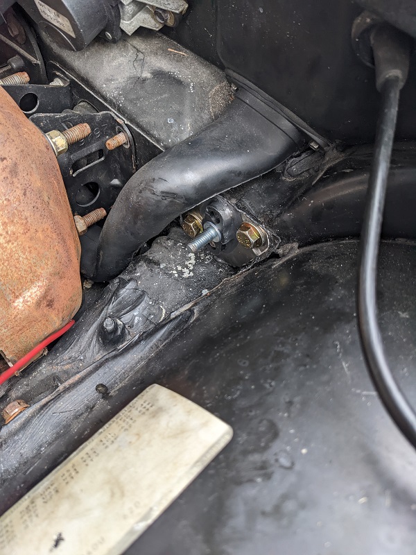
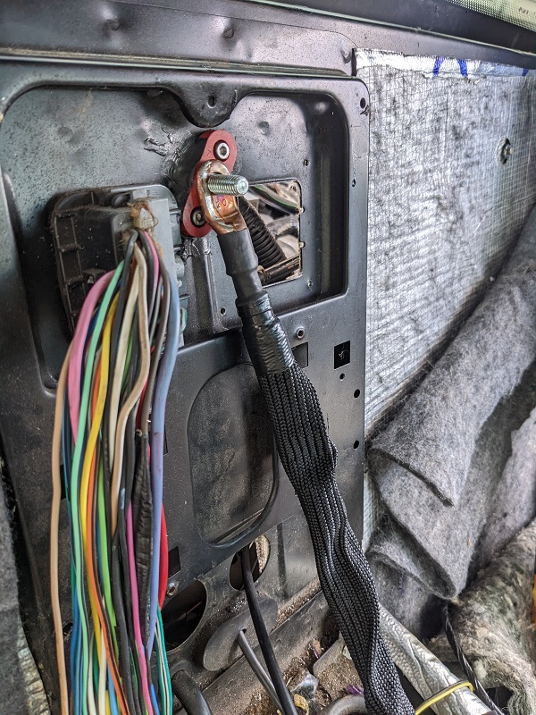
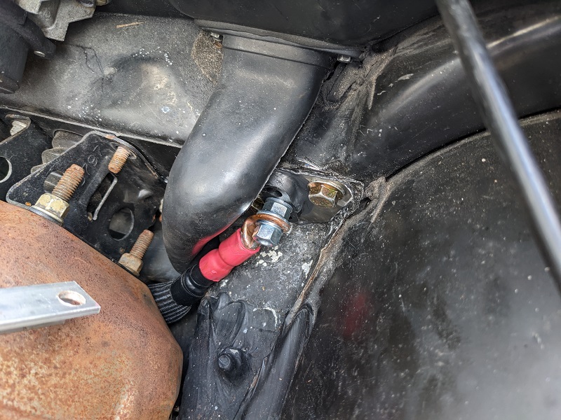
Last weekend Mike installed the power distribution bulkhead pass-through. Instead of running the main power cable under the car as many Fiero owners do, we are running it through the car cabin.
He repurposed the bulkhead opening where the clutch master cylinder was located, and then made a spot for the second pass through in the rear where other wiring for the car moves through.
Frunk:
Rear of cabin:
We put on the high abrasion protection sleeve I had bought, even though it isn't red. I tracked down some red boots with the proper diameter to use, and installed those at all points. I didn't take a picture of the frunk-side after I put the boot on. So here is a picture of the cable bolted in when we were doing test fitting.
And here it is in the engine compartment, the sleeve here is both abrasion resistant and has a very high temp protection.
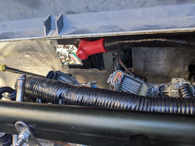
Once everything was done with running the main power, we put the aux. fuse box pack into place.
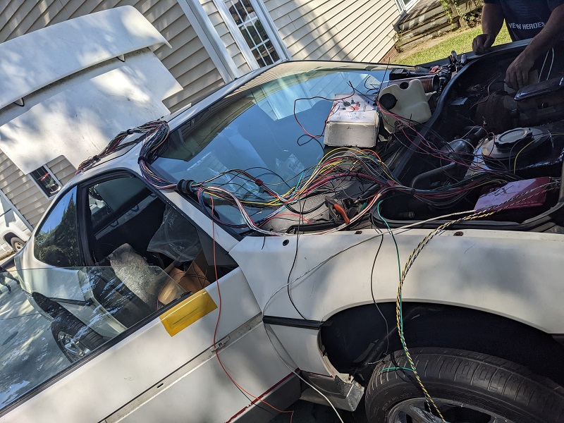
Mike then got out the partial ECU wire harness components he had made over the last few years, and it was long enough to where he could lay it over the car and connect all points. He said this will make it really easy to test pin-outs and do any troubleshooting.
I joked that we should just p-clamp it to the body like that when it was done and call it a day.
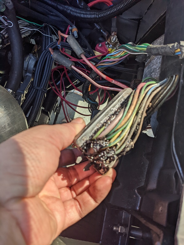
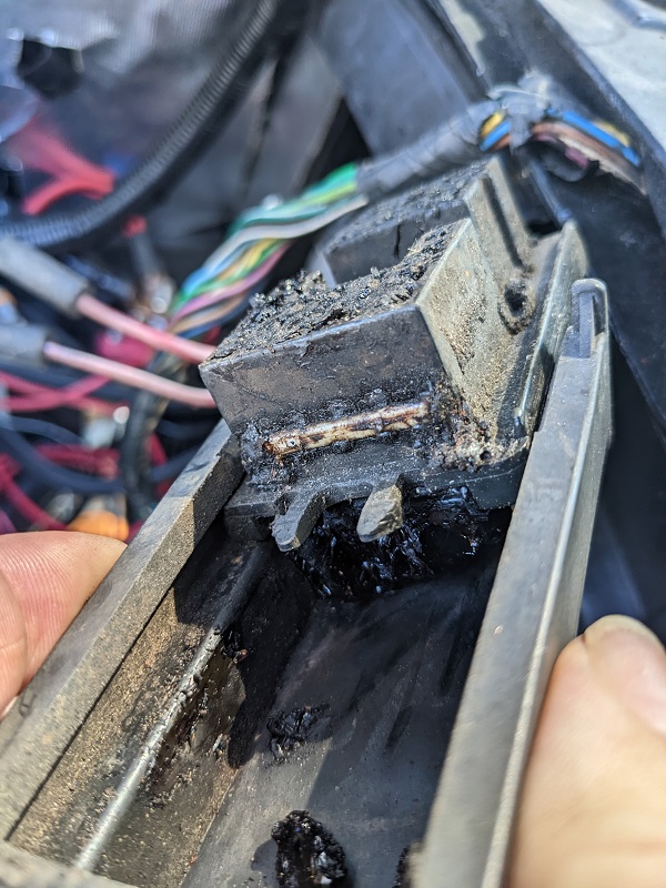
The last thing I worked on was the C500 starter pin-out issue. I think I mentioned last time we found out (the hard way) that the C500 engine connectors had different pinouts, and the starter wire is in a different spot on the auto-transmission Fiero vs. the manual.
I did a post looking for the connector I needed, and Raydar suggested I disassemble the body-side of the C500 and move the pin.
So I opened that thing up... and put it back together. It's understandably full of the non-conductive weather protection goop, and I believe the white strips are the edges of the wire locks he told me about, which were also caked up in dirt/grime/goop.
At this time, I'm going to keep hunting for the proper engine side of the connector. Repinning the C500 will be a last resort.
[This message has been edited by Trinten (edited 03-26-2023).]
|
|
|
|
Trinten
|
NOV 06, 12:16 AM
|
|
Sorry it's been a while guys. Between me being out of town, Mike having to work some weekends, and the fact that wiring is a slow and tedious process, progress has been slow!
To go back a little to a post I did in July when I talked about the shifter cable (and having to install it backwards), I did find I took pictures of it!
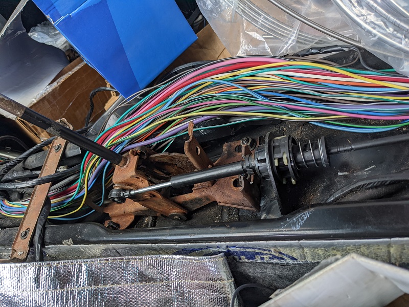
You can see in the first picture, Mike modified the back section of the Fiero shifter assembly with a part from the Caddilac shifter bracket that was originally by the transmission. This was to secure the cable properly and allow it to be adjusted. When installed "the right way", the non-flexible arm was too long.
The second picture is the new mount that Mike created for the transmission side. This is a two plate system that 'clamps' around the cables bracket engagement. we tested and adjusted the shifter through all the gears, and it's all working.
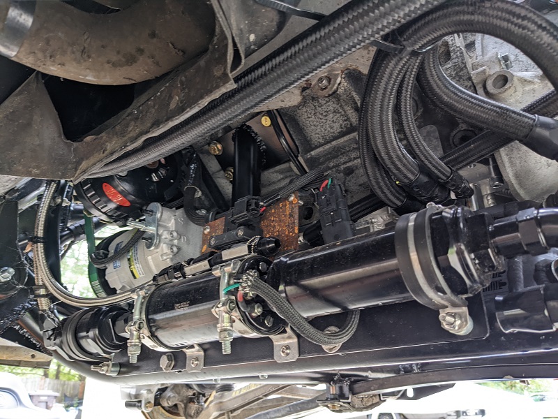
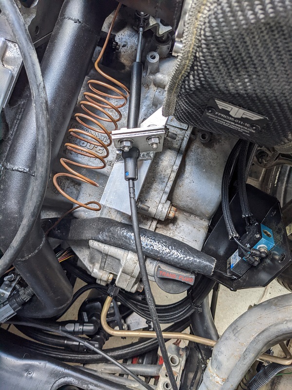
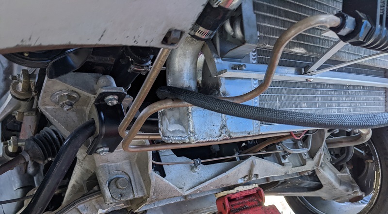
I was under the car at one point, and took a moment to admire the time and effort Mike put into bending all that tubing for the transmission cooler. There were a LOT of bends. Looks freakin' factory!
So onto more recent things!
The first/current engine harness was used by modifying the original LS4 harness. This made troubleshooting things a little more difficult (ohming stuff out or what not), because the engine harness colors don't match the XFI colors, and while the Deutsch connectors are designed to cram as many connection points in there as possible with their spiral setup, it does make tracking pins/wires when flipping things around pretty damn tough.
Thankfully the issues we had were very few, and today, with 'key on', the XFI came to life (along with the EHPS pump) and saw input from all the (connected) sensors!
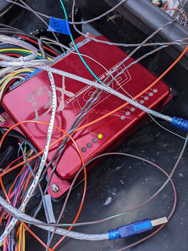
We were both very excited by that. There's still a few more sensors we need to get terminal kits for and finish pinning/wiring them, that will be next weekend, and then Mike hopes to "bump" the engine. Not run it for very long, just long enough to make sure the XFI is reading everything and it all looks correct.
After that will be finishing running the intercooler tubing, top off fluids, I think we still need to do the bracket for the oil dipstick to secure that in place, then rig up a fuel cell while we do idle tuning and check for leaks.
After all that, is fabrication of the fuel tank, fab up the hoses to go from it to the fuel pump, and wiring to make the gauge cluster work.
Also, I'm still trying to chase down a 86+ Fiero Engine harness from a car with a manual transmission. One vendor on here dug out his harnesses and sent me pictures, I identified the one I needed... but after asking him for a price, I haven't heard anything back in a few weeks, even after chasing.
Another vendor has been telling me they'll check, and then I wouldn't hear back until I chased them. Finally I indirectly asked them if they just didn't want my business, that got their attention and they asked me to call them tomorrow.
If all else fails, Mike will "cook down" the C500 connector we have and repin it, and we'll get more of that tar-goop to waterproof it.[This message has been edited by Trinten (edited 03-26-2023).]
|
|

|
Trinten
|
NOV 21, 10:52 PM
|
|
It lives!
We finished getting wiring from the FAST modules to the engine (and after some head scratching with decisions made by GM around the cam sensor, and clarifying information from FieroGuru), we sprayed some fuel into the intake and did a very short run to make sure everything was working correctly. I did record it, but it was only a few seconds long, so I figure I'll wait until we have a constant fuel supply running to it and post up a longer then.
Mike won't around this weekend on account of Thanksgiving, so the next time I'll be out there will be December 3rd. The plan then is to run a hose into a gas container and start doing some basic tuning, and if time allows, have another can with some E85 so we can confirm the flex fuel sensor is working as intended.
Now I did (finally) find an 87-88 engine Fiero Harness from a manual car on eBay, from a guy that I've bought from before out in Nevada (no, not Archie, this guy is also named Mike, strangely enough). This was after striking out with Jon at Fiero Service (very busy guy, not great with follow-up communication, I had to do a lot of chasing).
I thought I had a lead with Larry as well - say what you will, Larry did come through for me on the D-plates. He even sent me pictures of harnesses and I spotted one that looked correct, emailed him back a few times asking him to for pricing, didn't hear back.
Either way, I got one! So we hooked it up, and the ignition key didn't fire the starter. This was a head-scratcher for us, because we had toned this out before when discovering we had the wrong C500 to start with. So instead of putting more time into that, we just used a jumper wire to manually trigger the starter from the engine compartment.
Only other hiccup is with the FAST software. Mike has it installed on a few laptops. The software auto-updates (I need to fix that in the hostnames file), so now, one one of his laptops, the newest software won't talk to my setup anymore. It probably requires sending my FAST units in to be flashed if it's not something I can do myself. I'm not planning on messing with that. I have the same version of the software installed on one of my laptops that Mike has on the laptop that is still working for him, so I'll just need to make sure to 127.0.0.0 the FAST software on it.
Also it's strange they don't have a direct USB cable yet, it still uses a serial cable, and then we use a serial-to-usb adapter. FAST sells a serial to usb adapter... for like 50 bucks. The 9 dollar one I have works just fine. lol
Anyhow, the point is, the engine lives! Woot!
[This message has been edited by Trinten (edited 03-26-2023).]
|
|
|
|
Trinten
|
DEC 04, 11:21 PM
|
|
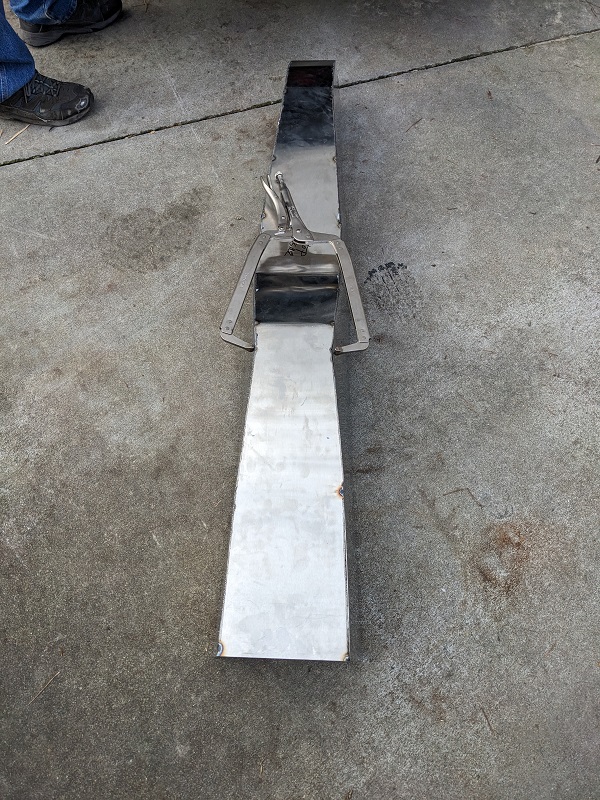
Gas tank construction begins
Slow but important progress today.
Last week Mike had gotten back his cardboard mock-ups for the fuel tank. He gave me the measurements and I ordered the 304 stainless.
Today was marking up the material and doing a lot of careful plasma cutting! Mike wanted to maximize the use of the space, and as FieroGuru has pointed out in other posts about making tanks, that is a difference between total volume and usable capacity. So we're trying to make sure any increases in volume will yield a reasonable increase of usable capacity. Because of the approach, there were a fair number of compound curves, but thanks to the effort on the mockup and the clean cuts of the plasma cutter, things are coming together pretty well so far.
Unfortunately, my phone decided to freak out and has stumbled into constant-reboot (rarely even reaching the lock screen, and will even reboot when I get to the factory recovery screen... so I think it's pooched). I don't do the whole 'cloud backup' thing, either. Unfortunately my paranoia on cyber security has also made it tough for me to setup things on my replacement phone. lol. Oh well. I'll get it worked out eventually, but any pics I hadn't already copied from phone to computer are gone - barring some miracle combination of buttons to get my phone to be stable long enough to copy things off. I'm not holding my breath.
So the pics we have are ones I took with Mike's phone that he emailed to me, which were after enough of the tank was tacked up to start doing test fitting.
We're going to move where the rubber hose comes from the fill tube into the tank, so I need to find the measurements of the ID and OD of that hose and get one that is longer at both legs (for both the fill hose and the breather).
Deatschwerks makes an adjustable fuel sender that we will likely use.
Mike started mocking up the trapdoor and the "sloshwall" in the tank. The trapdoor will be about a 1/3 from the back third, and another thing I'm going to call a "slosh wall" because I don't recall what he called it (a panel with a small cut out at top and bottom) about 1/3 from the front.
Here are the pics of the tacked-up, partially assembled tank shoved into the car for fitment checks.
[This message has been edited by Trinten (edited 03-26-2023).]
|
|
|
|
Trinten
|
DEC 11, 04:08 PM
|
|
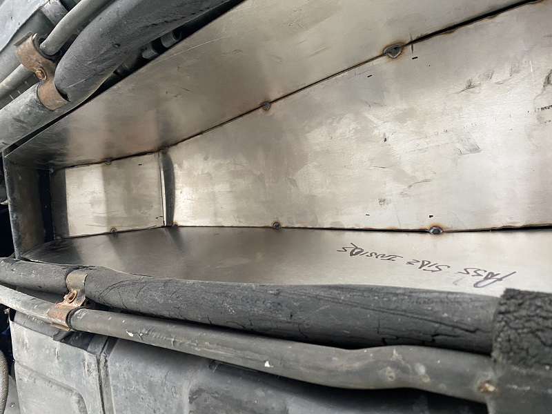
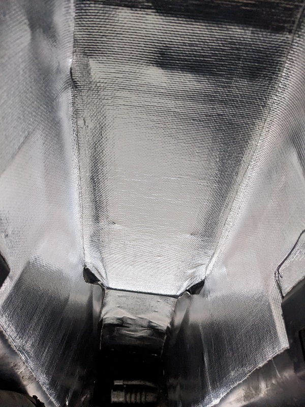
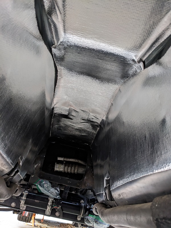
This weekend was more working on the fuel tank, and a few other odds and ends once we reached out limits with the tank for today. As mentioned before, the tunnel has some hourglass / mirrored sawtooth curves to it, so the top of the tank follows that.
Using a giant C-clamp we will bring in the sides to weld it without putting creases in the tank that don't need to be there. Before we do that we're going to get the baffles and trapdoor put in to add rigidity to the sidewalls. The bottom of the tank is marginally trapezoid shaped, so there will be an opening where the baffles can be tacked to the flat/wide bottom, before the angled corners are welded on.
It's slow going, a lot of measurements, marking and careful cutting with the plasma cutter using tall angle iron clamped on for guides.
Mike's also given me the information and plans for the fuel level sender he wants, and how he's going to run the fill and pickup piping. When it's all done and we do our leak test, we'll empty it by pumping it out through the pick-up into 5 gallon buckets, so we can get a measurement of the useable capacity.
I took the time to clean out the tank tunnel, and put in temp/sound insulating material. You can see how some of those curves, especially at the top came into place with fitting in the insulation. After I took these pics I used some small pieces to fill in the exposed spots.

Previously when under the car I noticed the plate we made to mount the flex fuel sensor had started to rust. I thought it was a part we forgot to send off for powdercoating, Mike said he thought we had made it out of stainless (apparently not). So I took that off and he used some of the 304 I got for the fuel tank to make a new plate.
Mike also did a test fit of the wheel well covers, and was amazed to see they fit in there and around the Corvette suspension without any major issues.
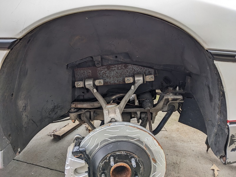
The mounting bracket for the upper control arm is not welded in yet. Mike wants to get the car to an alignment shop and make sure everything aligns properly with plenty of adjustment room left before he welds them in.
[This message has been edited by Trinten (edited 03-26-2023).]
|
|
|
|
La fiera
|
DEC 12, 09:52 PM
|
|
|
|
|
