|
| Chrysler 3.5 HO V6 swap (Page 6/33) |

|
diabloroadster
|
NOV 16, 09:35 PM
|
|
| quote | Originally posted by seajai:
I was looking into using the megasquirt and megashift to control everything. The 41TE is pretty much the same electrically as the 42LE so it would be an easy deal. The problem with the megasquirt is controlling coil-on-plug ignition. There was supposed to be a sequencer in development for that but it didn't look like it was going to come to fruition. Also, I have read somewhere that the megasquirt fuel injector MOSFET's can overheat and burn out.
In 2002 Chrysler combined the TCM and the PCM so I only have 1 computer to deal with on mine. The great thing about having a complete running donor car was I could do some experimenting and determine that, even with all of the other modules disconnected from the CAN BUS, the engine ran fine and the cluster still worked and I didn't get the dreaded "NO BUS" error message. So in the end, I have decided to use the factory computer, it should work fine for me, and there are a few places that can remove the immobilizer programming as well as remove traction control, etc for less than what a stand-alone system would cost me.
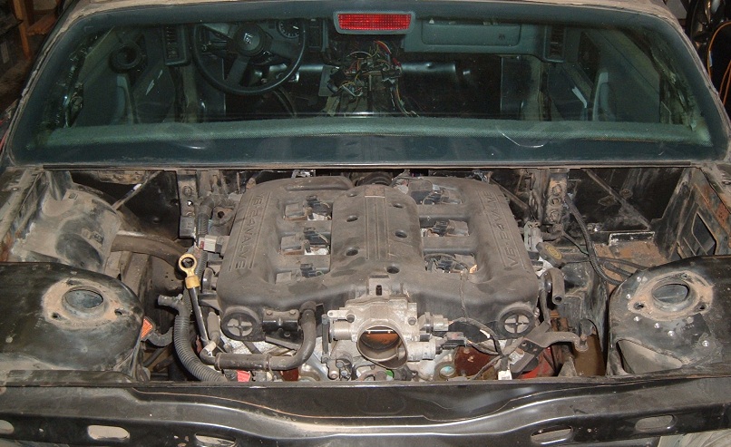
My main drive on the project was just to do something that has never been done before. Although, with 253HP and 250 ft lbs of torque, the Chrysler engine should make the Fiero scoot pretty well.
|
|
If you cant get the factory PCM working let me know, I can help you get a megasquirt /msd6010 together that should work with the coil on plug setup. Im currently working with a Microsquirt2 only running both the fuel and spark on a LS1 off the stock crank trigger & waste spark. But my experience (very little) is only with LS engines, although I know some folks that are genius's with this stuff.
Good luck with your project!
|
|
|
|
engine man
|
NOV 17, 05:01 AM
|
|
seajai great project way to think outside the box I will be keeping my eye on your progress
|
|
|
|
seajai
|
NOV 21, 07:22 PM
|
|
|

|
Fierofreak00
|
NOV 21, 09:52 PM
|
|
 I like it! -Jason I like it! -Jason
|
|
|
|
Hardpact
|
NOV 22, 07:43 AM
|
|
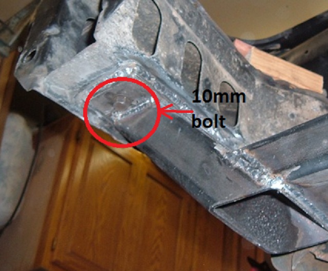
Very interesting !! Just one question ... Looks like your welding the cross member in are you welding that to the bolt in cradle ?? Cause the back looks like your welding it to the car if you are how are you going to remove the motor ? This looks like a great swap hope this works good !!
~Tom------------------

BLUE BY YOU!
NYFOC
|
|
|
|
seajai
|
NOV 22, 09:25 AM
|
|
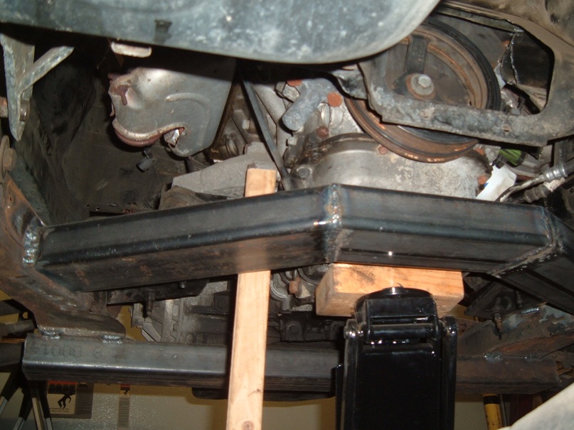
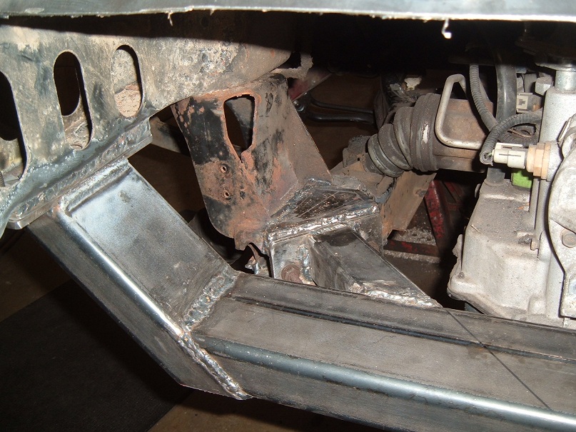
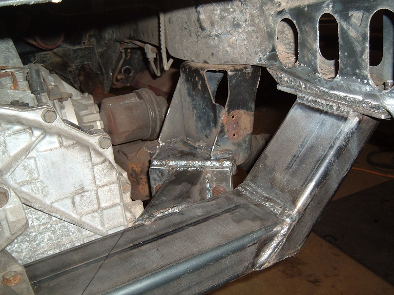
| quote | Originally posted by Hardpact:
Very interesting !! Just one question ... Looks like your welding the cross member in are you welding that to the bolt in cradle ?? Cause the back looks like your welding it to the car if you are how are you going to remove the motor ? This looks like a great swap hope this works good !!
~Tom
|
|
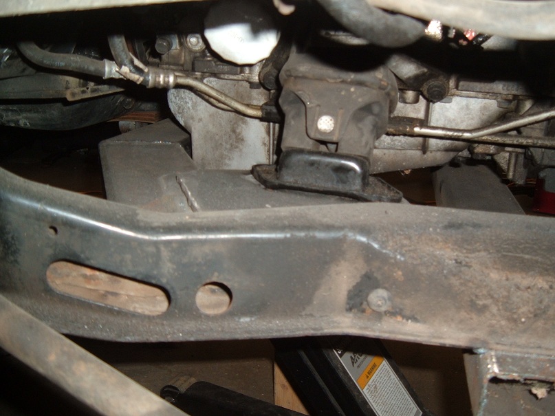
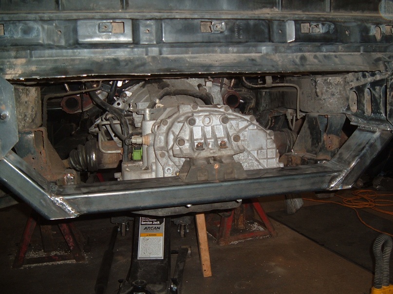
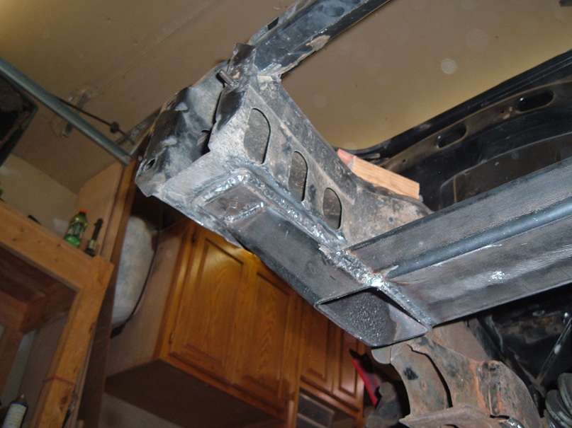
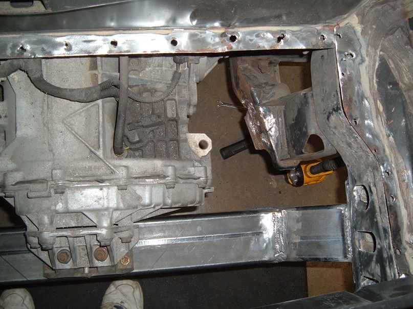
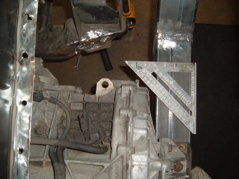
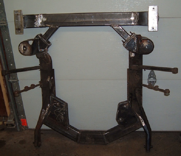
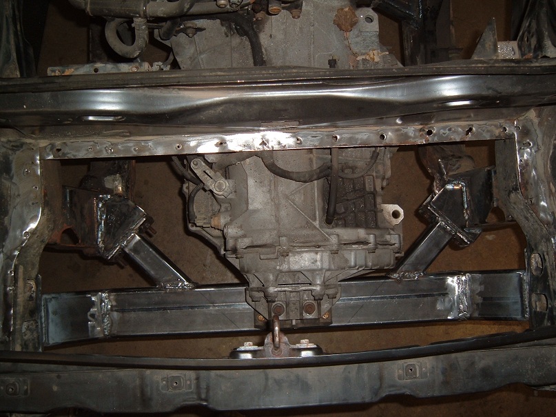
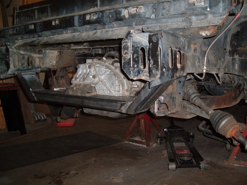
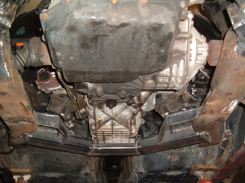
The transmission cross member is bolted to the body so it is removable. I made two 1/4" thick plates, drilled and bolted them together and welded the nut to the top plate, I then unbolted the plates. After the lower plate was welded to the car, I reinstalled the top plate to the cross member to align it. The cross member was positioned in the car and the top plates were tacked to the rails. I pulled out the bolts and removed the cross member, and the top plates were finish welded to the body. There are four 10 x 1.5MM bolts holding it in place.
I gotta give a huge thanks to my brother for helping me on this phase of the project. His equipment and welding experience was the only way it was going to happen. I'm a woodworker, so I have design and fab skills, just not with metal. And my welding skills, well, let's just say I need a little more practice.[This message has been edited by seajai (edited 09-28-2023).]
|
|
|
|
VF1Skullangel
|
NOV 22, 10:21 AM
|
|
|
I wonder if the 3.3 out of the dodge intrepid will work. I had one and those were bullet proof engines. To bad the Transmissions where weak on those cars. No matter how much you take care of them they where junk.
|
|
|
|
seajai
|
NOV 25, 07:36 PM
|
|
|
|
|
engine man
|
NOV 25, 07:59 PM
|
|
|
nice job and i under stand about laying there and staring at it you have to get a mental picture of how it will all go together
|
|
|
|
Hardpact
|
NOV 25, 09:42 PM
|
|
|
Sorry was hard to see the bolt !! Great job in the design !! ------------------
BLUE BY YOU!
NYFOC
|
|
|