
 
     |
| Blooze Own: An F355 Six Speed N* Build Thread (Page 58/126) |

|
Bloozberry
|
NOV 30, 04:14 PM
|
|
Before being able to determine the location of the new pushrod shock absorber system, I needed to get a better idea how large and what shape the bell crank needed to be. The physical size and shape of the bell crank and the shock absorber would help to determine where they can be mounted or if any compromises would have to be made to package them in the space available.
I did about as much research on the internet on push rod suspension bell cranks as possible only to find very little has been written about the geometry considerations, and no one seems to offer any "off the shelf" designs... likely because of the huge number of variables. So in ploughing ahead with my own design, I discovered through trial and error that pushrod systems have a few design criteria that have to be taken into consideration to work properly. Some are obvious, others not so:
a. BELL CRANK SHAPE. The shape of the bell crank determines the way movement in one plane is transferred into another plane. I knew the bell crank would have to be a 90 degree elbow since I wanted to translate the vertical movement of the knuckle (and pushrod) into a longitudinal (fore-and-aft) compression of the shock absorber;
b. CRANK MOTION RATIO. For those aware of the more common definition of suspension motion ratio (where the location of the spring mount on the upper or lower control arm affects the leverage that a wheel has on the spring) the rear suspension on a Fiero has a nearly 1:1 ratio since the spring is attached directly to the knuckle. It's not exactly 1:1 because of the inward tilt of the struts. On this pushrod system, the pushrod is also going to be attached directly to the knuckle, however, depending how long each bell crank arm is made in relation to the other, the travel of the shock absorber can be made to be the same as the input pushrod travel, or a different amount. A bell crank with arms of equal length results in a 1:1 ratio. That is, 25 mm of wheel jounce gets transferred into 25 mm of shock absorber and spring compression. On the other hand, if the arm attached to the shock absorber were twice as long as the one attached to the knuckle (as in a 1:2 ratio bell crank), then 25 mm of wheel travel would result in 50 mm of spring and shock compression (under proper design conditions).
The internet is full of opinions regarding the "best" crank motion ratio, but some make more sense than others. The rationale I favoured was to make as high a motion ratio as possible within the physical constraints of the engine bay. High ratios allow the shock absorber to pump more fluid in the shock than low ratio motions for every increment of wheel travel movement. That in turn allows finer tuning of the shock absorber valve rates on adjustable shocks. It didn't take long for me to realize though that even a 1:1 ratio would give plenty of shock travel... perhaps even too much. Given 76 mm (3") of jounce and the same in rebound meant 6" of travel even with a 1:1 ratio... that's a lot when you start looking up various shock absorber specs... good thing the frame was stretched an additional 3" back there! So I started out with a 1:1 raito to see where it would take me, knowing that if space allowed, I could always increase or decrease the motion ratio later in the design.
c. PUSHROD TRAVEL TO CRANK ARM LENGTH RATIO. Choosing the right length of the bell crank arms was the next hurdle. I needed to determine the length of the bell crank arms such that the full 76 mm (3") of jounce and rebound travel would not result in any binding or large angular change in the pushrods. It's not as simple as making the crank arms 3" long. To explain why, here's an example of a 1:1 travel to crank arm ratio:

As the wheel would compress upwards, the top end of the input pushrod would progressively be pulled away from the vertical by the rotational movement of the bell crank. By the time the full 76 mm (3") of travel were used up, the pushrod would be at about 22 degrees from vertical, splitting a portion of it's travel between upward, and fore-and-aft motions.

The same thing happens at the shock absorber as well, except that during the last portion of jounce travel a portion of the motion would be used up to swing the shock down rather than compress it. This would effectively lower the spring rate at a point when a higher rate would be desirable to prevent bottoming out.
To reduce the angular change in the pushrod (and shock), the bell crank arms must be chosen such that under the full range of jounce and rebound travel, the input pushrod stays as near to vertical, and the shock absorber stays as near to horizontal as possible. The way to accomplish this is to make the bell crank arms as long as possible in relation to the pushrod travel.
Of course space limitations always muddy up the best design considerations, so given the space under the decklid for a bell crank, I chose the crank arm lengths to be 107 mm long, giving a 1:1.4 push rod travel to crank arm length ratio.
Here is conceptual configuration of the bell crank...

And how I envision it will fit in the engine bay along with the pushrod and coil over shock.


Next, I'll show how the pushrod, bell crank, and shock move in jounce and rebound, followed by a discussion on the strength of materials needed to fabricate the bell crank and the choice of pushrods, hemispherical joints, and coil over shocks to support the estimated loads. Then, of course, how I intend to attach the bell crank and the shock mount to the Fiero frame... so lots more to come.
|
|
|
|
Zac88GT
|
DEC 01, 12:19 PM
|
|
|
One more thing with crank shape you may want to consider is the change in motion ratio throughout the suspension movement. You don't have to have the pushrod joint, pivot bearing, and damper joint at a 90* angle. If you were to move the damper mounting location on the crank rearwards but maintain the same vertical height you can get the motion ratio to fall (towards 1:1) with bump which will result in a progressively increasing wheel rate. Essentially you can simulate progressive rate springs with fixed rate ones. Just make sure you don't design it with a falling wheel rate or you'll end up with a lot more body roll and less responsive suspension. Just something to think about.
|
|
|
|
bubbajoexxx
|
DEC 01, 04:10 PM
|
|
| quote | Originally posted by Bloozberry:
Before being able to determine the location of the new pushrod shock absorber system, I needed to get a better idea how large and what shape the bell crank needed to be. The physical size and shape of the bell crank and the shock absorber would help to determine where they can be mounted or if any compromises would have to be made to package them in the space available.
I did about as much research on the internet on push rod suspension bell cranks as possible only to find very little has been written about the geometry considerations, and no one seems to offer any "off the shelf" designs... likely because of the huge number of variables. So in ploughing ahead with my own design, I discovered through trial and error that pushrod systems have a few design criteria that have to be taken into consideration to work properly. Some are obvious, others not so:
a. BELL CRANK SHAPE. The shape of the bell crank determines the way movement in one plane is transferred into another plane. I knew the bell crank would have to be a 90 degree elbow since I wanted to translate the vertical movement of the knuckle (and pushrod) into a longitudinal (fore-and-aft) compression of the shock absorber;
b. CRANK MOTION RATIO. For those aware of the more common definition of suspension motion ratio (where the location of the spring mount on the upper or lower control arm affects the leverage that a wheel has on the spring) the rear suspension on a Fiero has a nearly 1:1 ratio since the spring is attached directly to the knuckle. It's not exactly 1:1 because of the inward tilt of the struts. On this pushrod system, the pushrod is also going to be attached directly to the knuckle, however, depending how long each bell crank arm is made in relation to the other, the travel of the shock absorber can be made to be the same as the input pushrod travel, or a different amount. A bell crank with arms of equal length results in a 1:1 ratio. That is, 25 mm of wheel jounce gets transferred into 25 mm of shock absorber and spring compression. On the other hand, if the arm attached to the shock absorber were twice as long as the one attached to the knuckle (as in a 1:2 ratio bell crank), then 25 mm of wheel travel would result in 50 mm of spring and shock compression (under proper design conditions).
The internet is full of opinions regarding the "best" crank motion ratio, but some make more sense than others. The rationale I favoured was to make as high a motion ratio as possible within the physical constraints of the engine bay. High ratios allow the shock absorber to pump more fluid in the shock than low ratio motions for every increment of wheel travel movement. That in turn allows finer tuning of the shock absorber valve rates on adjustable shocks. It didn't take long for me to realize though that even a 1:1 ratio would give plenty of shock travel... perhaps even too much. Given 76 mm (3") of jounce and the same in rebound meant 6" of travel even with a 1:1 ratio... that's a lot when you start looking up various shock absorber specs... good thing the frame was stretched an additional 3" back there! So I started out with a 1:1 raito to see where it would take me, knowing that if space allowed, I could always increase or decrease the motion ratio later in the design.
c. PUSHROD TRAVEL TO CRANK ARM LENGTH RATIO. Choosing the right length of the bell crank arms was the next hurdle. I needed to determine the length of the bell crank arms such that the full 76 mm (3") of jounce and rebound travel would not result in any binding or large angular change in the pushrods. It's not as simple as making the crank arms 3" long. To explain why, here's an example of a 1:1 travel to crank arm ratio:
As the wheel would compress upwards, the top end of the input pushrod would progressively be pulled away from the vertical by the rotational movement of the bell crank. By the time the full 76 mm (3") of travel were used up, the pushrod would be at about 22 degrees from vertical, splitting a portion of it's travel between upward, and fore-and-aft motions.
The same thing happens at the shock absorber as well, except that during the last portion of jounce travel a portion of the motion would be used up to swing the shock down rather than compress it. This would effectively lower the spring rate at a point when a higher rate would be desirable to prevent bottoming out.
To reduce the angular change in the pushrod (and shock), the bell crank arms must be chosen such that under the full range of jounce and rebound travel, the input pushrod stays as near to vertical, and the shock absorber stays as near to horizontal as possible. The way to accomplish this is to make the bell crank arms as long as possible in relation to the pushrod travel.
Of course space limitations always muddy up the best design considerations, so given the space under the decklid for a bell crank, I chose the crank arm lengths to be 107 mm long, giving a 1:1.4 push rod travel to crank arm length ratio.
Here is conceptual configuration of the bell crank...
And how I envision it will fit in the engine bay along with the pushrod and coil over shock.
Next, I'll show how the pushrod, bell crank, and shock move in jounce and rebound, followed by a discussion on the strength of materials needed to fabricate the bell crank and the choice of pushrods, hemispherical joints, and coil over shocks to support the estimated loads. Then, of course, how I intend to attach the bell crank and the shock mount to the Fiero frame... so lots more to come. |
|
do yourself a faver and use the rear suspension from a c6 corvette as i did will give you a wider track and the geometry you want here is the link some good pics of how its made are here midway down the page http://www.fiero.nl/forum/F.../HTML/000007-33.html
|
|
|
|
Bloozberry
|
DEC 01, 05:56 PM
|
|
Thanks for commenting Zac... you're absolutely right about the changing motion ratio thoughout the suspension movement. I may be well advised to relocate the shock pivot point on the bell crank further back as you suggested. When it comes time, do you believe your Lotus software will be able to analyze a system with a trailing link, two lower lateral links, and an upper control arm (well, two upper links really)?
For Bubbajoe: Thanks for the input and the link. I read through your entire build several years ago. While I admire your innovation and fabrication skills, there are certain aspects of the Corvette front end that leave me wondering how suitable it would be in the rear of a Fiero. Without any analysis it would be difficult to say whether the rear roll center would end up at an appropriate height, nor would it be easy to know how it moved throughout the range of suspension travel. Other issues I'd be concerned about would be that the Corvette front was most likely designed to toe out under compression to induce understeer, while in the Fiero rear the opposite is needed. Then there's issues with the steering tie rod and bump steer, the large amount of anti-squat introduced by those lower control arms, and the transfer of accelerative forces to the frame through control arms that were designed primarily with decelerative forces in mind. By no means do I intend to rain on your parade, but I'm not sure making a Corvette front end work well at the rear of a Fiero would be any easier than what I'm doing now. In fact it might even be more difficult.[This message has been edited by Bloozberry (edited 12-02-2012).]
|
|
|
|
Zac88GT
|
DEC 02, 03:33 AM
|
|
|
There isn't a default template with your configuration but I can probably create a template from scratch or try to modify one that's close already. I'll look into it.
|
|
|
|
Bloozberry
|
DEC 02, 07:45 AM
|
|
Awesome! You're the best Zac! 
|
|
|
|
FieroWannaBe
|
DEC 02, 02:23 PM
|
|
| quote | Originally posted by Bloozberry:
Thanks for commenting Zac... you're absolutely right about the changing motion ratio thoughout the suspension movement. I may be well advised to relocate the shock pivot point on the bell crank further back as you suggested. When it comes time, do you believe your Lotus software will be able to analyze a system with a trailing link, two lower lateral links, and an upper control arm (well, two upper links really)?
For Bubbajoe: Thanks for the input and the link. I read through your entire build several years ago. While I admire your innovation and fabrication skills, there are certain aspects of the Corvette front endl that leave me wondering how suitable it would be in the rear of a Fiero. Without any analysis it would be difficult to say whether the rear roll center would end up at an appropriate height, nor would it be easy to know how it moved throughout the range of suspension travel. Other issues I'd be concerned about would be that the Corvette front was most likely designed to toe out under compression to induce understeer, while in the Fiero rear the opposite is needed. Then there's issues with the steering tie rod and bump steer, the large amount of anti-squat introduced by those lower control arms, and the transfer of accelerative forces to the frame through control arms that were designed primarily with decelerative forces in mind. By no means do I intend to rain on your parade, but I'm not sure making a Corvette front end work well at the rear of a Fiero would be any easier than what I'm doing now. In fact it might even be more difficult.
|
|
You're concerns are legitimate, but GM uses the same components on the front and rear of the Corvette. The mounting positions are changed, but they use the same control arms and uprights. So the rear of an c5/c6 vette has the proper anti squat, camber curve and roll steer. It's a pretty well thought out design. The pieces are forged aluminum. And they are readily available, many aftermarket manufactures are using the pieces and geometry for retrofit applications. But I'm sure you can find a good deal of information about the suspension on the web.
|
|
|
|
bubbajoexxx
|
DEC 02, 05:15 PM
|
|
| quote | Originally posted by Bloozberry:
Thanks for commenting Zac... you're absolutely right about the changing motion ratio thoughout the suspension movement. I may be well advised to relocate the shock pivot point on the bell crank further back as you suggested. When it comes time, do you believe your Lotus software will be able to analyze a system with a trailing link, two lower lateral links, and an upper control arm (well, two upper links really)?
For Bubbajoe: Thanks for the input and the link. I read through your entire build several years ago. While I admire your innovation and fabrication skills, there are certain aspects of the Corvette front end that leave me wondering how suitable it would be in the rear of a Fiero. Without any analysis it would be difficult to say whether the rear roll center would end up at an appropriate height, nor would it be easy to know how it moved throughout the range of suspension travel. Other issues I'd be concerned about would be that the Corvette front was most likely designed to toe out under compression to induce understeer, while in the Fiero rear the opposite is needed. Then there's issues with the steering tie rod and bump steer, the large amount of anti-squat introduced by those lower control arms, and the transfer of accelerative forces to the frame through control arms that were designed primarily with decelerative forces in mind. By no means do I intend to rain on your parade, but I'm not sure making a Corvette front end work well at the rear of a Fiero would be any easier than what I'm doing now. In fact it might even be more difficult.
|
|
the unit i used is the rear suspension unit of a c5 c6 not the front the front is not suited for the rear as you suggest
|
|
|
|
fieroguru
|
DEC 02, 06:32 PM
|
|
| quote | Originally posted by FieroWannaBe:
You're concerns are legitimate, but GM uses the same components on the front and rear of the Corvette. The mounting positions are changed, but they use the same control arms and uprights. |
|
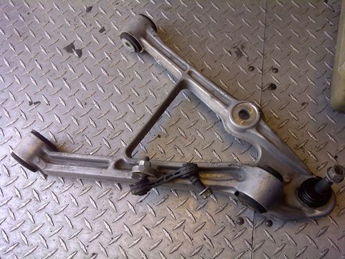
The C5 uprights are the same front to rear (they swap sides as they swap ends), but the a-arms are physically different front/rear.
C5 Front A-arms (upper then lower):

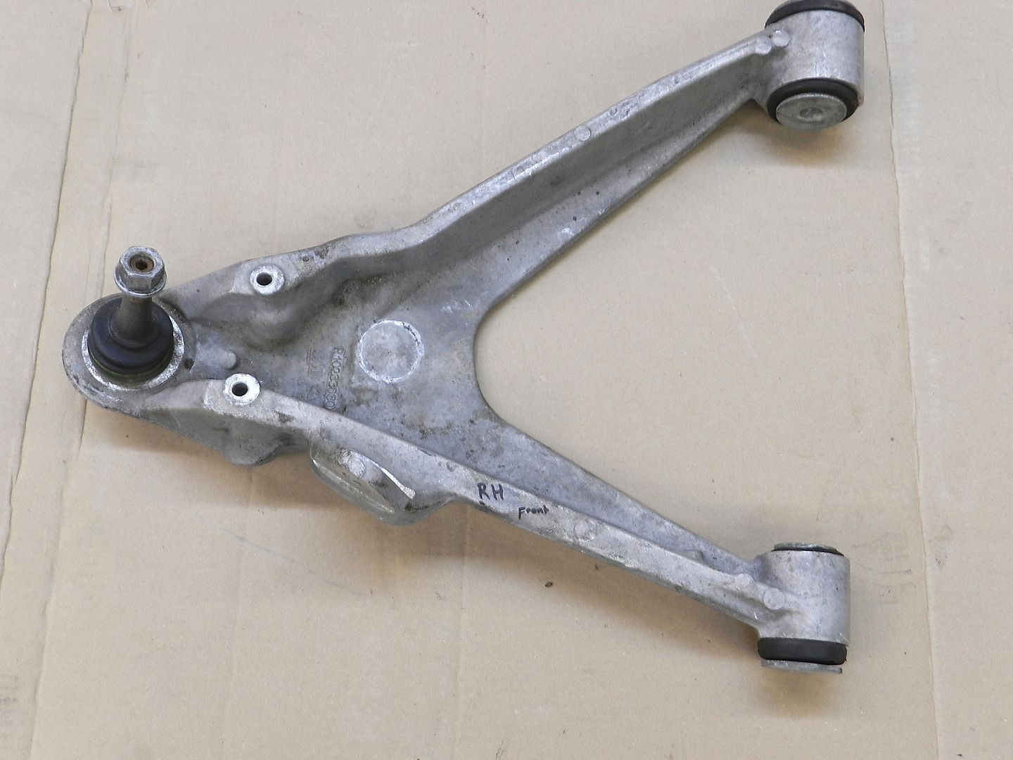
C5 Rear A-arms (upper then lower):

|
|
|
|
Bloozberry
|
DEC 02, 07:11 PM
|
|
| quote | Originally posted by bubbajoexxx:
The unit I used is the rear suspension unit of a c5 c6 not the front. The front is not suited for the rear as you suggest |
|
My mistake... for some reason I thought it was a front suspension assembly... the tie rods threw me off. Still, my goal is to convince my provincial inspection authorities (and ultimately myself) that my modifications are an improvement over the lowered stock Fiero. Swapping out the rear end for any other car's system wouldn't change what I have to do, nor make it any easier IMHO. 
|
|
|
|