
 
     |
| Blooze Own: An F355 Six Speed N* Build Thread (Page 57/126) |

|
Bloozberry
|
OCT 18, 05:15 PM
|
|
| quote | Originally posted by FieroWannaBe:
The reason the Ford GT and Ferrari F360 have less than unity camber change characteristics is becuase in straight line acceleration and deceleration, the subsequent suspension deflection will cause the tire contact patch to deform and shrink from wheel camber change. |
|
Ahh yes... sometimes I can't see the forest for the damn trees! I was concentrating on roll and overlooked considering bump at this stage. I can see how a 1:1 camber change vs roll angle would adversely affect straight-line acceleration due to squat. For lack of a better standard, I'll try to relocate the upper control arm to approximate the 0.7:1 used by the examples you gave. Thanks!
|
|
|
|
FieroWannaBe
|
OCT 19, 10:08 AM
|
|
Another consideration, for which you are already qualifying:
Keeping the lower rear attachments keeps the factory amount of roll steer, which is toe-in on compression, inducing understeer. And, the relative amount of camber change in roll from front to rear will affect cornering balance; as available grip at each end is influenced. A little more camber gain at the rear vs. the front will give the rear more available grip than the front, keeping the understeer balance.
|
|
|
|
Bloozberry
|
OCT 20, 09:57 PM
|
|
Thanks FieroWannaBe. One of the main reasons I wanted to keep the rest of the suspension points relatively stock was to keep myself from having to redesign any more than needed. As you mentioned, the shorter forward lateral link provides the correct toe change direction on the outside wheel in a turn to help counteract oversteer.
OK, so taking FieroWannaBe's advice I set the camber-to-roll ratio at 0.7:1 meaning that for every degree of body roll, the wheel camber only changes 0.7 degrees. I did that by tilting the body to the maximum 6.0 degrees of body roll I want, and then setting the outer (LH) wheel to -6.0 deg x 70% = -4.2 degrees of camber relative to the body (or equivalently 6.0 - 4.2 = 1.8 degrees tilted outwards at the top from vertical). I left the inboard (RH) wheel vertical (or at +6.0 degrees camber) since most of the weight will be off that wheel anyways, and having it flat on the ground will help marginally without impacting straight line acceleration). Then, once again I arbitrarily used the lower of the two strut-to-knuckle holes on the knuckle for the outboard upper control arm pivot point, and I set about finding the optimum length and location of the inboard upper control arm pivot.
To do that, I had to satisfy two criteria at once. The first was to make sure that at 6 degrees of roll the control arms were the same length and the pivot location was same location relative to the frame side to side even though the wheels were at very different locations relative to the body. The second criteria was that the two wheels had to return to zero camber once I rolled the body back to level. Luckily I figured out a repeatable multi-step approach to accomplish this using stick figures. 
Unfortunately the result of my first attempt at a 0.7:1 ratio had a catastrophic effect on the roll center movement. The instant center for the inboard wheel went to infinity as the upper and lower control arms became parallel to each other. That sent the roll center flying off the page.  I can post the drawings if anyone wants to see the results, but if not I'll just move onto what I came up with instead. I can post the drawings if anyone wants to see the results, but if not I'll just move onto what I came up with instead.
After studying what went wrong, I could see that I needed to get a steeper angle on the upper control arm to prevent it from going parallel with the lower control arm at any point in the range of movement. The simple solution was to move the upper control arm's outboard pivot point from the lower hole in the knuckle to the upper hole and try it again. After a few minutes of recalculating the optimum location and length of the inner pivot point, I think I hit the nail on the head.
Here is the result with the body level:

It's kind of small so for those of you with iPads the roll center while level at ride height is 67 mm above the ground.
And here are results after rolling the chassis over 6 degrees:

Keeping with the 07:1 camber-to-roll ratio goal on the outboard wheel, it ends up at -4.2 degrees, while I left the inboard ratio at 1:1 or +6.0 degrees . Amazingly, after rolling the body the roll center only rose about 3 mm vertivcally and moved away from the center line by about the same, essentially giving a stationary rear roll center. The only compromise that jumps out immediately is that the roll axis (ie a line drawn between the front and rear suspension roll centers) is practically level. This results in less weight being transferred to the front making it more likely to oversteer.
I welcome any comments or constructive criticism before I start working on the side and top views to locate the remaining coordinates.
|
|
|
|
sspeedstreet
|
OCT 21, 03:44 AM
|
|
I would be interested to see this modeled with Fieroguru's lateral link relocation kit (http://www.fiero.nl/forum/Forum4/HTML/060635.html). It would probably allow using the lower strut mounting hole for the upper link.
Neil
|
|
|
|
Bloozberry
|
OCT 21, 04:38 PM
|
|
You're probably quite right Neil. I did a quickie draft sketch to see what the impact of using Fieroguru's lateral link relocation brackets would be. I used the lower hole in the knuckle as you suggested for the upper control arm and set the camber-to-roll ratio to 0.7:1. The result was that the roll center raised to about 125mm above the ground when the chassis was level, and it migrated about 100 mm to the inside and about 20mm upwards when the chassis was rolled 6 degrees. Remember to take these with a grain of salt as I didn't do as thorough an analysis as I did earlier.
The benefit seems to be a raised rear roll height giving a more advantageous roll axis that's inclined to the rear of the car, but the trade-off seems to be a bit more roll center migration and (with all due respect for Fieroguru's design) additional cost and potentially extra component failure risk IMHO.
|
|
|
|
FieroWannaBe
|
OCT 25, 09:50 AM
|
|
| quote | Originally posted by Bloozberry:
Keeping with the 07:1 camber-to-roll ratio goal on the outboard wheel, it ends up at -4.2 degrees, while I left the inboard ratio at 1:1 or +6.0 degrees . Amazingly, after rolling the body the roll center only rose about 3 mm vertivcally and moved away from the center line by about the same, essentially giving a stationary rear roll center. The only compromise that jumps out immediately is that the roll axis (ie a line drawn between the front and rear suspension roll centers) is practically level. This results in less weight being transferred to the front making it more likely to oversteer.
I welcome any comments or constructive criticism before I start working on the side and top views to locate the remaining coordinates. |
|
After thinking a little bit about roll axis inclinations, and what they truely mean; I think in the case of a fiero it may not be so negative to have the roll axis level. Since the Fiero has a rear weight bias, the rear is already inclined to have more lateral load transfer, so the load transfer distribution is alreay biased to the rear of the car. The amount of body roll seen front and rear will become more equal, making the suspension deflection in roll more equal., However, the rear tires will be cambered closer to the road plane than the front, equating to more available grip.
If everything in the suspsnsion is tuned for understeer and not neutrality the car will always understeer, never act neutral. (which you may need if your engine were to be a hairy overpowered beast  ) )
Things I've read and pondered on the topic recently:
http://www.optimumg.com/Opt...%20Center_legacy.htm
http://www.eviltwinmotorspo...ewsletter-2006.2.pdf
and from the fordgtforum.com from the same engineer that I listened to:
| quote | I will try to add to and reinforce rather than reiterate many of the good statements and cautions here.
Traction and Stability Control- this was not required by law when the GT was designed and built. The requirement for these controls I believe happened late in 2008. The MoTec project looks very interesting- I hope it goes well!
Vehicle Physics- the laws of physics remain constant regardless of the vehicle…the REGION of physics and resultant behavior changes depending on driver control usage, the vehicle (including tire condition), ambient conditions and road surface. A vehicle’s balance depends on 5 major categories:
1- Load (vertical load on each of the 4 tires)
2-Slip Angle (the angle between the heading and the path/trajectory of the tires- typically about 3 degrees at the 4 tires at the limit on cars like the FGT) before grip flattens or falls off.
3-Slip Ratio (by percentage how much faster the contact patch is moving longitudinally versus the ground at the contact patch- 6-8% slip ratio is a typical region of max grip before it starts falling off)
4-Camber
5-Tire Properties- and how they react to the first 4 as well as weather conditions and road surface.
The vehicle’s inherent design AND the driver’s behavior with the controls (steering, throttle, brake) dictate the region the first 4 are operating and the resultant vehicle behavior.
Pass Car Balance- Understeer for sure-
Understeer (sliding the front before the rear) is stable and much more intuitive/easier. You lift off the throttle and you will regain front control- no drama.
Oversteer (sliding the rear before the front) is unstable and regaining control is much tougher and counterintuitive because lifting off the throttle transfers weight forward reducing rear grip further and making it worse- known as trailing throttle oversteer- do it over a rise, as noted in this thread, and it will be much worse due to even more vertical load off the rear tires.
However, ALL cars will oversteer with specific combinations of steering, throttle, brake, weather and road surface- hence stability control laws to try to save our ass when we venture into bad combinations of these items.
FGT chassis design understeer examples- Bruce (cobra498) noted the roll understeer at the rear on the GT- this increases rear slip angle (adding rear grip) more than the front as you push it harder (chassis rolls more). In addition, the GT has more camber gain at the rear than the front to also add more rear cornering grip as you push it harder. However, most importantly, the tire sizing and resultant properties relative to the car’s weight distribution dominates the car’s balance in a car like the FGT (especially on a steady state corner like a skid pad). We specified the tire sizing and behavior specifically to work well with the FGT inherent properties including like weight distribution.
Combined Cornering and Accel or Decel (Friction Elllipse)- A car has more pure cornering capability than it does when you add accelerating or braking. Add more throttle and your cornering ability goes down more. Opposite tradeoff for straight-line and then adding cornering.
High Horsepower but not Equal- FRONT engine, big HP cars like the GT500 have 59% front weight (vs FGT 43%) with good sized rear tires so the car has tons and tons of understeer inherently and have way less capability (acceleration and handling). You spin rear tires much earlier and easier under acceleration on a car like the GT500, so it is easier for the average person to deal with wheel spin on the GT500 with the very high understeer at much lower speed when it is breaking rears loose.
DBK’s line including “the car is deceptively fast”- I agree with this note. You are going faster and cornering harder than you think in the FGT. The car and tire properties are very forgiving at the limit, but its capability is very high. We noted this track testing with the F360 Modena. Everyone would always comment how much “faster” the F360 felt on the handling track and how much harder you felt like you were working than the FGT. However, the FGT was consistently 2 sec per lap faster than the F360 on our tiny little handling track where HP is not much of a factor. Side note- exceed the limit on a F360 Modena (with OEM tires) and you will spin faster than any other car we tested by a large margin.
Temperatures- as many noted here- below 40 deg F the tires lose considerable grip- be very careful in this region of temps or below.
Always roll into the throttle!
Scott |
|
| quote | Scott, Before you sign off,
In the post you deleted, you described how the camber would change with lowering the car. I lowered mine 1.25" up front and .75" in the rear with the single adjust T&A coilovers. Performance is fantastic ( I also went with wider, Stickier Bridgestones) but I can really see the increased negative camber as it was not changed.
As I mentioned Performance is great, Fenders not so full even with wider rubber (stock BBS upgrade wheels).
Can you spill those #s out one more time? Thanks
2112,
Must have signed off just before your note. No problem on redoing numbers.
For your example, the front camber should have gone from -0.5 deg static camber to -1.125 deg front static camber (-0.5 deg static camber + 1.25 in ride ht change x -0.5 deg/in camber gain = -0.5 deg + -0.625 deg = -1.125 deg front static camber give or take a tenth or so for build and ride height adjustment tolerance)
.
The rear camber should have gone from -1.5 deg static camber to -2.06 deg rear static camber (-1.5 deg static camber + 0.75 in ride ht change x -0.75 deg/in camber gain = -1.5 deg + -0.56 deg = -2.06 deg rear static camber give or take a tenth or so for build and ride height adjustment tolerance).
So you should have been very close to maintaining the stock camber split of -1.0 deg more at the rear, which would keep the same balance as designed.
The more negative camber will give you noticeably more cornering grip along with your wider Bridgestones (which have more grip than base to begin with). The downsides to more camber are typically a little less straight-line performance, more inside edge tire wear on the street and more truck rut following yanking the car around a little more and less full looking fenders.
You can go back to stock cambers and fill the fenders out more and still have better cornering and straightline performance than stock due to the wide stickier Bridgestones and lower Center of Gravity height due to lowering. And then good tire wear and rut following.
Note the rear tire clearance package is tight when the stock car is pushed to the limit...especially on a track with banking. It is tightest to the clamshell. Take a look at your clamshell for witness marks after aggressive driving. No witness marks...let'r rip! But I would check it periodically with those bigger tires, especially if you go back to stock static camber.
Hope this all helps.
Scott |
|
| quote | Jason,
Understood on your caster and lack of shims at the front lower pivot. Lowering the car 1” at the front should have increased caster just under 0.5 deg. So between manufacturing tolerance and lowering the car your static caster makes sense. I don’t think this should be too significant and there is not much you can easily do to adjust it with the lowered car. You are just at a new point on the kinematics curve with the lower car. You may be able to adjust the caster back with shims at the upper arm, but I am not sure you will have the adjustment there depending on shims and camber. You could also shim the other 3 pick up points (Both uppers and rear lower) out to achieve the caster, effectively increasing track and reducing fender clearance causing another possible problem. Probably not worth it.
Pros and Cons
Like almost everything, you rarely get something for nothing. There are some pros and cons of having more caster than stock. (Yours is reasonable though, the following is more for guys to think about as cars are modified.) One potential pro the guys mentioned was a little more camber with steer angle, however, this will be very small even at high steer angles and actually may be negated by the fact that the caster trail has increased a little as well. Caster trail is the effective fore-aft lever arm distance from the imaginary caster intersection with ground and the fore-aft distance to the wheel center on the ground. This is 28.5 mm stock on the FGT and it looks like just over 34 mm on your left front.
More caster will give you a little more straight line stability on a smooth road. However, more caster can also give you more wheel fight on bumpy or truck rutted roads. Have you noticed a difference in wheel fight or truck rut following since before the car was lowered? However, increased static camber with lowering would also make these worse and likely a bigger factor depending on your static camber settings.
In addition, increasing caster increases caster trail as noted, which will tend to reduce the change in steering torque felt as you approach the limit. Therefore, higher caster trail typically means it is a little harder to sense the limit in the steering wheel torque. This is something to worry about on higher caster changes (+1 deg or more), but I think you should be OK at your current settings.
I can give you more detail on this geometry and kinematics stuff if you would like.
Scott |
|
Sorry for the long post, I thought some more insight, and some from a practicing SME, might be good reinforcment for you design direction.
|
|
|
|
FieroWannaBe
|
NOV 16, 12:17 PM
|
|
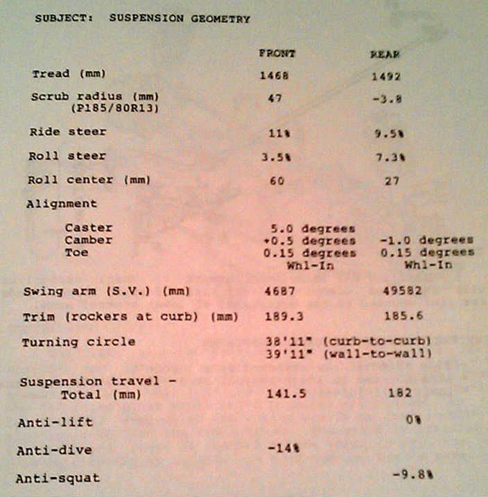
I found some information that would have been more helpful to you when you where making you rmeasurements/drawings of the stock suspension.
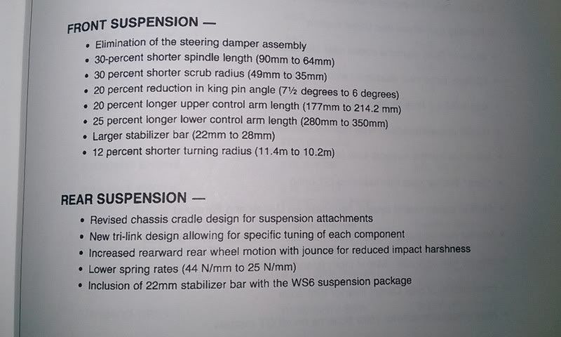
And to compare to the 1984 models:
|
|
|
|
Bloozberry
|
NOV 16, 12:55 PM
|
|
|
Thanks FieroWannabe! I meant to thank you earlier for your second to last post above too, but obviously got sidetracked. I haven't posted in a while, but I've been working up the upper frame rail, strut tower, firewall and trunk sheet metal drawings, as well as the pushrod coilover geometry over the last couple weeks. Things are coming together quite nicely and I'm nearly ready to post my progress. My design will differ from Datsun1972's in some key areas.
|
|
|
|
Bloozberry
|
NOV 24, 10:25 PM
|
|
I left off with my second to last post thinking I would draw the side and top views of the new upper control arm to finish locating it in three dimensions, but quickly ran into a few roadblocks. The first thing I realized was that I needed to work out the basic location of the new pushrod shock system so as not to interfere with the upper control arm mount. Easy enough I thought... except that to design the pushrod shock system, I needed more details about the structure of the existing frame to make sure the shock and bellcrank mounts could be located in areas of sufficient strength. One step forward, two steps back.
Some of you may recall I measured and drew out the lower frame rail, strut tower, and cradle assembly earlier on, so I "simply" added the upper frame rail, rear cabin structure, and rear upper frame cross member to those drawings. The convoluted shape of the rear cabin structure was the most difficult to measure but I took a page from Yarmouth Fiero's thread and used a single axis laser to give me a straight and level reference line from which to take measurements. I moved it about and changed the orientation to suit my needs. (I apologize for the crappy picture but I had to turn off the camera flash so the laser beam wouldn't be washed out)

Since the rear quarters of the F355 body are already mounted to my '88 frame, I took as many measurements as I could from my '85 parts car frame instead. The only differences are in the strut tower, so I was able to get most measurements directly from the '85. These next three drawings will form the basis for the design of the upper control arm mount and the push rod shock system.
I color-coded the various main structures in the drawings to make the spaghetti of lines more understandable in some of the views. The upper frame rail is in blue, the lower in green, the main cabin structure in red, and the strut tower using bolder black lines than the rest of the components. It's pretty obvious in the top and side view drawings but the colors really help discern what's going on in the rear view drawing. 3D CAD would be really useful here.

The side view drawing (above) shows most of the main structures of the rear chassis quite well, namely; the upper and lower frame rails, which are bridged vertically by the strut tower at the mid point, and by the cabin firewall at their forward points. The upper frame rails are bridged across the car in several locations including the rear-most upper cross member, the strut tower brace, and the upper cabin cross member (all shown in cross section). Finally, the lower frame rails are bridged across the car by the rear bumper (not shown), the rear cradle cross member, and the lower cabin cross member.
Here are the top and rear views:


After having gone through this exercise, it bcame clear that there wasn't much structure aft of the strut towers to mimic Datsun1972's rearward oriented shocks. In fact, much of the structure aft of the strut towers has been deliberately weakened with large holes by the factory to serve as crumple zones in the event of a collision from behind. There being far more structure ahead of the strut towers, I decided to work on a design that would see the shocks run forward toward the cabin. I felt the proximity of the upper and lower rails, plus the cabin upper and lower cross members all located within a reasonable distance of each other at the rear cabin wall would provide ample opportunity to triangulate some rectangular tubing to form the forward shock mount. The other benefit is that by locating the shocks in the engine bay rather than the trunk, the coilovers could bookend the engine quite nicely, peeking out from under the sail panels.
More on this soon.
|
|
|
|
Yarmouth Fiero
|
NOV 25, 05:38 AM
|
|
Very nice work Blooz. I wish I was standing there jotting down your measurements as you take them so I could add them to my chassis Rhino model.
I've been toying with the idea of having a series of lasers located around the shop shooting perpendicular lines on the chassis...... but I think they may freak Rosie (the dog) out too much. ha-ha-ha. Also, I wish I had heat in my shop. I have had the engine cradle in my dining room for a while now taking accurate measurements but apparently I'll soon be evicted to make room for the Christmas tree. 
Interesting development with the suspension design. Looking forward to more posts regarding this process.
|
|
|
|