 
     |
| NS F355 Project (Page 51/73) |

|
Yarmouth Fiero
|
OCT 09, 07:51 AM
|
|
|
Having read your comment again Blooz, perhaps having the drive belt assembly fastened to the engine/ gear mounts and let it all move as one unit and then have a traditional drive shaft with CV and tripot as the output shaft to the wheels. It would eliminate the input shaft completely and get the whole assembly tucked up close to the gearbox. I found a nice 3D model of an Audi gearbox but the drawing is a little too expensive for a "what if" design exercise.
|
|
|
|
Bloozberry
|
OCT 09, 12:51 PM
|
|
| quote | Originally posted by Yarmouth Fiero:
Having read your comment again Blooz, perhaps having the drive belt assembly fastened to the engine/ gear mounts and let it all move as one unit and then have a traditional drive shaft with CV and tripot as the output shaft to the wheels. |
|
Yes... that's what I tried to explain in my post above.  The other thing you'd need to find is a transmission where the output shafts were far back enough to give you the forward room to add the two gears and belt system and still have the axle fall where you want it. The other thing you'd need to find is a transmission where the output shafts were far back enough to give you the forward room to add the two gears and belt system and still have the axle fall where you want it.
|
|
|
|
Yarmouth Fiero
|
OCT 09, 12:59 PM
|
|
Yes, I agree, there are a number of different gearbox models to choose from. I based my basic drawing on the Audi 016 that Don had sent me. From there it was close to 12" between sheaves and the first iteration gave me 4 1/4" dia sheaves and a 62mm wide belt. It seemed like a good place to start and it was very close to what I needed.
Edit to add. I do have the flexibility to move the engine fwd or aft a little so suit the belt length / location. The first iteration gave me three possible belt/ sheave combinations to handle the load.[This message has been edited by Yarmouth Fiero (edited 10-09-2014).]
|
|
|
|
355Fiero
|
OCT 09, 01:09 PM
|
|
Graham;
I am surprised that the assembly is so far back? I don't doubt your measuring and placement, it was just a surprise that it was back that far. Is there a way to move the engine froward so that the crank harmonic balancer is up against the firewall area and cut into the firewall? Perhaps, if you are set on an SBC (they are quite large), then staying lateral would be a lot less work and more reliable in the long run..... I just think of the Audi V8 engine man is doing and his setup looks like with the 3" stretch, it would be almost perfect placement.
Interesting design thoughts though. I am looking forward to seeing what you end up in the end.
Cheers
Don
Edit: Also as Blooz said, solid mounting the belt drives to the engine/trans setup or to the frame and then having CV joints on both ends of a longer axle shaft would also be a better arrangement in my opinion.[This message has been edited by 355Fiero (edited 10-09-2014).]
|
|
|
|
Yarmouth Fiero
|
OCT 09, 01:51 PM
|
|
|
Hi Don, thanks for the input. The engine is back quite a distance for sure. I am not sure if the engine intake can be swapped around although I suspect it can, but just in case, I left room for intake ducting. The belts do come in shorter lengths, infact almost half as short as I have shown. Last night when I was doing this drawing, I just sort of picked a belt and drew it. I'll refine the whole arrangement tonight and post an update as per the suggestions today.
|
|
|
|
fieroguru
|
OCT 09, 04:51 PM
|
|
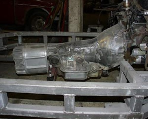
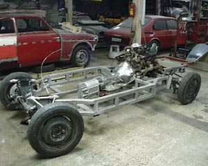
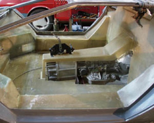
The use of belts to get the drive back to the axles has been done before... I just can't find the picture. The pulleys came off a RWD rear end that was shortened to be just a pumpkin. I am sure it was in a replica of some kind.
Here are some other fun pictures to get the creative juices flowing:
|
|
|
|
Yarmouth Fiero
|
OCT 09, 07:59 PM
|
|
Thanks for the pics Fieroguru. That is certainly an interesting gearbox arrangement. I have seen a belt drive before too but I can't for the life of me find it online. I seem to recall it was a dragster.
I double checked my gearbox dimensions and they are pretty close to the Audi 016. As I mentioned, I can move the engine forward a little more to get it tucked behind the firewall. I just need to find a different style intake. I changed the shafts so that the belt drive is tucked in close to the engine/ gearbox. This will facilitate mounting it all together in some fashion. I then stretched out the drive shafts to make them more functional.


|
|
|
|
Bloozberry
|
OCT 09, 09:35 PM
|
|
That's more like it. I'll be curious to see how you design the cradle... lots to consider!
Edit to add: Looks like you'll need a remote filter kit![This message has been edited by Bloozberry (edited 10-09-2014).]
|
|
|
|
Yarmouth Fiero
|
OCT 10, 07:21 AM
|
|
You have a keen eye Grasshopper. I'll probably just get a filter notching kit. 
With regard to cradle design, I may end up with a cradle within a cradle. I am going to do more research on SBC intakes and see what is available for reversing the intake. I saw another build that has an intake that sweeps around the distributor. If I can move the engine forward another 4" then I can get down to a 8" center to center belt/ sheave arrangement which I think would be easier to design around. That will save me the cost of the filter notching kit. 
TGIF
|
|
|
|
fieroguru
|
OCT 10, 07:47 AM
|
|
What intake were you planning to use? The LT1 has been flipped numerous times and just requires building up the seal flange on the ends, but you will have to run distributor less.
I flipped the upper plenum on a modified Holley Stealth Ram intake (see Trintens SBC/F23 build in the construction zone)... lots of work, but works.
Archie also flipped the upper plenum on a TPI intake and extended the TB mounting point to clear a crab dist.
|
|
|
