|
| LS4 / F40 swap - fieroguru (Page 50/216) |

|
fieroguru
|
OCT 14, 04:34 PM
|
|
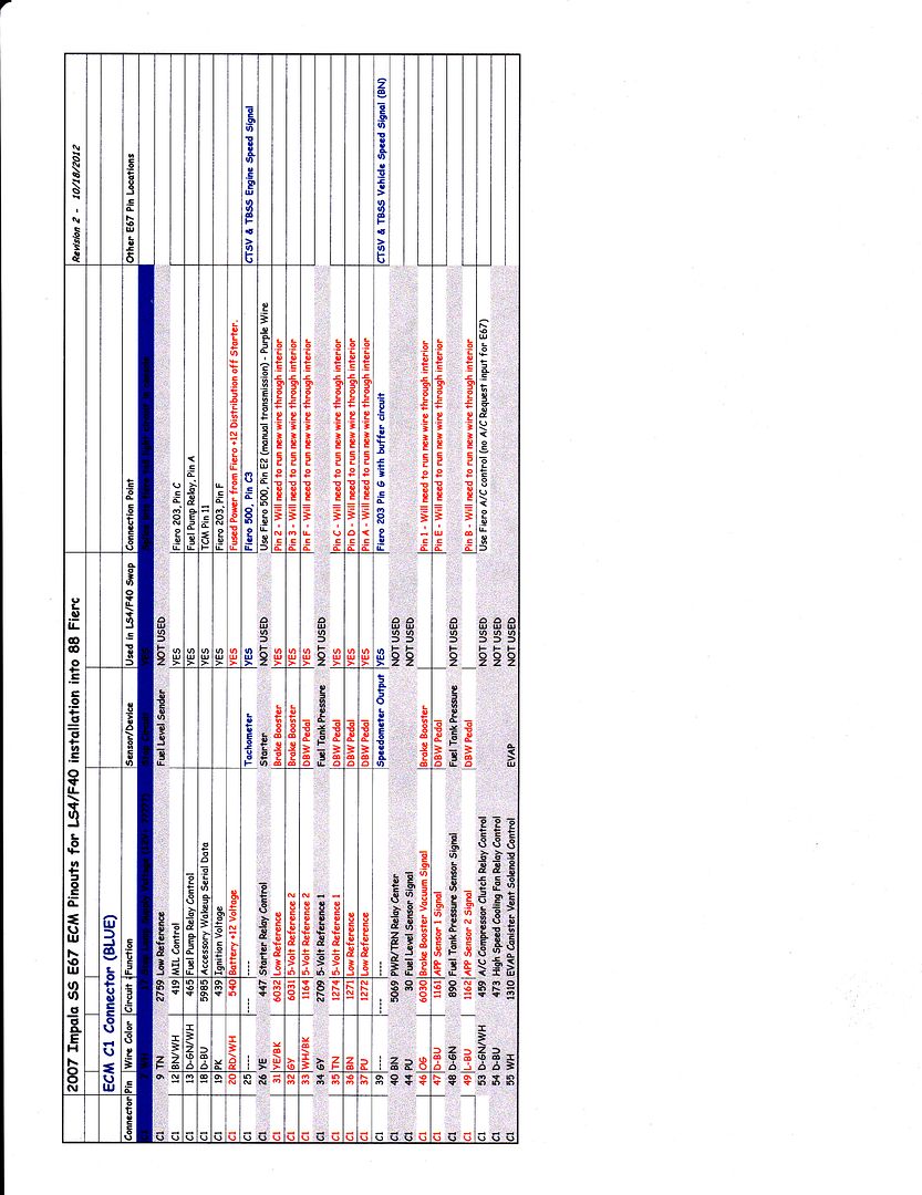
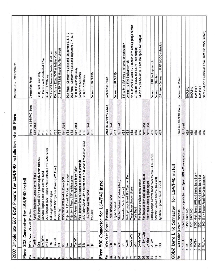
Spent most of the day documenting the wire/circuit/sensor terminations for all the ECM connectors and the Fiero 203/500 specific to this swap. As I decide what to keep/omit, I wanted to know what all te inhibitors were for DoD activation. Here is a list:
1. Engine manifold vacuum low
2. Brake booster vacuum pressure low
3. Accelerator pedal position rate of increase too high, electronic throttle control
4. Accelerator pedal position too high, electronic throttle control
5. Ignition voltage out of range
6. Engine oil pressure out of range
7. Engine oil temperature out of range
8. Engine RPM out of range
9. Transmission gear incorrect
10. Transmission range incorrect
11. Transmission gear shift in progress
12. All cylinders activated via scan tool output control
13. Minimum time in V8 mode not met
14. Maximum V4 mode time exceeded
15. Engine oil aeration present
16. Decel fuel cutoff active
17. Fuel shut-off timer active
18. Minimum heater temp low, HVAC system
19. Reduced engine power active, electronic throttle control
20. Brake torque management active
21. Axle torque limiting active
22. Engine metal over temperature protection active
23. Catalytic converter over temperature protection active
24. Piston protection active, knock detected
25. Hot coolant mode
26. Engine over speed protection active
27. Fault active or Fault Pending - cylinder deactivation is disabled for the following faults:
*** Brake Booster Vacuum Sensor
*** Manifold Absolute Pressure Sensor
*** Engine Oil Pressure Sensor
*** Engine Coolant Temperature Sensor
*** Vehicle Speed Sensor
*** Crankshaft Position Sensor
*** Engine Misfire Detected
*** Cylinder Deactivation Solenoid Driver Circuit
As you can see the DoD setup is quite finicky and everything has to be in the programed ranges for it to work. Now as I try to get the system to work with a manual transmission, these are my 4 biggest concerns.
9. Transmission gear incorrect
10. Transmission range incorrect
11. Transmission gear shift in progress
*** Vehicle Speed Sensor
All communication about the transmission (Gear, Range or mid-shift) only happens through the High Speed GMLAN Serial Data Bus and there are no traditional inputs to the ECM for these. So if I need to fake the ECM into thinking it is in Drive, and 4th gear is engaged, then all that trickery has to happen on the TCM.
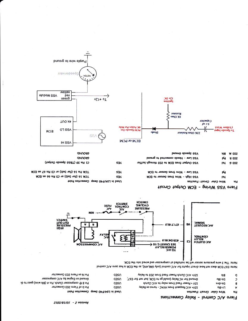
My concern about the VSS is that the two VSS wires go to the VSS and only a single VSS wire goes from the TCM to ECM (stock E67 LS4 calibration). Many other swaps using the E67 in a manual configuration were able to run both VSS wires directly to the ECM and get the Speedo to work, but the vehicle speed within the ECM (from a scanner) wouldn't show vehicle speed. The concern is if the ECM doesn't show the vehicle speed, will it enable DoD, or is it even looking for the VSS approval from the ECM, or does it come from the TCM through the High Speed GMLAN Serial Data Bus...
Probably the safest bet it to plan on installing the TCM in the center console area...
|
|
|
|
dobey
|
OCT 16, 05:27 PM
|
|
| quote | Originally posted by fieroguru:
My concern about the VSS is that the two VSS wires go to the VSS and only a single VSS wire goes from the TCM to ECM (stock E67 LS4 calibration). Many other swaps using the E67 in a manual configuration were able to run both VSS wires directly to the ECM and get the Speedo to work, but the vehicle speed within the ECM (from a scanner) wouldn't show vehicle speed. The concern is if the ECM doesn't show the vehicle speed, will it enable DoD, or is it even looking for the VSS approval from the ECM, or does it come from the TCM through the High Speed GMLAN Serial Data Bus...
Probably the safest bet it to plan on installing the TCM in the center console area... |
|
The E67 manual swaps you refer to are DoD/AFM-free swaps I presume, and don't have TCMs? Or have other people swapped in DoD engines with manual transmissions somewhere that I haven't seen yet? Would like to see more information on them if so.
Are you planning to use the 4t65e TCM from an LS4 car, or some other solution that could actually determine gear from speed/load/etc… inputs based on programming of gear ratios from the trans, and tire size?
|
|
|
|
fieroguru
|
OCT 16, 06:19 PM
|
|
| quote | Originally posted by dobey:
The E67 manual swaps you refer to are DoD/AFM-free swaps I presume, and don't have TCMs? Or have other people swapped in DoD engines with manual transmissions somewhere that I haven't seen yet? Would like to see more information on them if so.
Are you planning to use the 4t65e TCM from an LS4 car, or some other solution that could actually determine gear from speed/load/etc… inputs based on programming of gear ratios from the trans, and tire size? |
|
Correct. There are no E67 applications with DoD/AFM and a manual transmission, and no known completed manual swaps that kept DoD... I am a glutton for punishment.
I am planning to keep the stock 4T65e-hd TCM to start with. The crazy idea I have is to hardwire the TCM inputs so the TCM thinks its in Drive (at shifter) and in 4th (actual drive gear) and then let the VSS speed change. Might play with some bulbs and resistors to get everything to be correct for these parameters as that is what DoD is looking for. So my trigger for DoD will largely be RPM and VSS driven (given MAP and all the other factors are in range). If I restrict the RPM to be between 1600 and 2300 and the vehicle speed to be above 55 mph, then from 55 to 65 DoD would work in 5th or 6th gears and from 65 to 79 it would only work in 6th. My goal with the manual setup is to only have DoD function at highway/interstate speeds... mainly because it will sound like crap in 4 cyl mode with my loud exhaust, and I want it to sound good while tooling through town...
I still need to document all the TCM pin locations and resistance values for all the solenoids and pressure/temp sensors to see what my options are.[This message has been edited by fieroguru (edited 10-16-2012).]
|
|
|
|
fieroguru
|
OCT 16, 06:24 PM
|
|
|
|
|
Jims88
|
OCT 16, 09:16 PM
|
|
Ohhhhhh...............thats not helpful...............THATS FREAKING AWSEOME!!!!!!!!!!!!!!!!!!!!!!!!!!!!!!!!!!!!!!
Thank You fieroguru!
|
|
|
|
fieroguru
|
OCT 18, 06:49 PM
|
|
I updated the wiring documents above, so if you save them already, you probably want the revisions (added the DCL connector and updates lots of info in the other connectors).
The electrical circuit side is one of my weaknesses... so as I look at what I can do to fool the TCM into thinking the 4T65e-hd is still present and working, I am taking a rather simplistic approach... and likely doing some things wrong. Any TCM circuit experts feel free to provide other suggestions.
The major unknown right now is how much of the TCM functions have to be correct in order for the TCM to give the ECM the go ahead for DoD activation. So at this point I am planning to error on the side of doing too much (I can always remove them later) vs. not doing enough and having to revisit the issue. The chart below has the majority of my thoughts/plans, but a high level plan of action:
1: Hard wire the inputs from the Range Selections so the TCM see's the transmission in DRIVE
2: All solenoid circuits wired up with fiero side marker light bulbs so they will see a load.
3: Wire up the fluid Temp with a resistor so the TCM thinks the transmission is at about 175 degrees
4: Connect all the normal wires between the TCM/ECM and external inputs as normal
Once those are done, I am down to two issues.
The VSS could be connected from the F40 to the TCM.... But then the TCM will see the 60Kppm vs 24K... Might just add a 30 tooth reluctor on the tripod housing or intermediate shaft (unless I can just progam the TCM to look for the 60K ppm input).
The ISS... only way to mimic this signal is to add a reluctor to the transmission input shaft... which won't be easy. I could added it to the engine crankshaft (possibly mill the OD of the flywheel or bolt it on the balancer), but not sure if the TCM will go nuts with the ISS seeing speed while the VSS is stationary (when stopped and the clutch in). The only time the 4T65e-hd sees this in Park/Neutral, but the TCM will not see the transmission in Park/Neutral).
Here is the updated TCM wiring details (the items in Blue are the items I am still working on - ISS, TCC unlock confirmation, Stop light input):
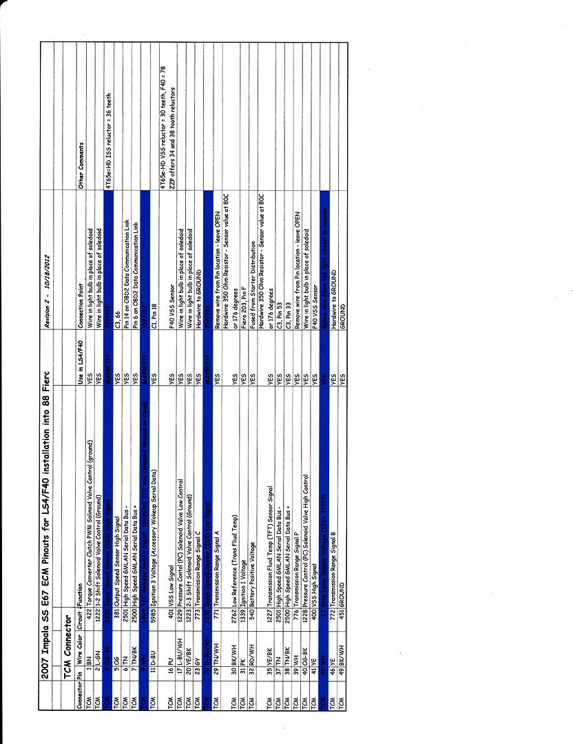 [This message has been edited by fieroguru (edited 10-18-2012).]
|
|
|
|
fieroguru
|
OCT 20, 07:00 PM
|
|
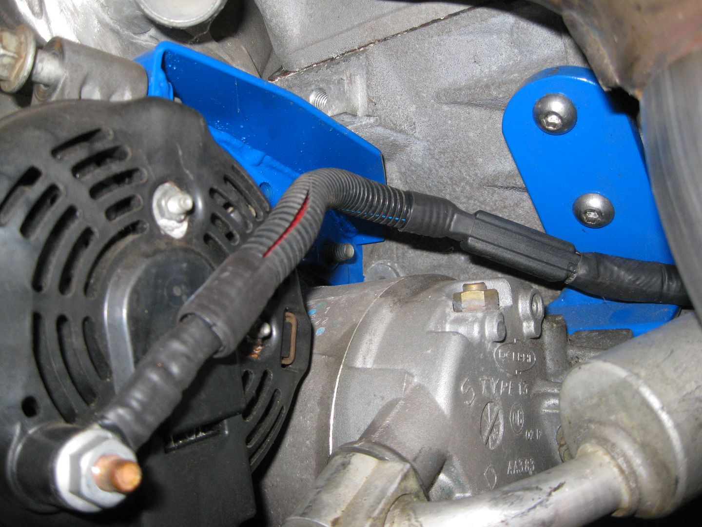
Getting closer to having the engine side of the harness done...
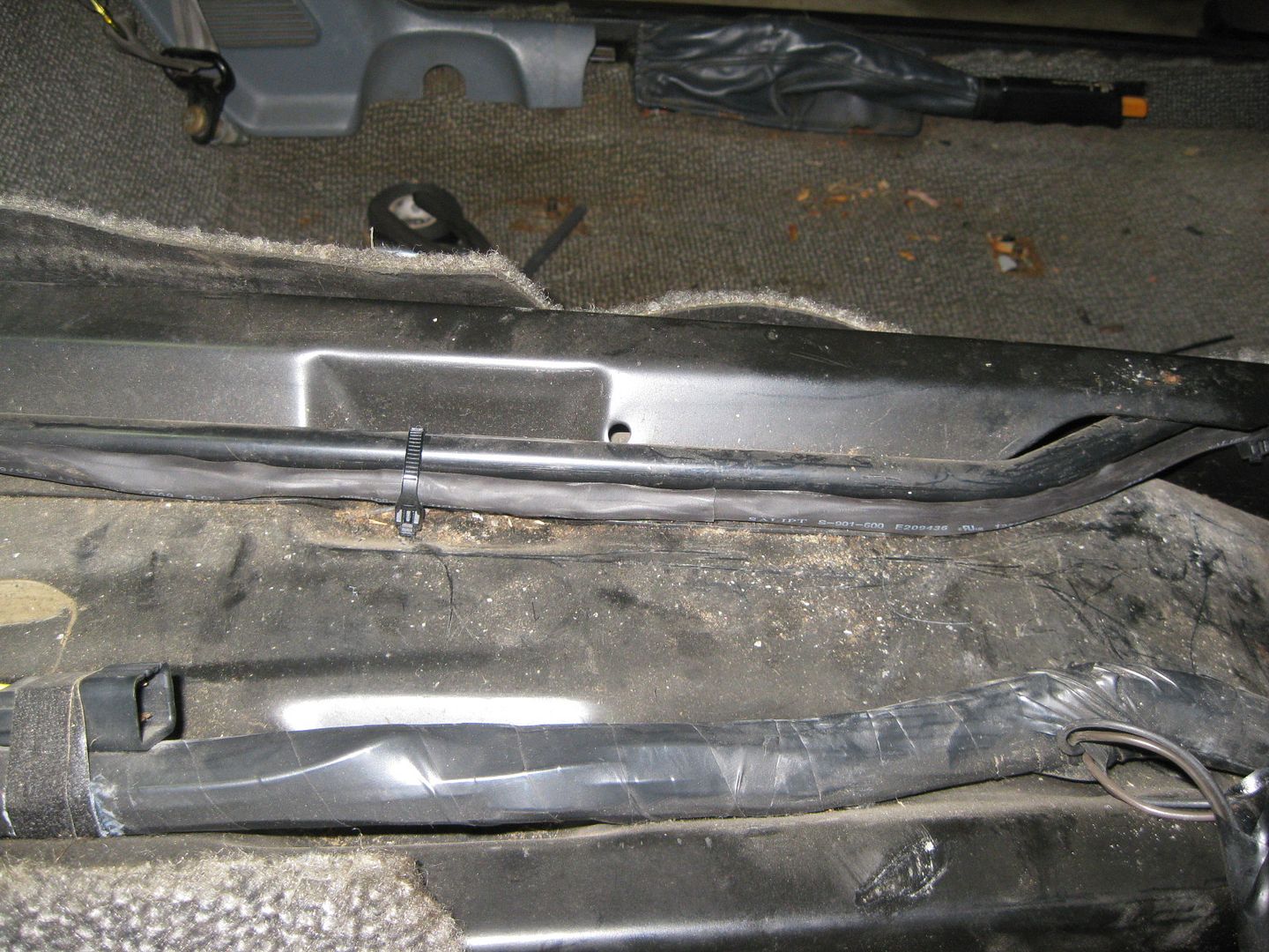
Hopefully on Sunday I will add in the A/C pressure sender and loom up the front harness containing the Alternator, A/C clutch, A/C pressure switch, Ground to engine, B1 Knock, Fiero Oil pressure sender and finish up the engine side of things. The wire bundle across the exhaust manifold is the portion of the harness that will enter the center console area (500, 203, TCM and A/C & fuel relay will all be in the center console area). I still need to add in the wires for the throttle pedal, brake booster sensor and the ones to the TCM.
Re-pinning the terminals at the ECM takes a special crimp tool.
The professional version costs about $300,
The one from LSxTune is about $32, http://www.lsxtune.com/shop..._170/products_id/362
This one from radio shack is $9.99 and the one I have been using so far (ordered the LSxTune one as well):


I also found on the truck forum where they were tricking the T42 TCM's shift solenoids with a 1K resistor when swapping in a 4T80 (it had 1 less shift solenoid) so that is promising. They also had other swaps with the T42 TCM where they swapped in a transmission w/o the ISS sensor and were able to tune it out. I still need to check on some things. I may add a 2nd VSS sensor to the transmission and point it at the output shaft gear (22 tooth pinion that drives the 78 tooth ring gear). The 22 would be close to the 25 the TCM is looking for and may be close enough to make adjustments in the tune. Now I need to see if there is a good spot on the case to drill through to mount the sensor.
|
|
|
|
fieroguru
|
OCT 21, 03:16 PM
|
|
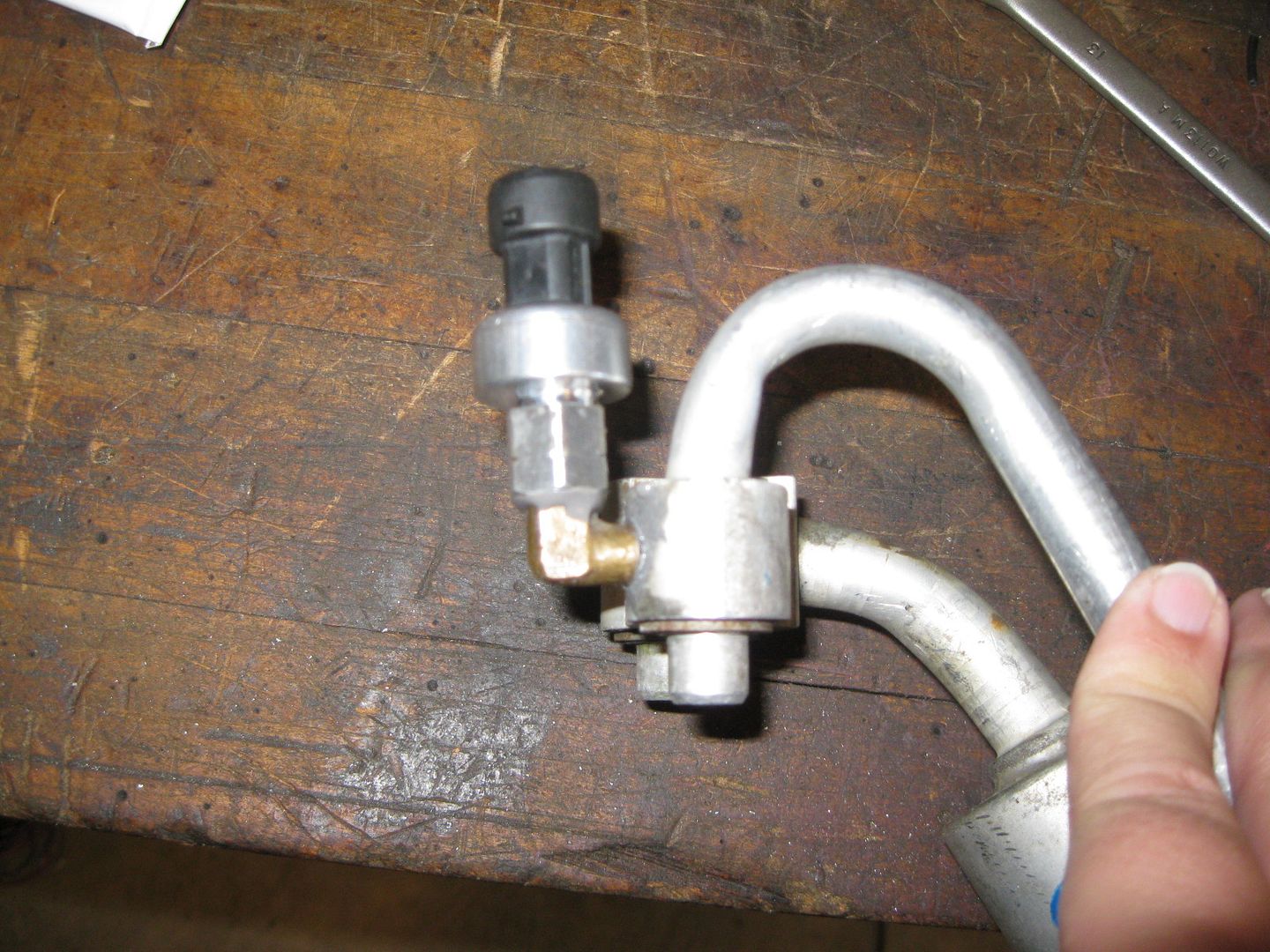
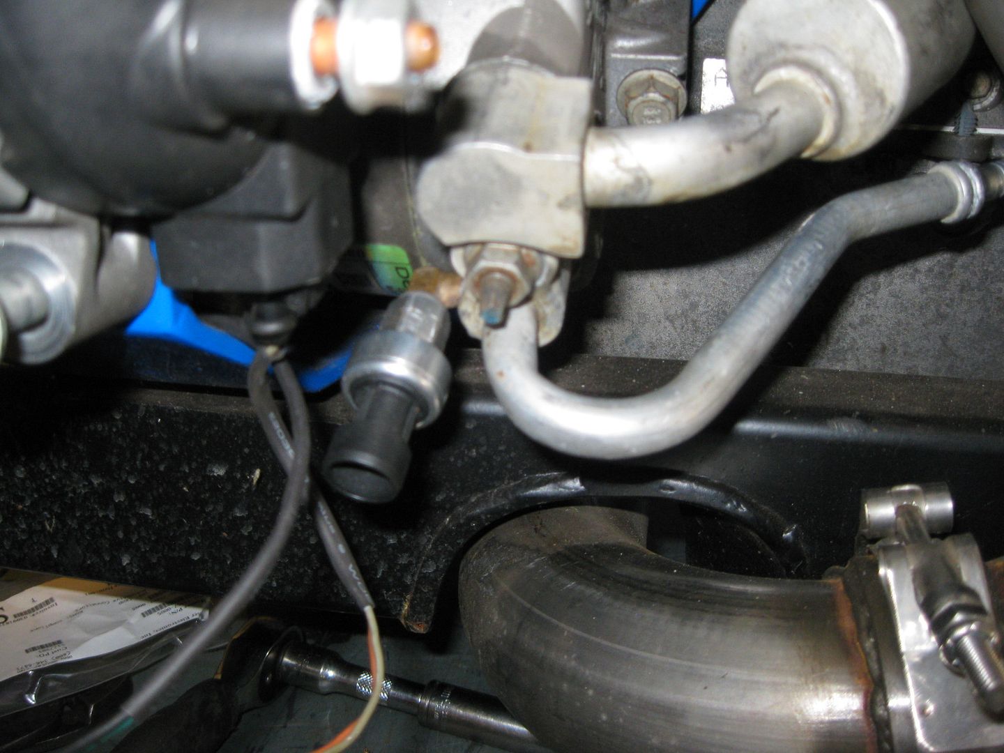
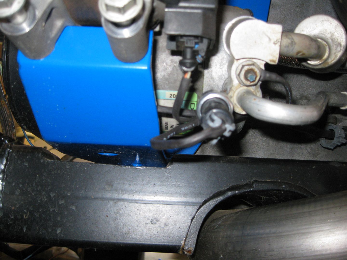
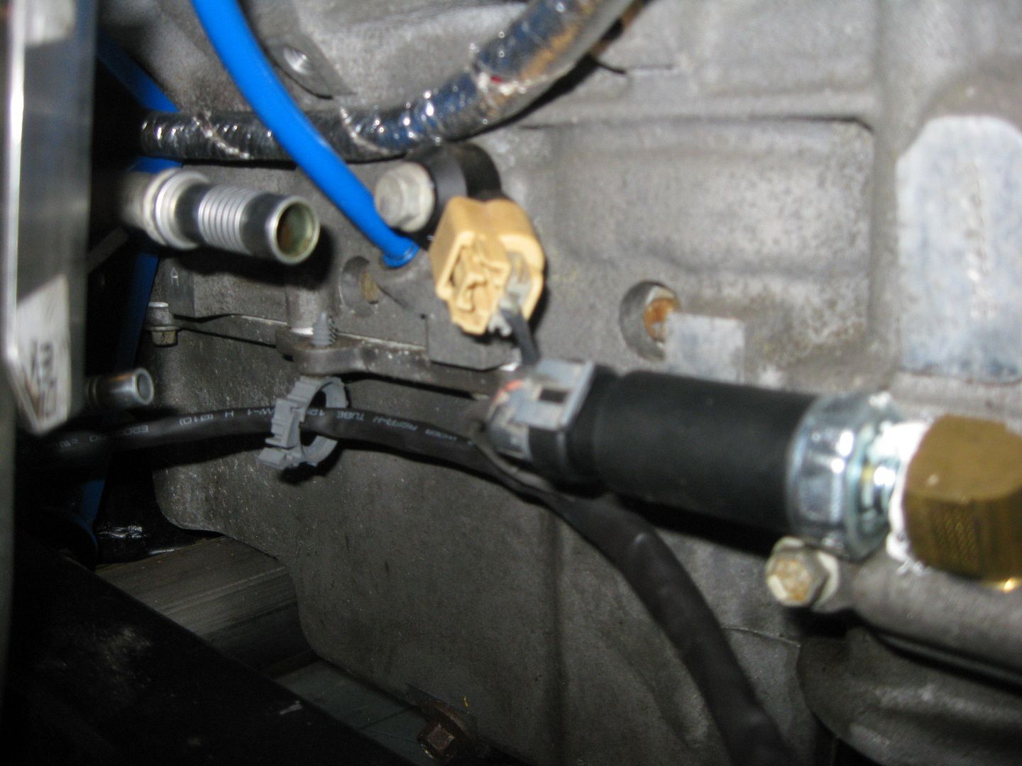
Installed the A/C pressure sender for the ECM. Found a brass fitting with a 1/8 NPT on one end and used a M10-1.5 die to rethread the other end. Then it was a matter of drilling/tapping the high side fitting at the compressor. I coated the threads with JB-Weld before threading them in to help ensure a leak free seal.

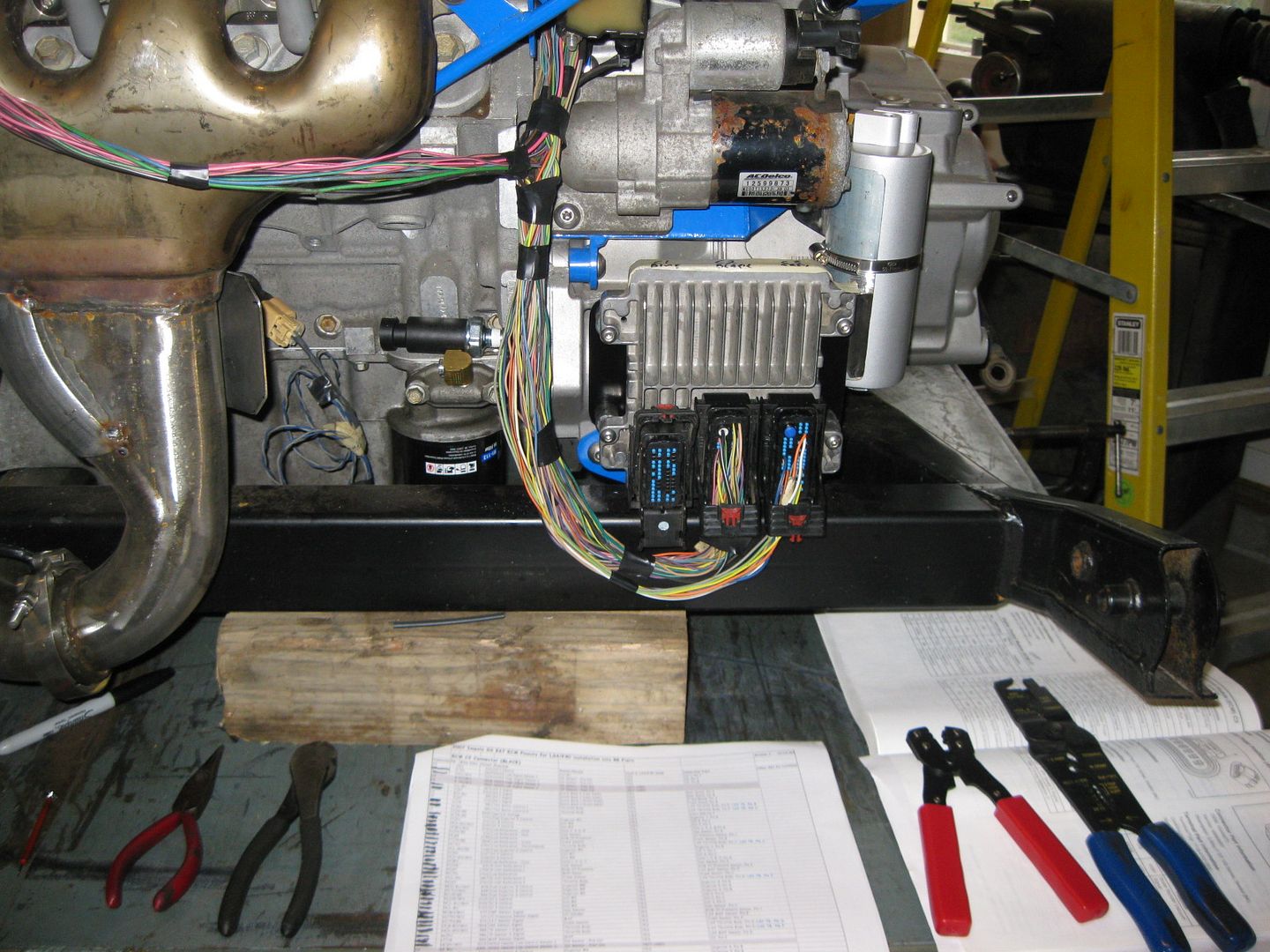
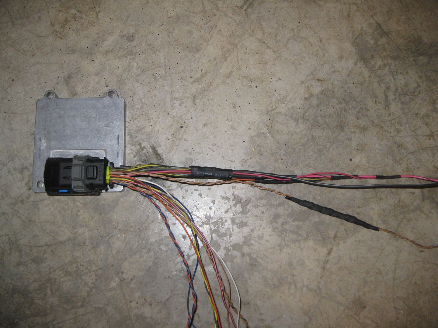
With the last engine sensor installed, I finished up the engine harness (except soldering on the starter terminal end):
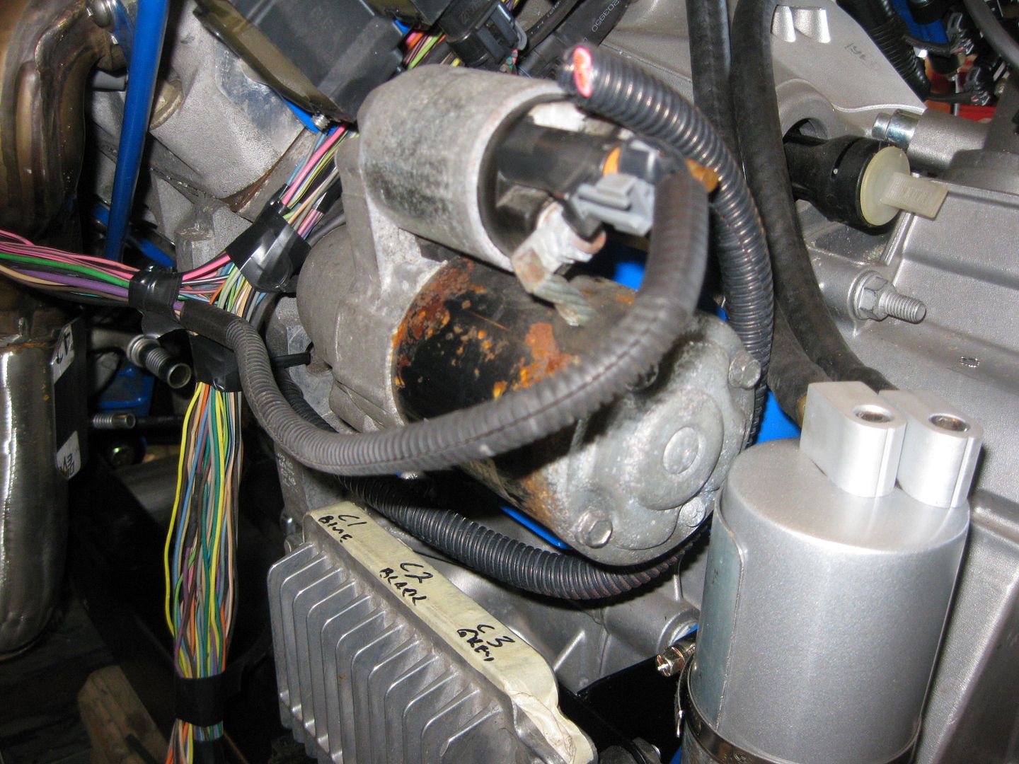

The center connector on the ECM is now fully compete. The other two still need quite a few wires from the other various components that will be in the console/foot well/brake booster area.
Next step is to reinstall the engine/transmission in the chassis and continue to finalize the wiring, fuel filter location, build the fuel line and mockup the coolant hoses. Then everything will come out again to finalize the engine bay.
|
|
|
|
fieroguru
|
OCT 27, 07:38 PM
|
|
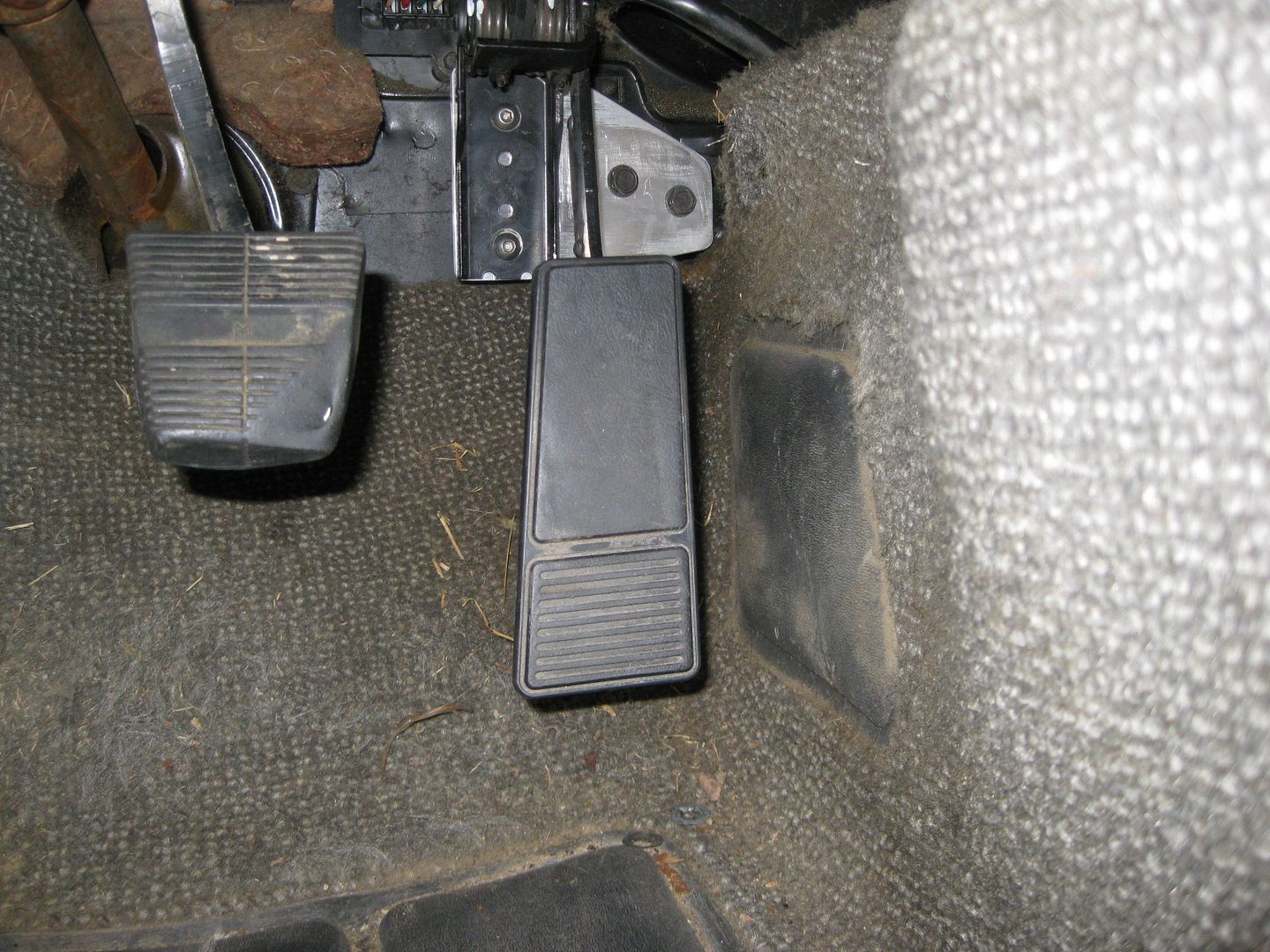
DBW throttle pedal is now installed. I fabbed up an aluminum bracket to mount the pedal to, then the aluminum bracket bolts to the stock fiero pedal mount. This allows the pedal to be slide to the drivers side enough to clear the brake booster vacuum tube. All I need to do for this was remove the plastic mounting block that comes with the throttle pedal (this block is also the primary throttle stop).

Since I removed the primary throttle stop, I welded on a new one. It is just some 3/16" steel the proper thickness welded to the backside of the throttle pedal arm so it will bottom out against the aluminum bracket.
Stock fiero throttle mounting bracket:

DBW pedal installed:

I also started on the interior jumper harness for the DBW pedal and Brake Booster sensor. It will have a 3 wire connector for the booster sensor right by the pedal assy. The other end will have a 10 pin connector (3 wires for sensor, 6 wires for pedal). This way I can removed the interior harness when needed and the engine side will have the other side of the 10 pin connector. Should finish this sub harness up on Sunday.
|
|
|
|
fieroguru
|
OCT 28, 04:27 PM
|
|
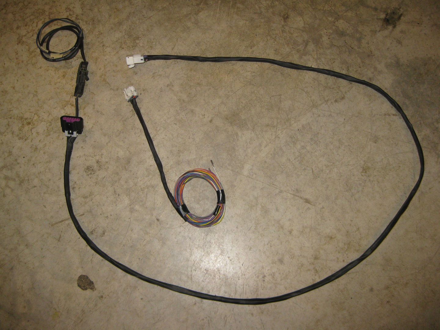
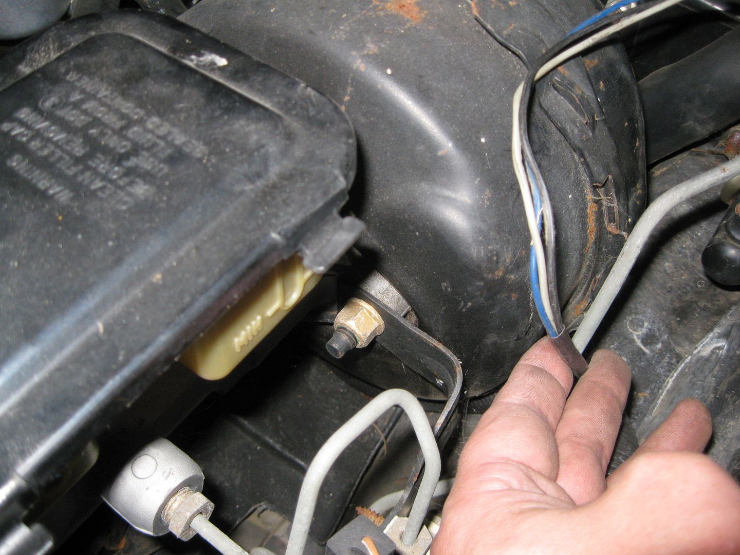
Finished up the jumper harness for the throttle pedal and the brake booster sensor:
Drilled a hole in the plastic HVAC panel right by the C100 connector for the brake booster harness to pass through:
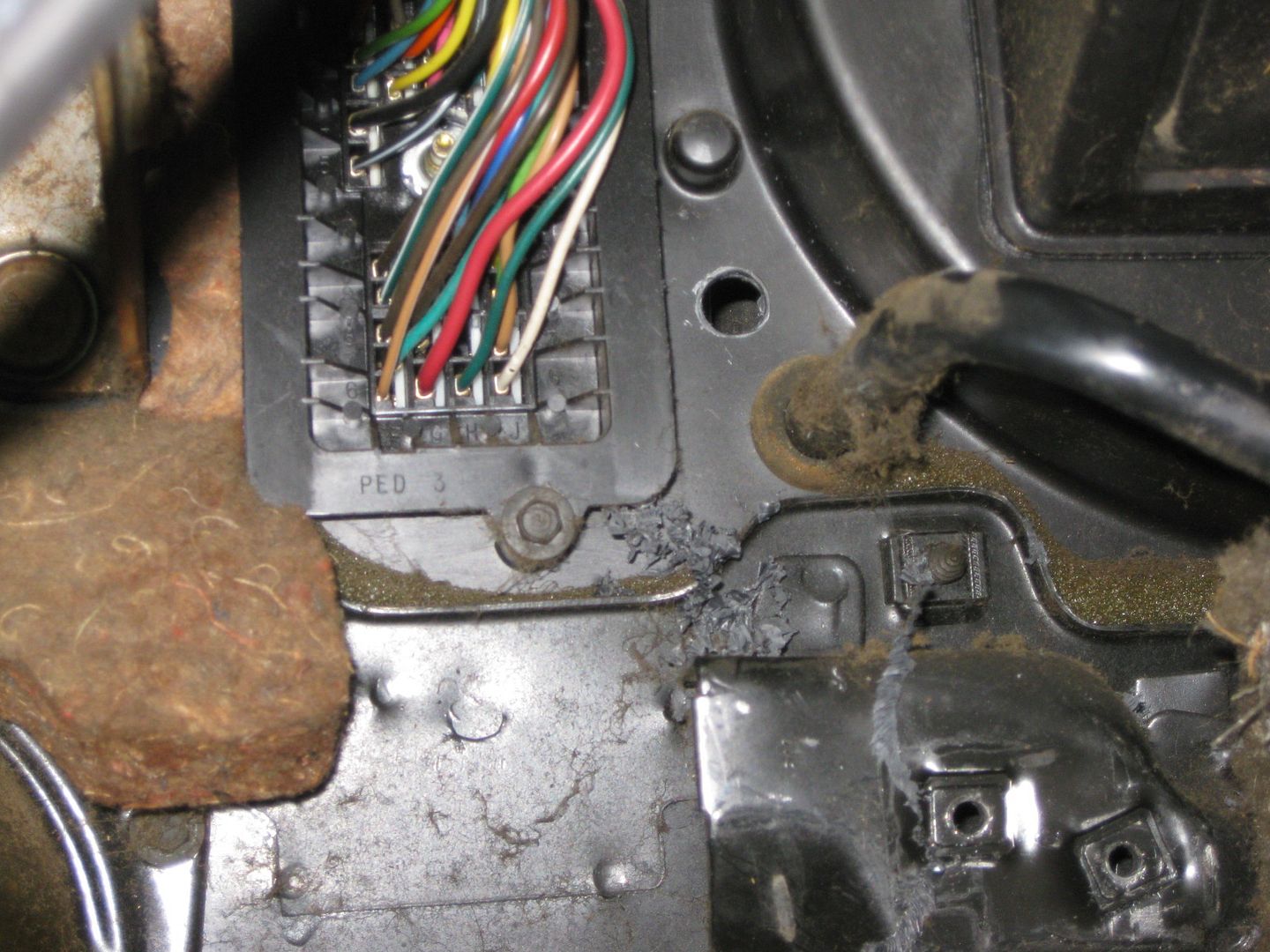

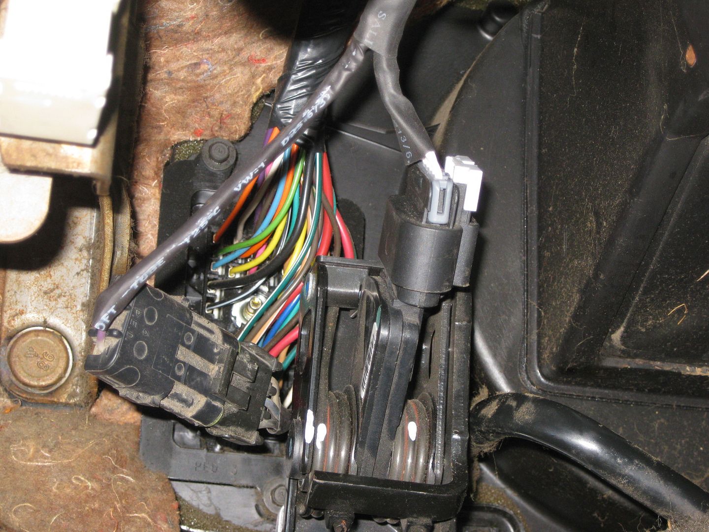
It is hard to see in this picture, but the harness comes through the firewall and goes under the C100 and under the brake booster to the other side:
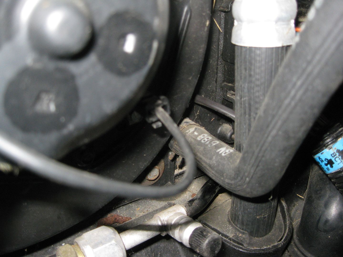
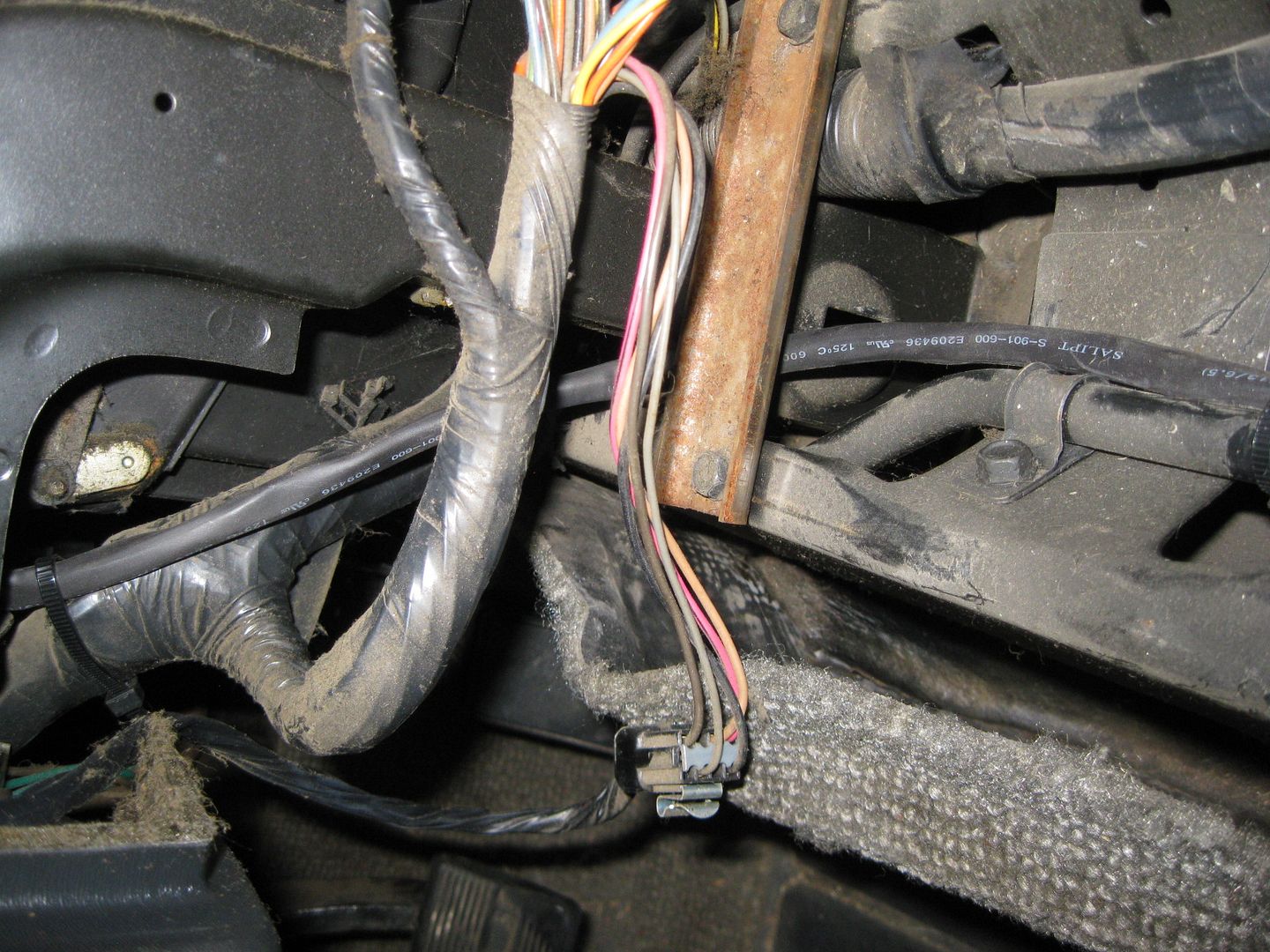
Plenty of excess wire for when the sensor is installed in the booster. The raised flat circular surface will be drilled for the new sensor:
Back inside, the pedals were installed again and the jumper harness connected and routed through the center console area:
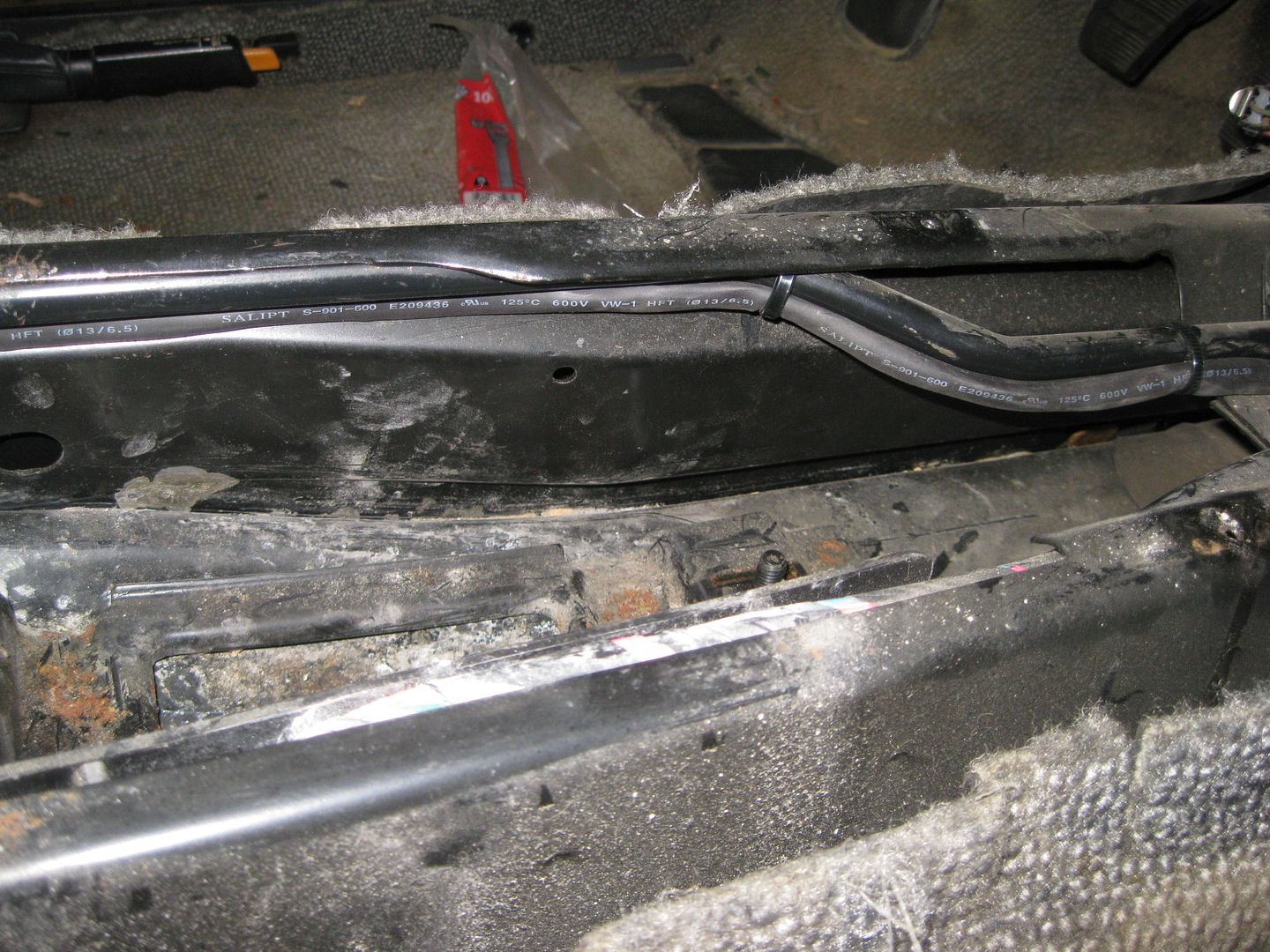

Also started working on the wiring for the TCM. All the needed resistors to mimic the solenoids and temp sensor as well as the 120 ohm terminator in the GMLAN line were all added in the body of the harness.
Still more wiring to be done...
|
|
|
|