
 
     |
| Northstar rebuild: Will style (Page 44/119) |

|
Will
|
MAY 02, 08:58 AM
|
|
All eight pistons are in. I stayed up all night Tuesday and got two in, then ran out of assembly lube, couldn't find the extra tube I'd bought ('cause I'd stayed up all night most likely) and had to go to work Wednesday.
Got back last night and got the rest in. Actually installing the pistons and rods is not that difficult... the cleaning and prep work that goes into getting there that's time consuming. I have a pile of ziploc bags two feet high from cleaning, measuring, marking, etc all the internal parts.
|
|
|
|
Will
|
MAY 05, 09:15 AM
|
|
| quote | Originally posted by Nashco:
I can't believe you're going through all of this and you're putting a bone stock top end back onto it. You really have lost it, I think the coal dust is getting to you.
|
|
Maybe I have lost it, but I want to drive the damn thing.
I want to do a hard break-in on the short block.
If I change the top end components, not only will I have to rewire for tunable engine management, I'll have to take the break-in run time to tune the new combo... which means that it won't get it's hard break-in.
There's a specific combo I'm moving toward, and I'd like to do the bolt on mods (headers, throttle per cylinder) first, just to see how far I can take stock heads/cams.
The porting and cam work on a Northstar is not very well developed, so I'll be moving very carefully in that area to get the best result.
|
|
|
|
Scoobysruvenge
|
MAY 05, 10:15 AM
|
|
Will,
Are you worried about losing low speed drivability going with 8 throttle plates or are you just looking for top end juice??????
|
|

|
motoracer838
|
MAY 05, 10:21 AM
|
|
| quote | Originally posted by Will:
All eight pistons are in. I stayed up all night Tuesday and got two in, then ran out of assembly lube, couldn't find the extra tube I'd bought ('cause I'd stayed up all night most likely) and had to go to work Wednesday.
Got back last night and got the rest in. Actually installing the pistons and rods is not that difficult... the cleaning and prep work that goes into getting there that's time consuming. I have a pile of ziploc bags two feet high from cleaning, measuring, marking, etc all the internal parts. |
|
Will, I know I've been bustin' on ya a little bit, just havin' a little fun, but we would love to see a few pics of this jewel of a lower end your assembling.
Keep up the good work. Joe
|
|
|
|
Will
|
MAY 05, 10:33 AM
|
|
| quote | Originally posted by Scoobysruvenge:
Will,
Are you worried about losing low speed drivability going with 8 throttle plates or are you just looking for top end juice?????? |
|
Actually, throttle per cylinder intakes REALLY civilize big cam engines. With one, I can go to 288, 292 or 310 cams and maintain decent low RPM torque and drivability, as well as idle quality. They are a complicated/expensive way to have your cake and eat it too.
The biggest headache is manifold pressure sensing and drawing vacuum for vacuum accessories.
I have pics.... I just haven't had time to resize, post and adequately describe things yet.[This message has been edited by Will (edited 05-05-2009).]
|
|
|
|
tjm4fun
|
MAY 05, 11:22 AM
|
|
| quote | Originally posted by Will:
Maybe I have lost it, but I want to drive the damn thing.
I want to do a hard break-in on the short block.
If I change the top end components, not only will I have to rewire for tunable engine management, I'll have to take the break-in run time to tune the new combo... which means that it won't get it's hard break-in.
|
|
Wow, now that caught me by surprise! I did not expect you to be the type of guy who would do a hard break in...
But I do agree with that method, I have always done hard break-ins, and have never been disappointed with the results.
Always felt, I put it together, I did all the proper checks, fits, etc, there is no reason to baby it out of the stall... besides if something is flawed that did not get caught in the machining, at least everything is all setup to pull it back out again..... ( only failure was one crank that they missed an internal crack, sheared a 3.8 steel turbo crank in half at the middle joint, never dealt with that shop again)
|
|
|
|
Will
|
MAY 05, 12:43 PM
|
|
Hard break-ins are great as long as you have enough oil filter flow capacity to remove the risk of pumping break-in debris into your bearings.
Most filters do not have enough flow capacity for the engine's max RPM oil flow and lift the bypass valve, thereby allowing unfiltered oil to circulate, and potentially break-in debris to flow into the bearings. With a filter that has enough capacity to flow the engine's full volume of oil without lifting the bypass, then the risk of pumping break-in debris to places it shouldn't go is eliminated.
The problem with doing this on a Northstar is that the engine has a HUGE oil flow (12+ gpm at high rpm) and there isn't much room for a bulky filter and large oil lines (oil ports in the block have the ID of fittings for -12 line) underneath the engine in the Fiero engine compartment.
|
|
|
|
Will
|
MAY 05, 10:45 PM
|
|
A separated view of each cylinder's worth of reciprocating components:
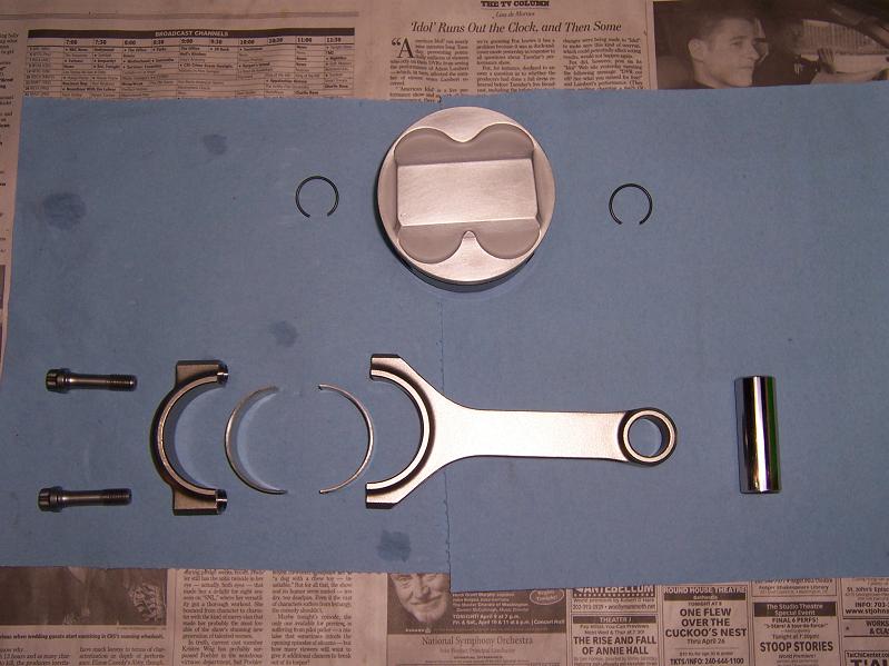
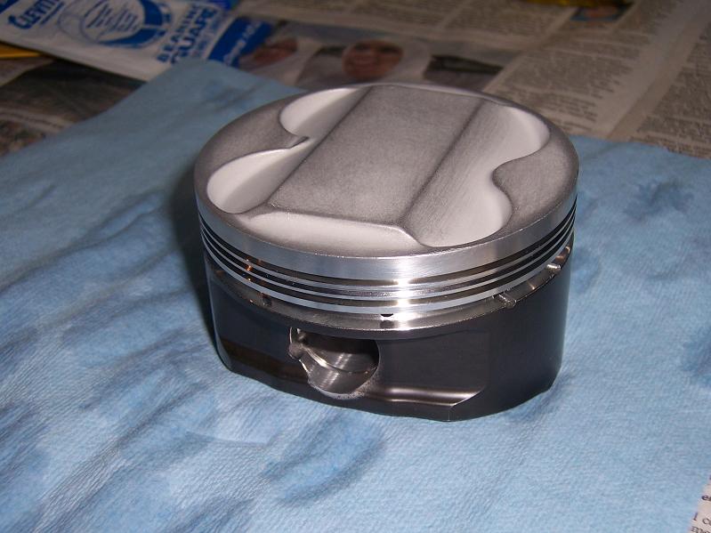
A domed piston. The intake side is on the left.
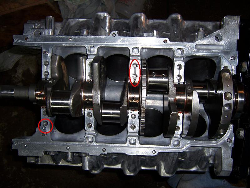
This is the crank sitting in the block. 1st main is on the left. At the bottom left note the channel between that small oil gallery and the one main bolt hole. At the top of main #3 (and all the other mains), note the channel connecting the two main bolt holes. You can also see the trigger wheel behind the #3 main.
This is the lower crank case, the bearings annointed with the blood of a virg--err... assembly lube.
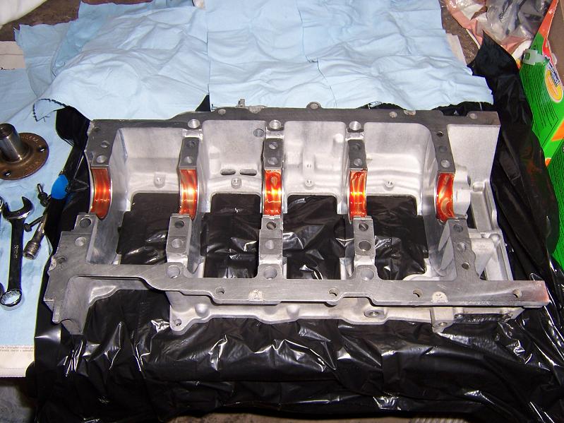
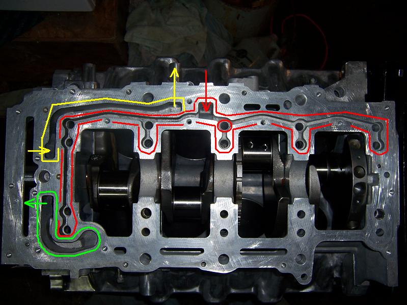
This is the Northstar's priority main oil system cast into the bottom of the lower crank case. The bottom end of this engine maintains absolute priority for lubrication. The top end is only lubed with "leftover" oil pressure that has already gone through the bottom end. Outlined in green is the oil pickup passage whereby oil is drawn from the sump into the pump. Yellow is pressurized oil from the pump to the oil filter adapter. Red is filtered oil from the filter to the main bearings. The oil travels from the bottom of the lower crank case through the annular space AROUND the main bolts, into the channels around the main bolt holes in the picture above, and thence into the bearings.
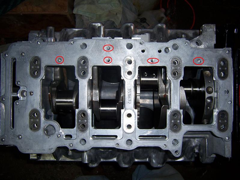
This is the oil manifold that caps off the oil channels. It has linear seals laid into it to keep the pressurized oil where it belongs. I found out something I like about the '93 block: the circled bolt holes are NOT present in the later ('95+) oil manifolds and lower crank cases. The '93's theoretically seal better, although GM wouldn't have removed those bolt holes if they were actually useful. They probably found that they didn't actually need them, but I like having them. The discolored areas around the main bolt holes are actually steel inserts cast into the aluminum plate. They serve as wear surfaces/washers for tightening down the main bolts on an otherwise aluminum surface.
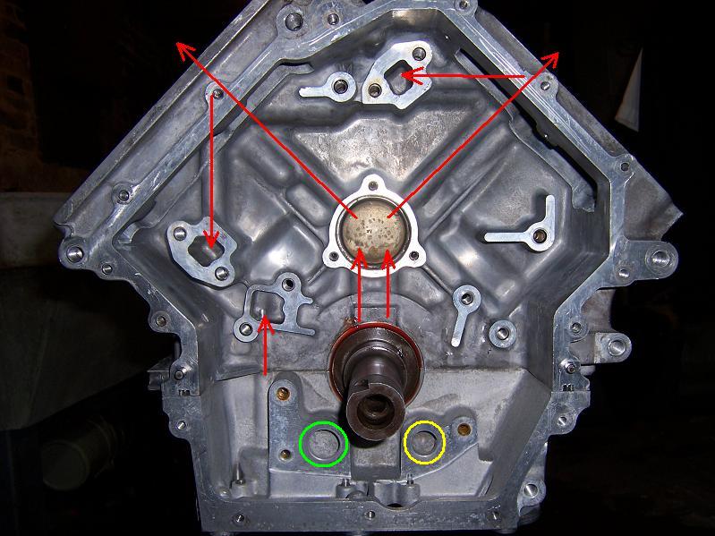
This is a diagram of the top-end oiling passages in the block. Oil that has gone through the forward main bearing goes up two galleries and into a small volume behind the timing drive intermediate sprocket. From there it goes up one more gallery to each cylinder head. There is a small channel cast into each deck surface whereby oil from the supply galleries goes into dead-end galleries to provide pressure for the secondary chain tensioners. The primary tensioner, surprisingly, has oil pressure priority equivalent to a main bearing and is pressurized by the small gallery in the lower left in the 4th picture up. The oil pickup is circled in green, the pressurized oil inlet in yellow. The pump is concentric on the crank snout and bolts on following the primary timing sprocket on the crank. The pump is driven by a sleeve that is simply clamped by the damper and is not positively driven from the crankshaft. This seems like a strange way to do things to me, but it works.
 [This message has been edited by Will (edited 05-05-2009).]
|
|
|
|
Erik
|
MAY 05, 11:16 PM
|
|
| quote | Originally posted by Will:
A separated view of each cylinder's worth of reciprocating components:
A domed piston. The intake side is on the left.
This is the crank sitting in the block. 1st main is on the left. At the bottom left note the channel between that small oil gallery and the one main bolt hole. At the top of main #3 (and all the other mains), note the channel connecting the two main bolt holes.
This is the lower crank case, the bearings annointed with the blood of a virg--err... assembly lube.
This is the Northstar's priority main oil system cast into the bottom of the lower crank case. The bottom end of this engine maintains absolute priority for lubrication. The top end is only lubed with "leftover" oil pressure that has already gone through the bottom end. Outlined in green is the oil pickup passage whereby oil is drawn from the sump into the pump. Yellow is pressurized oil from the pump to the oil filter adapter. Red is filtered oil from the filter to the main bearings. The oil travels from the bottom of the lower crank case through the annular space AROUND the main bolts, into the channels around the main bolt holes in the picture above, and thence into the bearings.
This is the oil manifold that caps off the oil channels. It has linear seals laid into it to keep the pressurized oil where it belongs. I found out something I like about the '93 block: the circled bolt holes are NOT present in the later ('95+) oil manifolds and lower crank cases. The '93's theoretically seal better, although GM wouldn't have removed those bolt holes if they were actually useful. They probably found that they didn't actually need them, but I like having them. The discolored areas around the main bolt holes are actually steel inserts cast into the aluminum plate. They serve as wear surfaces/washers for tightening down the main bolts on an otherwise aluminum surface.
This is a diagram of the top-end oiling passages in the block. Oil that has gone through the forward main bearing goes up two galleries and into a small volume behind the timing drive intermediate sprocket. From there it goes up one more gallery to each cylinder head. There is a small channel cast into each deck surface whereby oil from the supply galleries goes into dead-end galleries to provide pressure for the secondary chain tensioners. The primary tensioner, surprisingly, has oil pressure priority equivalent to a main bearing and is pressurized by the small gallery in the lower left in the 4th picture up. The oil pickup is circled in green, the pressurized oil inlet in yellow. The pump is concentric on the crank snout and bolts on following the primary timing sprocket on the crank. The pump is driven by a sleeve that is simply clamped by the damper and is not positively driven from the crankshaft. This seems like a strange way to do things to me, but it works.
|
|
cool..what pistons are those??
|
|
|
|
Will
|
MAY 05, 11:21 PM
|
|
|
Custom cut, based on a standard CP forging. Coatings by Calico. I didn't snap any pics of the rings... but as far as the camera can tell, they're just rings. Only my bill and my micrometer say they're special.
|
|
|
|