
 
     |
| Blooze Own: An F355 Six Speed N* Build Thread (Page 40/126) |

|
aaronkoch
|
APR 06, 12:52 PM
|
|
|
Considering the added length of the arm, 325 lbs will probably be fine..
|
|
|
|
Bloozberry
|
APR 10, 08:37 PM
|
|
Thanks for the tip ccfiero… drain holes are now on the list of things to do! Thanks too for your input Aaron. I want the car to ride low, but our secondary roads here in Nova Scotia are pretty pathetic. I think 325 will be a good compromise between being too stiff and bottoming out especially given the added leverage of the longer arms.
Now, on to more pictures. Once I had the springs built up, I tried them on but without any weight on the cross-member the lower control arms were being forced all the way down. Since I’m only mocking things up at this time, I removed the springs and installed just the shocks for now. It’s pretty straightforward, a bolt through the lower control arm mounts and the hemispherical joint at the bottom of the shock, then feed the top of the shock up through the hole in the upper spring pocket on the cross-member. There’s a pair of poly bushings on the top of the shock shaft similar to the ones on the sway bar end links:

I wanted to add this next photo for two reasons. The first is that it shows the stock spring seat in the upper part of the cross-member. With these new springs that are shorter and smaller in diameter than the stock ones, there’s a heavy duty collar that comes with the HT Motorsports parts that adapts the new spring to the OEM upper spring seat. I’ll add a picture of it later since I don’t have one ready right now.
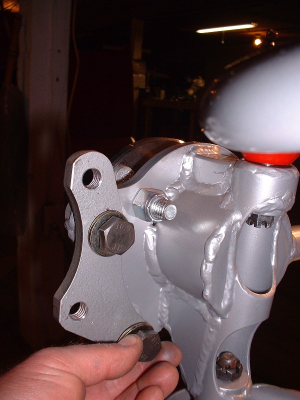
The second reason was to point out the yellow spacers I had to fabricate from steel tubing to center the bottom of the shock on the lower mounting bolt. The space between the mounting ears welded to the lower control arm is way too wide for the width of the heim-joint at the bottom of the shock. It’s a simple fix, but one that I feel should have been included in the kit from HT.

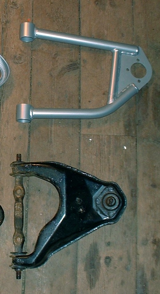
With the shock installed, the next step is adding the upper control arm. Here is a picture of the OEM and 3” longer one for comparison’s sake:
Installing the upper control arm is a breeze, just two bolts through the upper pivot bolt. Getting to that point is a little harder though. HT doesn't provide the upper control arm pivot bolt so you have to re-use your stock one, and that can be a PITA to take off. To remove it from the stock arm, you have to dig/burn/press out the stock rubber bushings from both sides of the control arm before the pivot bolt can be slid out. The usual problems of bushing sleeves seized to the pivot bolt turn what should be a simple ten minute procedure into an hour long drama complete with swearing, flying tools, and either burnt, cut, or pinched skin.

The front-end caster and camber alignment depends on where you tighten the two bolts through the elongated holes in the top of the cross-member though. The nuts that the bolts thread into aren’t captured to the underside of the spring seat unfortunately. Instead they’re welded together onto a thin piece of sheet metal that’s got to be held in place while tightening the bolts. That generally goes OK, but the metal is notorious for twisting out of shape if you ever decide to loosen the bolts.

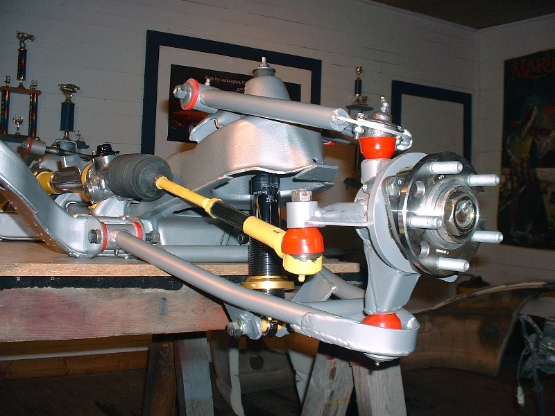
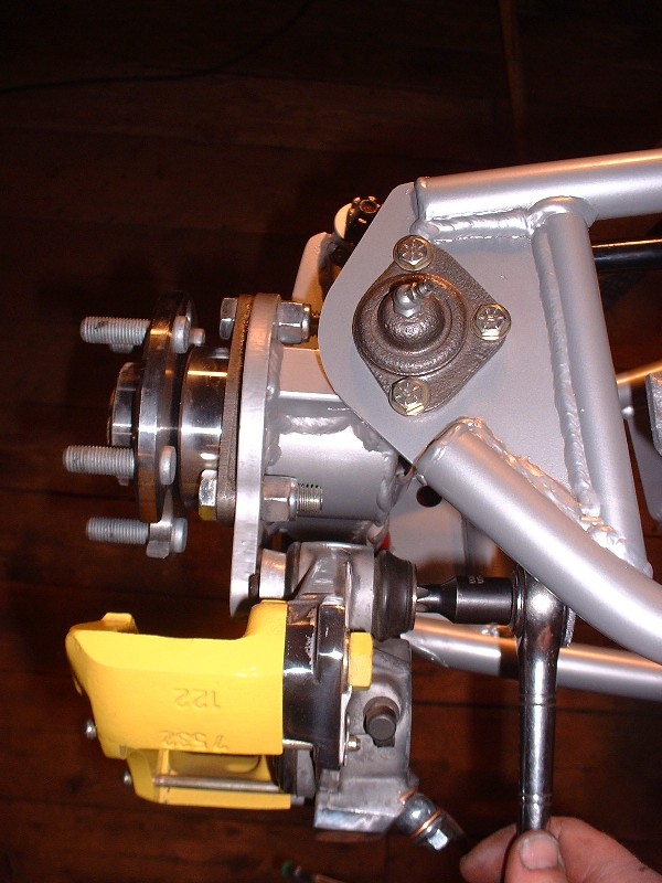
The next piece of the puzzle is the knuckle assembly. It’s only held onto the spindly little control arms by the upper and lower ball joints and the outer tie rod. In this view you can clearly see the front to rear tilt of the upper control arm. This property of the arm is what determines the amount of anti-dive.
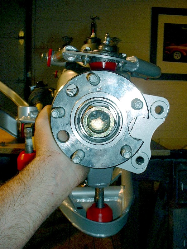
HT designed a generous amount of accessibility to the upper and lower ball joint nuts through large windows cut out of the backside of the tubular uprights:
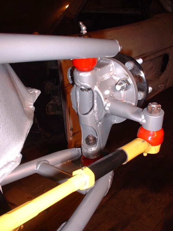
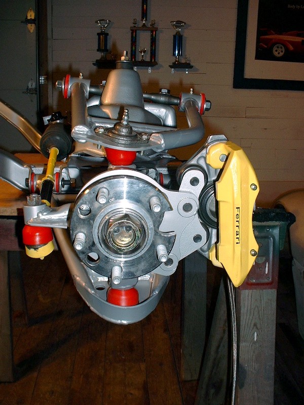
And here’s the street-side view of the installed knuckle assembly. On the one hand, the whole thing just seems impossibly weak to do the job it does, but on the other,
it looks decidedly race-like… low weight, small visual mass, and a hanging-way-out-there look. Heavy-weight brakes will more than compensate for all that low weight stuff soon enough though.
|
|

|
fierogt28
|
APR 10, 08:57 PM
|
|
Nice job Blooze, very impressive... ------------------
fierogt28
88 GT, Loaded, 5-speed.
88 GT, 5-speed. All original.
|
|
|
|
Fierobsessed
|
APR 10, 11:01 PM
|
|
|
Curious, do the Corvette rotors clear the Lower control arm? It's a known problem on stock 88 cars in the front.
|
|

|
RWDPLZ
|
APR 14, 09:55 PM
|
|
The thread was already awesome, and then, the drawings! You are NUTS!
My senior project in high school CAD class was a Fiero, nowhere near the level of detail and accuracy of your drawings.

|
|
|
|
Bloozberry
|
APR 23, 09:06 PM
|
|
Thanks fierogt28 and RWDPLZ (although I'm not so sure calling me nuts was a compliment  ) For Fierobsessed, I've checked my lower control arms for interference with the brake rotors and indeed they contact each other, although the condition may only exist at the extreme end of the suspension travel in rebound. I'll have to look more closely at this and post some findings the next time. ) For Fierobsessed, I've checked my lower control arms for interference with the brake rotors and indeed they contact each other, although the condition may only exist at the extreme end of the suspension travel in rebound. I'll have to look more closely at this and post some findings the next time.
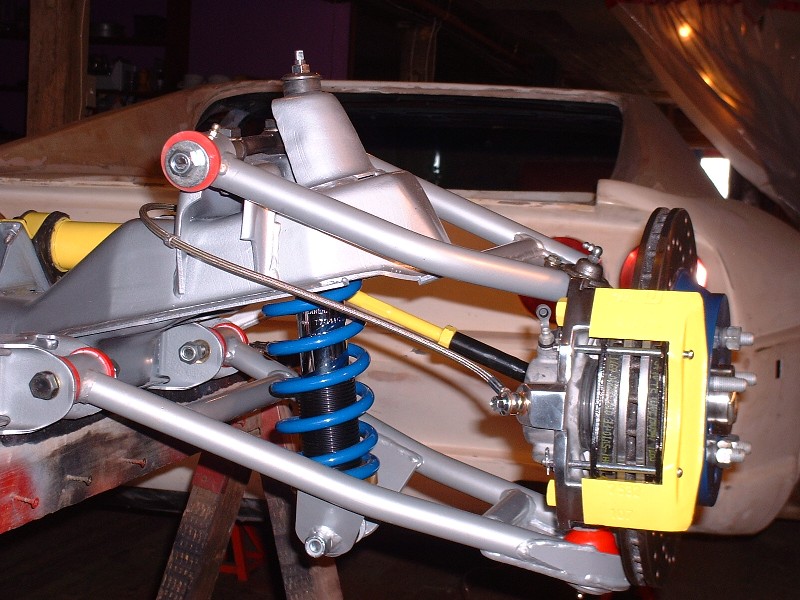
For this post, I'm going to finish up the assembly of the front crossmember with the addition of the brakes. As with the rear suspension, I opted for the 12" C4 Corvette rotors and stock '88 Fiero calipers. That meant simply bolting on the Fiero Addictions brake caliper adapter onto the HT knuckle...
... and then bolting the caliper onto the adapter using the stock caliper bolts through the sliders. As with the rear, I discovered that the rotors can be installed and removed from the hub flange with the caliper installed.
Here's the street-side view of installed caliper... I'll go along with this set-up for now and maybe someday I'll beg the Reprovisioning-Fairy for the four piston caliper upgrade. 
With the caliper installed, it was a simple matter of slipping on the rotors at a bit of an angle, sticking on a couple lug nuts to hold them square to the hub, and installing the brake pads in the same manner as the rears were done earlier.
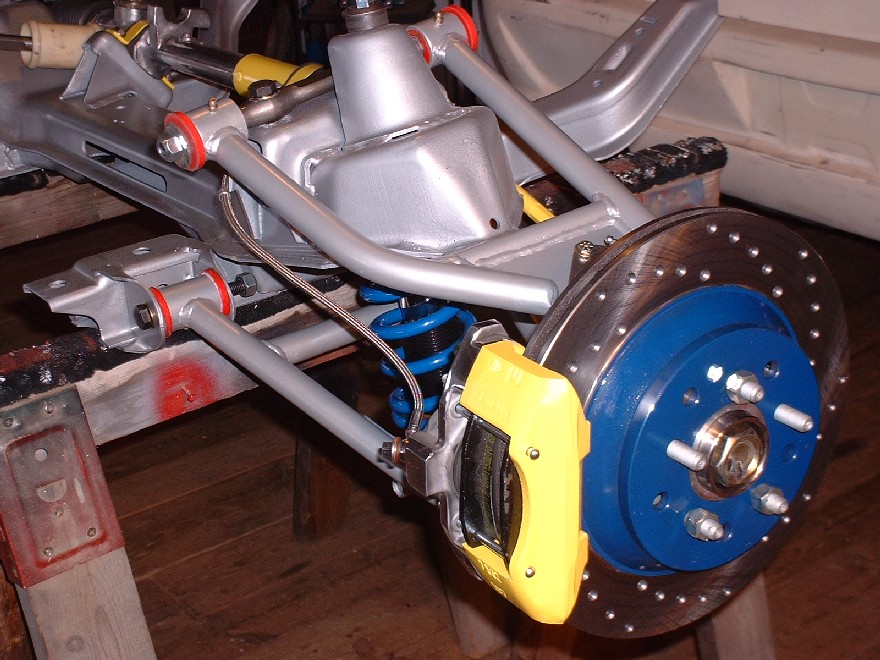
I used stainless braided flex lines to complete the look and for the improved pedal feel. The old rubber lines were too short anyways. Here I've installed the springs to complete the mock-up for the picture, but they force the control arms downward to the max rebound position and make it harder to install the crossmember as a unit back into the car. I'll be taking them off to install the front end later.
And finally, here's an inboard shot to complete all the possible angles anyone could possibly want to see. It's kind of colorful, but in my defence I didn't get to choose the color of the ball joint boots or bushings. I would've gone for lime green 
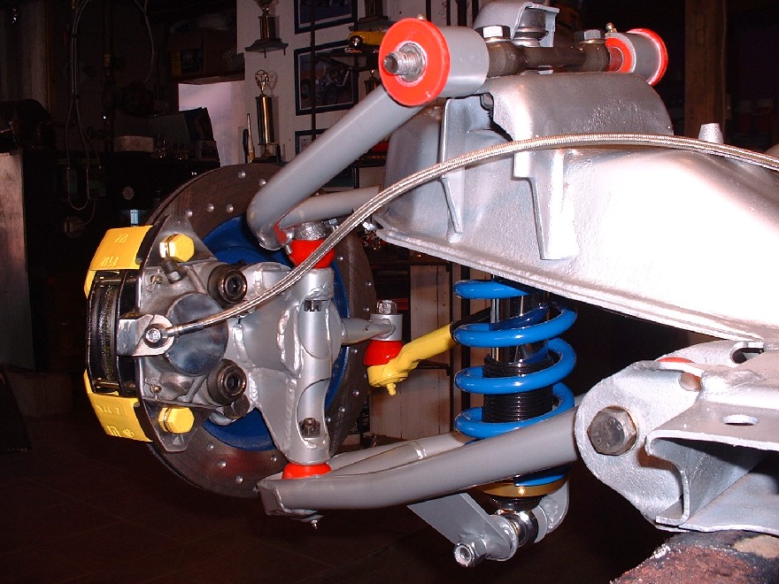
|
|
|
|
doublec4
|
APR 24, 12:13 AM
|
|
|
Looks great as usual! Such a high level of detail into this. I had no doubt it would turn out like that!
|
|
|
|
88GTS
|
APR 24, 10:41 AM
|
|
Blooz, your new springs have a smaller diameter than stock - how do they seat at the top?
| quote | Originally posted by Bloozberry:
And finally, here's an inboard shot to complete all the possible angles anyone could possibly want to see. It's kind of colorful, but in my defence I didn't get to choose the color of the ball joint boots or bushings. I would've gone for lime green
|
|
|
|
|
|
Tinkrr
|
APR 24, 10:55 AM
|
|
I've never seen the dust boots in lime green but they do come in yellow and you seem to have used that a lot. Checkout my left rear inner tie rod.

|
|
|
|
Bloozberry
|
APR 25, 08:49 PM
|
|
| quote | Originally posted by 88GTS:
Blooz, your new springs have a smaller diameter than stock - how do they seat at the top?
|
|
Thanks for pointing that out 88GTS... here's the answer:
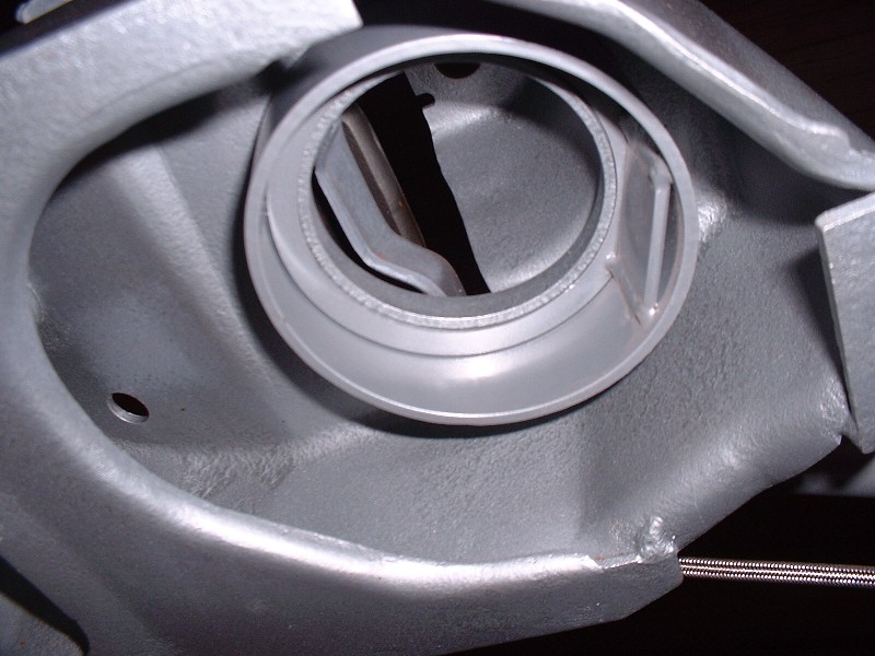
When you order the '88 front coilovers from HT Motorsports, they send along a spring adapter that looks like this. The top-side has a ring welded onto it that makes the ID a bit smaller than the bottom side (ignore the flat tab welded on the ID):
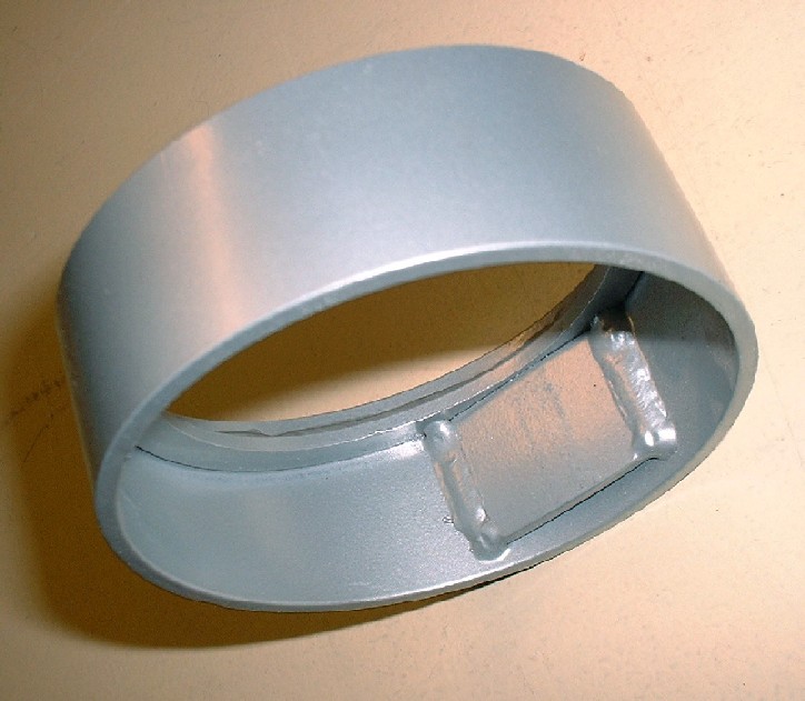
The end of the adapter with the smaller ID fits tightly on the OEM spring collar in the crossmember. The adapter is also wedge-shaped so once you've slipped it up through the spring pocket you also have to orient it so the thinner edge of the adapter is towards the inboard-side of the car. That flat tab welded on the ID is on the wider edge of the adapter, so it's got to go towards the road-side.
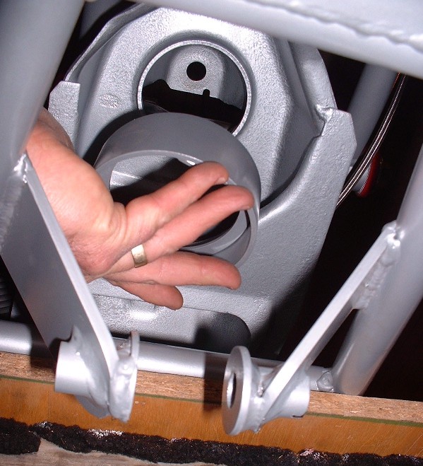
In the picture below, the HT spring seat isn't perfectly lined up, but you get the picture. Once it's up there, you peen the OEM spring seat collar over to lock the HT adapter to the crossmember. HT also recommends adding a thick bead of silicone between the top surface of their adapter and the crossmember to make any movement between the two pieces as squeakless (is that a word?) as possible. HT does say that peening isn't absolutely necessary since the spring is always in enough compression to hold the adapter in place. I think I'll weld it into place on mine.
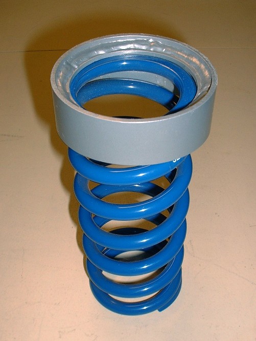
I don't have a picture of the springs installed from the bottom side of the crossmember, but here's how the spring seats inside the adpater.
|
|
|
|