
 
     |
| Blooze Own: An F355 Six Speed N* Build Thread (Page 39/126) |

|
Bloozberry
|
MAR 24, 02:55 PM
|
|
| quote | Originally posted by ccfiero350:
We have discrepancy in dims. |
|
Yep... for two reasons... the first is that I thought you meant the distance on the diagonal, ie from the outboard axis of the lateral links where they are attached to the knuckle, up to the strut bushing; and second: I accidentally used the wrong scaling factor 20:1 instead of 10:1 when I gave you the 50.2" figure.
So, now that I know you want the distance in "up" plane (the green plane in your last rendering), the 50.2" number should be 595 mm (23.4").
Great 3D drawing by the way. Because there's the potential for miscommunication between us and therefore numerous trial and error drawings, if you don't mind, I'd like to sort out any other iterations of the suspension movements in PM's rather than directly in the thread there ccfiero. That way we won't post misleading or incorrect info. I really do appreciate the work you've done but I'd like to keep the actual build thread as clean as possible.
|
|

|
ccfiero350
|
MAR 24, 03:48 PM
|
|
Now we are the same page! That number is is more like it.
No problem on the clean thread, but rather use email if we could. I'll send you a 3D pdf you can measure from to the last address you sent me.
------------------
yellow 88 GT, not stock
white 88 notchie, 4 banger
|
|
|
|
Bloozberry
|
MAR 27, 09:52 PM
|
|
For those of you who found the 3D animations as entertaining as I did, CCFiero's sent me some more of them with the 3" longer control arms for me to look at before he posts them, but I haven't had a chance yet.  As cool as they are, I'll still have to go through my own exercise to determine the best possible location of the lateral links height-wise, and cross car width-wise, plus whether I should increase the angle on the trailing links to improve anti-squat, and raise the upper strut mounts to get more travel. As cool as they are, I'll still have to go through my own exercise to determine the best possible location of the lateral links height-wise, and cross car width-wise, plus whether I should increase the angle on the trailing links to improve anti-squat, and raise the upper strut mounts to get more travel.
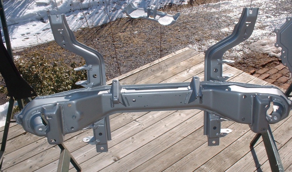
For now, it's back to the front suspension make-over. It’s amazing how a good sandblaster can take a painstaking, backbreaking, four-hour crappy task with a wire wheel on an angle grinder, and turn it into a joy to do. It took me less than half an hour and two $10 bags of crushed glass to strip the old paint and rust out of every pore, nook, and cranny of the front cross member. My compressor just can't handle the bigger jobs, so a friend of mine who owns a top-notch paint shop lets me do the big parts out-back at his shop where he’s got the right set up. Once stripped, I don’t like leaving parts sitting around too long so the shop primed it with an epoxy primer just as soon as it was done. A couple hours later it was home and painted in the final color.
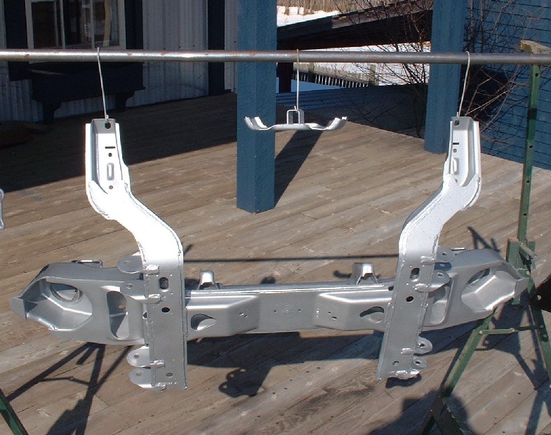
I chose silver because I wanted a different color than the bottom of the car (which will be black), and a light color makes it look less heavy and massive. I know, I know, few people will ever see the bottom of the car, but I want those who do to see right away that this was a ground-up restoration. I find that if everything gets painted black, after a year or two it takes a close look to tell whether it was redone or not. I’d rather it stand out if someone actually takes the time to look under the car.
While I was doing this, a big package arrived in the mail. All the front end parts I ordered from HT were delivered, all nicely packaged up in bubble wrap and foam peanuts (I hate peanuts). Look at all these purdy pieces:
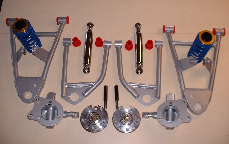
I’ll hone in on each piece separately to give you a better look, and to stretch out the few remaining photos I have before I’ll have to get back to actually working on the car.  The most intricate pieces are the drop spindles. There’s a lot of work that went in to these pieces so I can understand the premium price tag better now. The most intricate pieces are the drop spindles. There’s a lot of work that went in to these pieces so I can understand the premium price tag better now.

They’ve been ingeniously designed to do away with the OEM ’88 Fiero-specific front bearing assemblies and made to accept the far more common and inexpensive Fiero rear bearing assemblies.
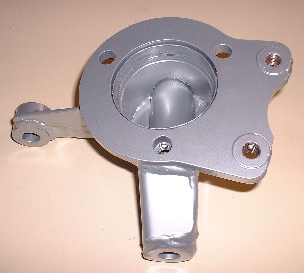
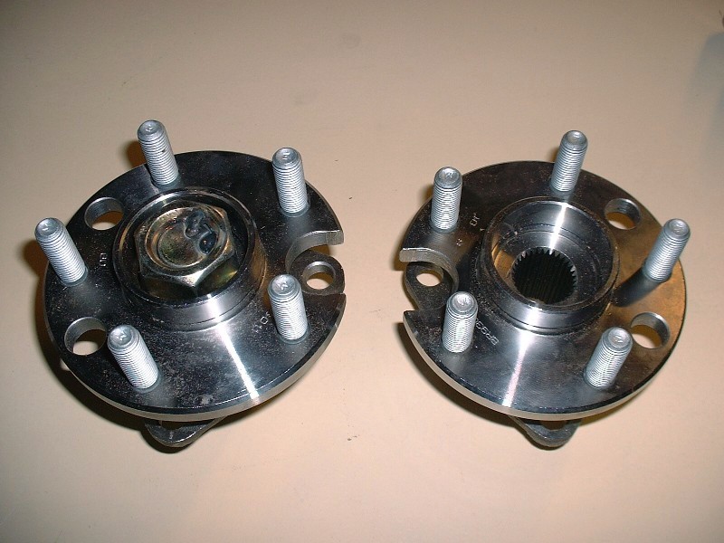
Because the rear bearing assemblies were originally designed for an axle and axle nut to hold the bearing halves together, these bearings are modified with a large bolt as a substitute for the axle. On the left is the modified bearing and on the right, a stock bearing assembly. Note that the large nut has been spot welded to keep it from ever backing off.
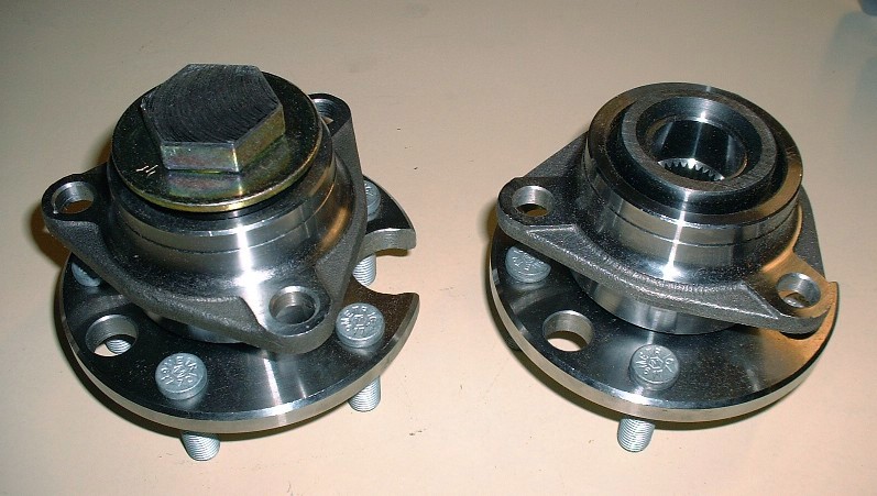
Here’s the rear view of the same pair as above. To solve clearance issues with the inside depth of the drop spindle, the head of the large bolt was machined down somewhat.
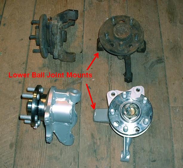
Finally, here’s what the spindle and bearings look like when assembled as compared to the OEM parts. The 1.5” drop is clearly obvious when you compare the two left-most knuckles in the photo. Notice how much more of the lower ball joint mount extends beyond the diameter of the wheel flange on the new knuckle as compared to the OEM one. (Well, actually, the ball joint mount is in the same location, it’s the spindle that’s been raised making the mount look longer.) That should take care of some of that ugly gap between the top of the tires and the wheel well lip.
|
|
|
|
doublec4
|
MAR 27, 09:58 PM
|
|
Those look like some nice pieces! Its a great feeling getting parts in the mail 
Still watching this build
|
|
|
|
Reallybig
|
MAR 28, 01:55 AM
|
|
|
|
|
RCR
|
MAR 28, 07:56 PM
|
|
Looks great Blooze...I'm probably going silver on my front conversion, too, although I may play with some translucent powders.
Bob[This message has been edited by RCR (edited 03-28-2011).]
|
|
|
|
Fiero2m8
|
MAR 31, 12:56 AM
|
|
| quote | Originally posted by Bloozberry:
I chose silver because I wanted a different color than the bottom of the car (which will be black), and a light color makes it look less heavy and massive. I know, I know, few people will ever see the bottom of the car, but I want those who do to see right away that this was a ground-up restoration. I find that if everything gets painted black, after a year or two it takes a close look to tell whether it was redone or not. I’d rather it stand out if someone actually takes the time to look under the car.
|
|
| quote | Originally posted by RCR:
Looks great Blooze...I'm probably going silver on my front conversion, too, although I may play with some translucent powders.
Bob
|
|
Some similar tastes here , I wanted a contrast to the black frame too.
Fiero2m8
|
|
|
|
cptsnoopy
|
MAR 31, 01:52 AM
|
|
Lol Blooze, watching your thread is seriously threatening my wallet!
Charlie
|
|
|
|
Bloozberry
|
APR 05, 10:35 PM
|
|
Wow… time flies when you’re busy! I see that my thread is getting closer to the bottom of the first page so I guess it’s time for another update. Thanks guys for your comments. I'm a huge Doors fan Reallybig but I had never seen Wierd Al's take on anything from them. If you see an eBay ad for styrofoam peanuts anytime soon, you can rest assured they're from me! As for Fiero2M8, I've been keeping a close eye on your amazing build too. I feel like my suspension is the Chevette equivalent to your Cadillac version though, so I try not to look too often otherwise I'll either get discouraged, or end up like Cptsnoopy and risk having even more money disappear from my thinning wallet.
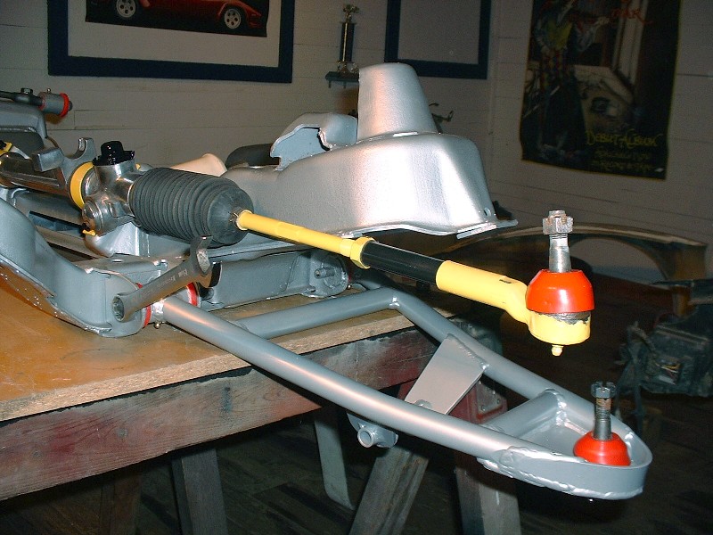
Continuing on with the front suspension build-up, the first thing I decided to attach back on the front crossmember was the tidied up steering rack. I checked it over for worn inner tie rods and the rack bushing, but the clearances seemed pretty much like new. So I blasted everything with crushed glass, polished a few highlights on the rack tube, and primed and painted the steel parts. Once it was ready, four simple bolts torqued to 20 lbft hold it to the crossmember:

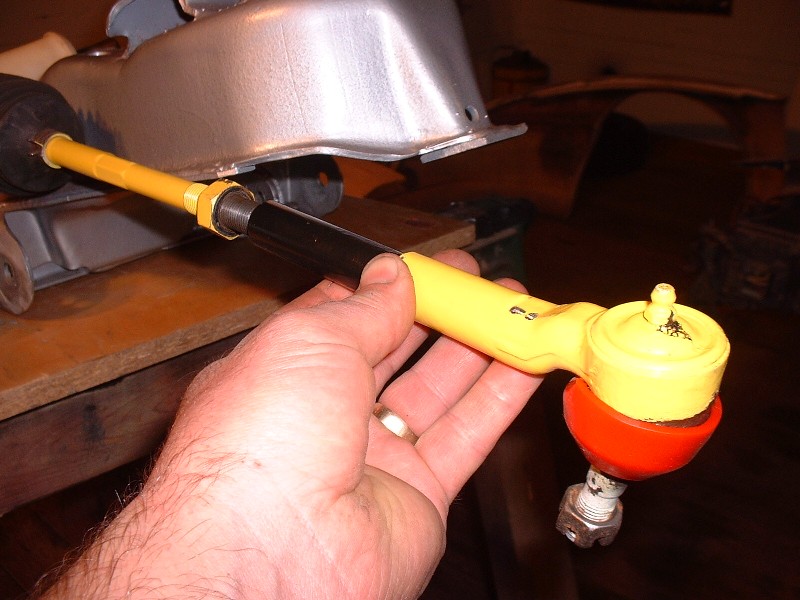
I think the guys that put in power assisted racks are amazing. It would be cool to do that too, but not on this first go around. I am on some sort of budget. Now those of you thinking ahead might be asking yourselves “How the heck is he going to connect those stock length outer tie rods up to his 3” extended control arms?”
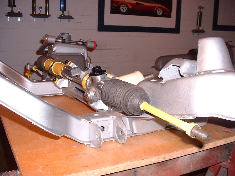
The answer to that is quite simple actually. A 3” tie rod extension tube with male threads on one end and female on the other is all that’s needed. This method keeps the inner and outer tie rod pivot points in the same spatial orientation relative to the upper and lower control arm pivots on the inboard side of things, and the upper and lower ball joints on the outboard side. I just hope that when I go to get this thing inspected (mandatory provincial inspection every two years) that they don’t raise their eyebrows too high when they see this. Maybe I should paint them yellow to blend in a little more. 
So next up is installing the lower control arms. Here’s what the old and the new look like side by each. The tubular arms look soooo much cleaner than the stamped steel ones. I just hope they’re as rigid or even more so than the OEM ones.
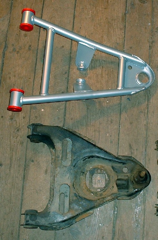
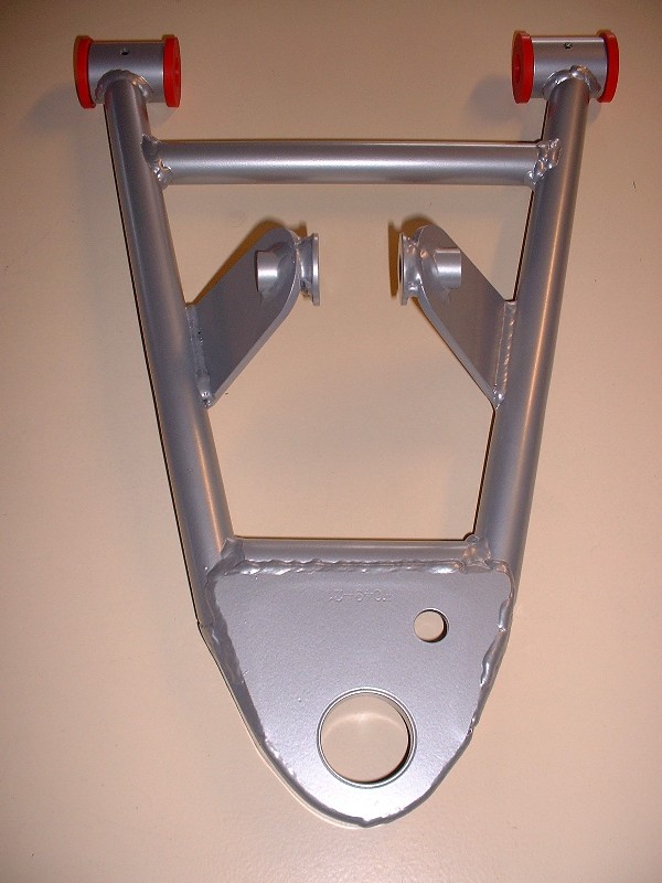
Notice how the lower shock mount ears extend quite significantly below the arm. This reduces ground clearance somewhat over uneven roads compared to the OEM ones but allows the use of the adjustable shocks. Aren’t they purrrrdy?
Getting these lower arms in the crossmember pockets with the urethane bushings takes a little poly grease and elbow grease. They certainly are a tight fit, which I suppose is better than having them flop around. The two nuts on the pivot bolts get torqued to 37 lbft + 270 degrees. (I’m only mocking things up at this point so I’m leaving things loose for now.)
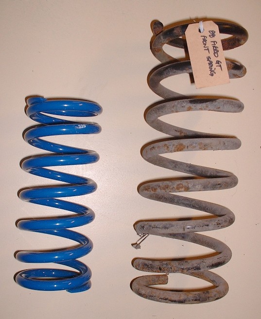
Next up is the installation of the shocks and springs. Here’s a close up of the my new 325 lb/in front springs vs the old OEM springs. I hope I didn’t make a mistake and order them too stiff. Only time will tell.
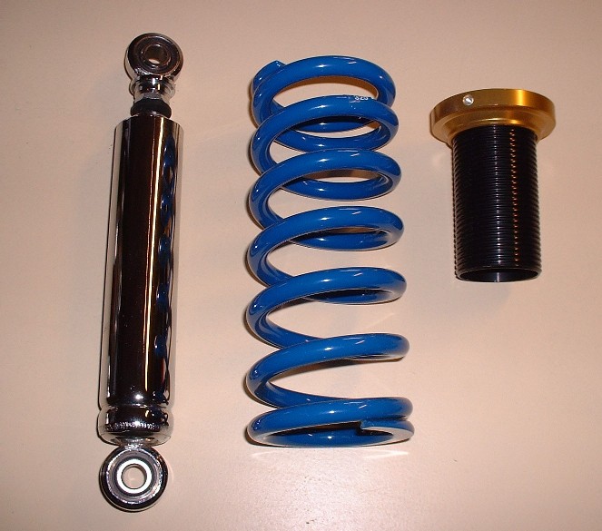
Here are the rest of the pieces that make up the coil-over shock. I got the Carerra chromed shocks with my suspension kit, not that anyone will see much of them once they get the adjustable tubes installed. The only thing missing from this photo is the upper spring seat. The springs are considerably smaller in diameter than the stock springs so HT Motorsports provide a heavy duty collar that serves as the new spring seat. I'll post a picture of them later.
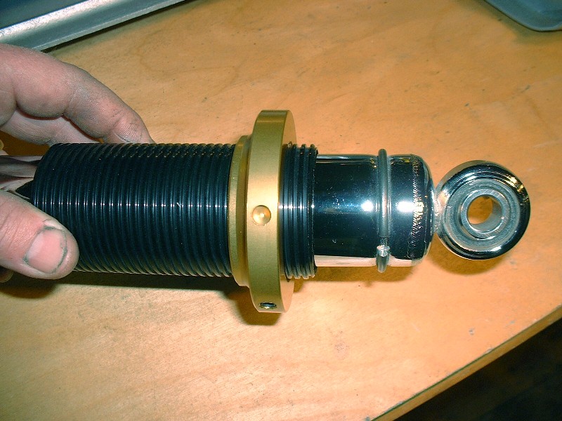
In order to keep the threaded adjuster tube from sliding off the end of the shock body, a powerful circ-clip is installed in the lower groove of the shock. Installing those clips nearly had me pitching the whole thing into the pond. It had to be one of the most frustrating aspects of this build so far… no kidding. I bent two pairs of circ-clip pliers, searched half a dozen times for the clips on the floor after they went flying every direction imaginable, pinched my finger tips, you name it… it happened.
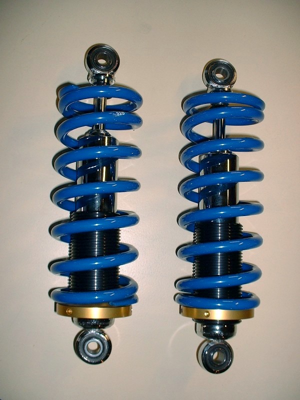
Once they were finally on, I could finish building up the coil-overs… which was just a matter of slipping the threaded tubes on and then the springs. This was one of those jobs you'd schedule 5 minutes to do and spend one hour. See what I meant by how little the chrome body of the shock shows? At least I’ll know they’re there.
|
|
|
|
ccfiero350
|
APR 06, 12:52 AM
|
|
Great build!
I added a couple of 3/16" weep holes to my tube arms. That pocket that holds the lower ball joint will fill with water and it needs a way to drain.
------------------
yellow 88 GT, not stock
white 88 notchie, 4 banger
|
|
|
|