Blooze Own: An F355 Six Speed N* Build Thread (Page 37/126)
RCR
MAR 10, 07:35 PM
Blooze...What can I say...Awesome stuff...I have the Herb Adams book and I know what you mean...Not the greatest. A book I would recomend if you can get your hands on it is "Race Car Vehicle Dynamics" by Milliken and Milliken. It's an SAE book. Bill and Doug Milliken invented the science of vehicle dynamics while researching the Corvair issues for GM, then taking the research a step further to dominate CAN AM racing. The history makes it a great read.
Bob
Lonster
MAR 13, 09:40 AM
What are the differences in geometry when changing the lower ball joints (1/2" or 1" drop) on the front suspension when compared to stock? Thought I would ask...
[This message has been edited by Lonster (edited 03-13-2011).]
aeffertz
MAR 17, 03:47 PM
Must be working on something big! Been a few days since an update.
EDIT:
Say, I'm about to tear into one of my alternators and starters to perform a rebuild like you documented in this thread. (Never would've thought about attempting it before I saw your posts!) I was just wondering if you used a special paint for the parts you painted on them?
Thanks and keep up the good work!
[This message has been edited by aeffertz (edited 03-17-2011).]
Bloozberry
MAR 17, 04:02 PM
Ha! Well you're right about it being something big... it's just not car related Been up to my eyeballs (and nose hairs) in stripping the 200 year old plaster and lat walls from the last room in our house that needed renovation. I'll be back on the project car soon though. (oops my wife just reminded me I'm spending quality time with her while we renovate together... I suppose that's not so bad.)
Bloozberry
MAR 18, 08:36 PM
Thanks for the reference to the Miliken & Miliken books there ccfiero and RCR. I’ll be ordering it.
As for Lonster, those lowering ball joints on the front-end are going to change the camber curve since the lower, longer arm remains parallel to the ground, but the upper, shorter control arm will ride with a more upward angle at the ball joint end, effectively making it shorter, and pulling the upper end of the knuckle inboard slightly. You’d probably have to counter this increase in static camber by slotting the upper ball joints to move the top of the knuckle outboard again. That would solve the “at-rest” issue, but dynamically you would also get a faster rate of camber change as you compressed the suspension than would otherwise be the case with normal ball joints. That would happen because the upper arm is already part way up it’s arc of movement. At least the camber will change in the correct direction so that’s not bad, but I can’t say if it would perform better or worse than stock. There would be increased bending stresses on the lower control arm where the ball joint is pressed into it. That’s an area that should be monitored for cracks occasionally if you go with the tall joints.
Well, I’m stuck in the middle of some home renos and immediately after that, I’ve got to change a clutch in a customer’s ’88 GT, and do some suspension work on the father-in-law’s MGB. That means I’ve got precious little time to devote to this thread at the moment. So, in the interests of keeping this thread from falling off the front page, I’ve decided to go a little out of sequence and mix things up a bit.
As super-interesting as suspension drawings can be I’m going to buy some time, go out on a limb, and post some front suspension pictures hoping you guys can keep what’s-what straight in your heads. This should buy me enough time to eek in a moment here and there between jobs to work on the 6” increased track-width drawings for the new rear and maybe get on with the cradle fabrication. So without further ado…
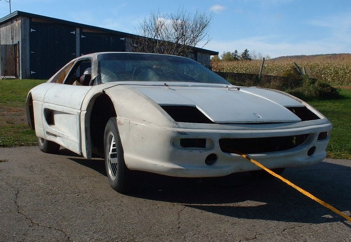
For those of you who’ve ever considered buying some of HT Motorsports stuff, these next couple posts are for you. I did a fair bit of research before I bought the increased track-width suspensions fore and aft, and so far, I can tell you I’m not disappointed. I knew that wheel spacers on the front just weren’t going to be in the cards because of the effects they have on everything from increasing scrub radius, to bending stresses on the bearings. Spacers that are up to an inch thick probably don’t change much, but here’s what I had to contend with…
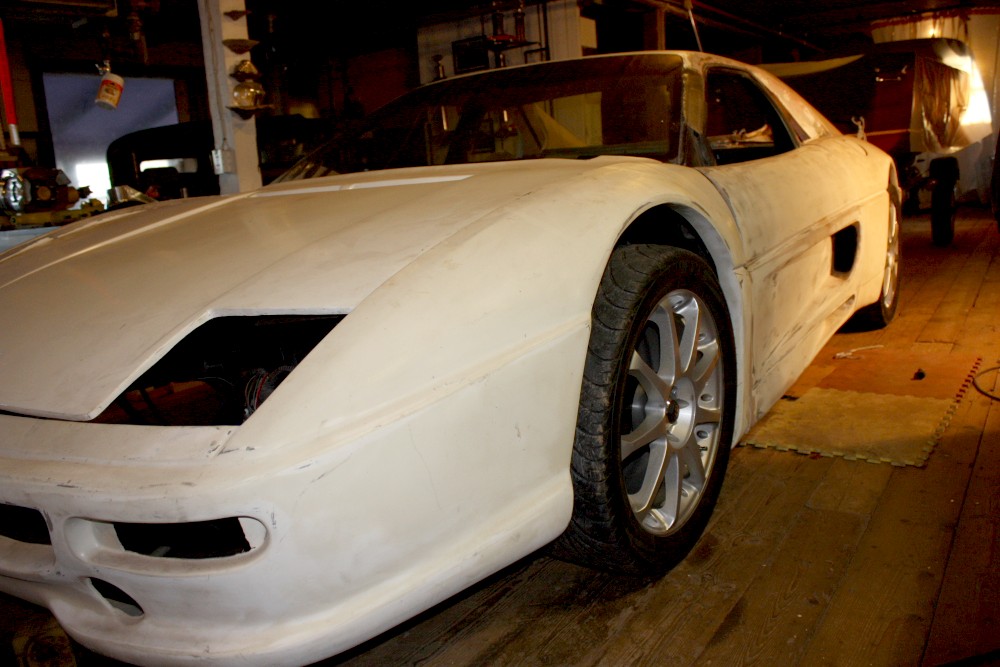
There just wasn’t any way that I was putting 3” spacers on the front. So I removed the wheels and blocked up the car with the lower control arms level to the ground. Then, I placed several different wheels with known widths and offsets in the fender well where I wanted the wheel to sit, and carefully measured the gap from the back of the wheel to the mounting surface on the brake rotor. Here I was using an Audi TT wheel.
This then allowed me to calculate just how long my control arms should be for any given wheel width and offset. I settled on the combination of the longest possible arms and the wheels with the greatest positive offset, namely 3” longer arms, and 7” width front wheels with +48 mm offset. (I can tell you now that there aren’t too many wheel options out there with those dimensions and a 5 X 100 mm bolt circle, so some of you may be able to guess which wheels I’ll be getting
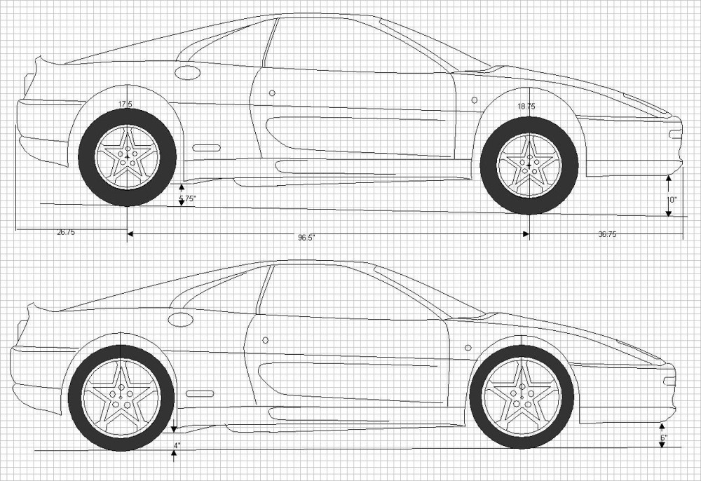
The other thing this test fitting allowed me to do was measure the gap between the top of the tire and the bottom of the fender lip to determine just how much of a drop I would need to fill the wheel wells with the tires. I also played around with some scale drawings I had made to see what the effect of different overall diameter wheels would be in combination with different suspension drops needed to take as much of the guessing out of the equation. Here’s a sample among many I did. The top car is with 16” wheels and 24.5” tall tires without any dropping, and the bottom car is with 18” wheels and 25.25” tall tires, plus a 3” drop IIRC.
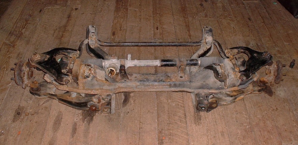
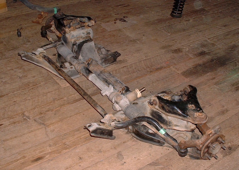
To get the right drop and wheel well fill on the front end, I decided to get HT Motorsports 1.5” drop spindles (since that’s the max they currently make), and fine-tune the rest with adjustable coilovers. (At the moment, I expect to buy 225/45/17's for the front since they have a 25" diameter, but this isn't cast in stone yet.) With my HT shopping list in hand, I ordered the front end components and while I waited, removed and took apart the OEM front cross member. Here it is in all its glorious Canadian weathering (less the springs). This is the view from the driver’s seat:
Here’s another view as seen from the front quarter of the car:
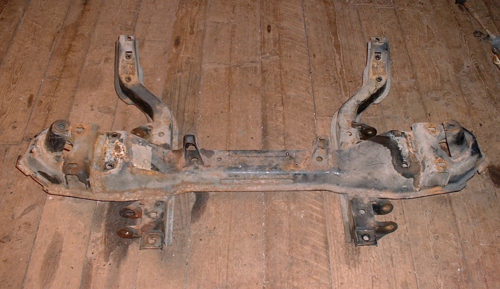
I spent a couple hours getting the suspension components off the cross member, running into the usual problems of seized bushing sleeves, and shearing bolts etc, but here is what I was ultimately after since everything else is going to be replaced:
Next stop: the sand blasting booth (the great outdoors), and the painting booth (the great outdoors)… stay tuned.
Fiero2m8
MAR 18, 10:52 PM
Very nice work Blooze! I'll be watching your suspension progress. I've already decided to cross drill my rear rotors after seeing your posts on the previous page.
I modeled up the 88 rear suspension based on Bloozberry's terrific drawings and work that I've done previously and have done some motion analysis and made some low rez animations. Next time around I'll set the resolution higher and just wait on the rendering.
If you watch it a few times you can see how the wheel toes in as it travels up and down.
Given this a tri-link stut style, there's not much camber gain, but you can help it out by raising the lower links location on the subframe to keep it negative as long as possible.
I can do one with your long links and see what it looks like.
------------------ yellow 88 GT, not stock white 88 notchie, 4 banger
Bloozberry
MAR 22, 12:57 PM
Right on! Now that's cool. I give you a big fat "+".
ccfiero350
MAR 22, 03:11 PM
I'll run the program again with your wide track links, They are +3" each side correct?
------------------ yellow 88 GT, not stock white 88 notchie, 4 banger
Bloozberry
MAR 22, 03:50 PM
Yep, 3" per side, but remember that the strut remains at the same location and angle... the gap between the newly located knuckle and the bottom of the strut is taken up by a solid spacer that you'll have to model either as part of the lower strut or top of the knuckle.
[This message has been edited by Bloozberry (edited 03-22-2011).]


 Been up to my eyeballs (and nose hairs) in stripping the 200 year old plaster and lat walls from the last room in our house that needed renovation. I'll be back on the project car soon though. (oops my wife just reminded me I'm spending quality time with her while we renovate together... I suppose that's not so bad.)
 I’ll be ordering it.
 That means I’ve got precious little time to devote to this thread at the moment. So, in the interests of keeping this thread from falling off the front page, I’ve decided to go a little out of sequence and mix things up a bit.
 I’m going to buy some time, go out on a limb, and post some front suspension pictures hoping you guys can keep what’s-what straight in your heads. This should buy me enough time to eek in a moment here and there between jobs to work on the 6” increased track-width drawings for the new rear and maybe get on with the cradle fabrication. So without further ado…