
 
     |
| Blooze Own: An F355 Six Speed N* Build Thread (Page 36/126) |

|
dhobbs84sc
|
MAR 07, 12:35 AM
|
|
Enough drawing and more working!! I wanna see this baby done! Have you ever watched a movie at 30 second incriments over the course of 3 years? THATS WHAT THIS IS LIKE!!
Lol but the drawings are super helpful (not for me, I have an 84, 85 and an 86) I'm amazed by how paitent you are with this. You don't rush or get overanticipated. That is why I check this build everyday for updates. Keep them coming! Even if they are small. Either way your builds are simply amazing.
|
|
|
|
Nashco
|
MAR 07, 03:56 PM
|
|
As a person who works with CAD every day, I'm really impressed with your drawings. I can't believe you did that all the "old fashioned" way, measuring manually, instead of using a Faro arm or laser scanner or similar. Must have taken a long time, you are extremely patient! Are you doing line drawings or making solids of these? If you can save the CAD files as something in a 3D format (ideally, 2D works if that's all you have), I'll be sure to give them a home on the web for all to use and share. I've been contemplating making a tubular rear cradle on an '88 for Northstar guys as well, so maybe we can join forces and brainpower. You're ahead of me, for sure, but like you said earlier, a few viewpoints can result in better details you wouldn't think of on your own.
Keep up the good work!
Bryce
|
|
|
|
FieroWannaBe
|
MAR 07, 11:29 PM
|
|
I started on the solid modeling of the cradle, this is going to take the longest to make, there are many profile changes and obscure geometries to model, but I'm getting more familiar with the different solid works features I haven't used much in the newer versions.
|
|
|
|
Bloozberry
|
MAR 09, 04:17 PM
|
|
Dhobbs, I know exactly what you mean… I’m getting cabin fever sitting at this computer and am dying to get my hands dirty again.
Nashco: Thanks for the compliment. I wanted to create the drawings in a software package that’s not only available to the masses, but one that everyone operating Windows already has. My drawings were created using Microsoft’s drawing toolbar which can be found under View, then Toolbar menus. I open up an MS Excel file, force the grid lines to squares, then use the drawing tool to create the illustrations. They’re vector drawings so they’re fully scalable and I plan to give everybody access to them eventually. FieroWannabe is one of several who have offered to convert them into 3D as you can see from his latest post. I appreciate your offer to host the source files on your website  but I would prefer to have them here directly on PFF somehow. As for providing constructive input, I’m planning on going through the design exercise right here in the thread to get feedback from anyone who’s interested, so you’re more than welcome to join in… I look forward to your contributions! but I would prefer to have them here directly on PFF somehow. As for providing constructive input, I’m planning on going through the design exercise right here in the thread to get feedback from anyone who’s interested, so you’re more than welcome to join in… I look forward to your contributions! 
Well after this post, I think I’ll have finally done all I’m going to do to map out the OEM rear suspension (only the die-hards will stick with my thread after this one). I’ll be the first to admit that I’m no suspension guru and I’m more than a little wet-behind-the-ears when it comes to suspension dynamics, so please don’t be too harsh on me if I get something wrong. My objective here was to learn something new and try to understand what the effects of HT Motorsports extended control arms would be on my car and improve the characteristics if possible.
I bought what I thought would be a great reference book, Herb Adams Chassis Engineering which is highly regarded by many as the “suspension bible”. Rather unfortunately it was a serious letdown for me on several counts. The rear end suspension section was written with its primary focus on live axles and had very limited analysis of independent rear suspensions. With the vast majority of front-wheel drive cars today using Macpherson strut geometry, I expected there would be a great section devoted to them for front suspensions that I’d be able to apply to our unique cars in the rear. Much to my dismay, the only drawing in the book of a strut type suspension is improperly drawn, poorly explained, and incorrectly labeled. Finally, the book is very thin on details regarding how to calculate many of the interesting characteristics of suspension geometry. Instead, the reader is encouraged to buy a suspension software package and let the program do the work. Not exactly what I expected. So most of what I learned recently came from gleaning tidbits of information from many, sometimes contradictory, sources on the internet (  oh yay). oh yay).
I decided for my most basic analysis of rear suspension geometry, I’d look at five things: swing arm lengths; roll centers; camber changes; toe changes; and anti-squat. Each are discussed separately below, so your own bag of Doritos might come in handy if you plan on sticking with me.
Swing Arms
Understanding swing arms is easy: it’s basically figuring out that the wheels move up and down as though they’re attached to much longer control arms than what they look like. On the ’88 Fiero, which has a Chapman strut rear suspension, the wheels actually move up and down (as viewed from the back) as though they were on levers 7’5” (2.275 meters) long… a far cry from the paltry 1’8” (324mm) long lateral links connected to the knuckle. The first drawing below shows how the virtual swing arm is measured on an '88 Fiero. On a Chapman strut suspension, two lines are drawn: one at right angles to the strut centerline starting at the upper strut bushing (the upper blue line); and the other line through the two pivot points of the lower control arm (the green dashed line), until they intersect way off to the extreme right of the drawing. The intersection is the location of what’s called the lateral Instantaneous Center (IC) for that rear wheel. The length of the swing arm is the distance as projected on the ground from the IC to the centerline of the tire patch. This means that the wheel initially moves through an arc as though it were connected to a lever that pivots at the IC. As you’ll soon see though, the IC moves around as the suspension compresses and extends.
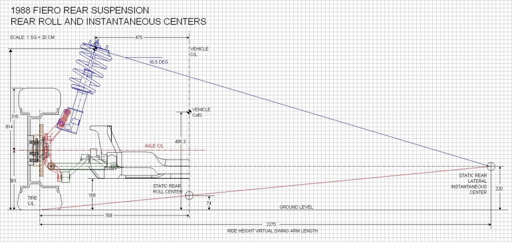
Roll Center
The second thing that can be found once the IC and swing arm are determined, is the rear Roll Center (RC) of the car at ride height. The rear RC is the point about which the center of gravity of the car wants to roll around at the rear. To find the rear RC, all you do is add the red line shown above starting at the center of the tire contact patch and intersecting the IC. Once that’s done, wherever the red line crosses the centerline of the car, that’s where the rear roll center is located. For the Fiero, it’s 74 mm (2.9”) above the ground with the suspension at ride height. According to Herb Adams, “Most successful cars have the roll center height between 1.00 inch below the ground, to 3.00 inches above the ground” so 2.9 inches seems acceptable.
Here’s where it gets a little more complicated, and the drawing a lot more busy. As mentioned earlier, the instant center for the rear of the car changes location since one of the lines used to determine where it’s located, is drawn through the lower control arm. As the lower control arm pivots through its range of movement, the IC and RC will move around with it. To see the effects of that when the ’88 Fiero suspension goes through 3” (76mm) of jounce (blue lines), and 3” (76mm) of rebound (red lines), I replicated the components, rotated them, and added them to the above drawing to create the drawing here:
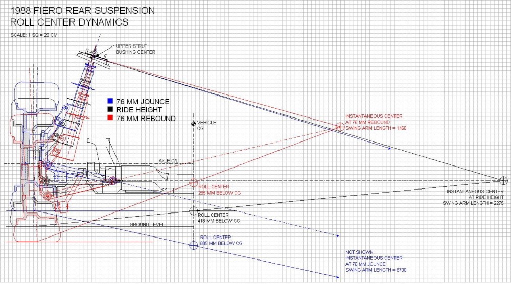
I know it’s a mess of lines, but it’s a lot simpler if you focus on one color at a time. Starting with the blue jounce lines that angle towards the lower right hand of the drawing and end in arrows, the swing arm length gets so long that I had to calculate its length because the software wouldn’t allow me to make a drawing that large. It went from 2275mm at ride height to 8700mm! Using the same method to find the new roll center as above, the RC drops to below the ground level and further away from the car’s center of gravity by (585mm - 418mm) = 167mm or 6.57” as compared to the location at ride height. A better design would keep the distance between the RC and CG more constant throughout the suspension travel according to Herb Adams. He also says that “reducing the distance between the RC and the CG will reduce roll angle, which leads many racers to want to raise the RC. But a higher RC causes jacking effects and erratic suspension movements”. Instead, “…roll angles can be controlled with stabilizer bars, front and rear, so there isn’t the need for the roll resistance that a high RC gives.” Keeping the RC at a constant height is more important than reducing its distance to the CG.
In rebound (the red lines) on the other hand, the swing arm is reduced fairly significantly causing the roll center to rise up towards the center of gravity by (418mm – 285mm) = 133mm or 5.24”. This would happen in one of two circumstances: either after going over a big bump and the car getting airborne, or on the inside wheel while going around a fast corner. In either case, the wheel is unloaded dramatically and from what I could glean, has little effect on the car’s handling in this extreme case.
Camber Change
The third on the list of basic suspension characteristics is the amount and direction that wheel camber changes as the suspension moves through its range of motion. Camber is the tilting of the wheel vertically as viewed from the front or back of the car. As a vehicle turns a corner, the body rolls toward the outside of the turn and the weight transfer compresses the outboard suspension. If the wheel were to stay perpendicular to the side of the car when it did this, the tire contact patch would tilt away from the pavement onto its outside edge and lose cornering grip. A good suspension design causes the outboard wheel to tilt progressively more inwards at the top to keep the tire contact patch in full contact with the pavement as it compresses. This is called camber gain under jounce. The reverse is true for the inside wheel. Herb Adams book states that one of the main limitations of a Chapman/Macpherson strut suspension is that the design is inherently poor at providing decent camber gain.
To see the effect of suspension compression on camber, once again, the rear view drawing comes in handy, with a few notes to observe: I don’t show the cradle roll angle in either direction for clarity’s sake; and at ride height (black lines), I drew the wheel with zero preset camber, when in reality, the alignment specs call for minus 1 degree:
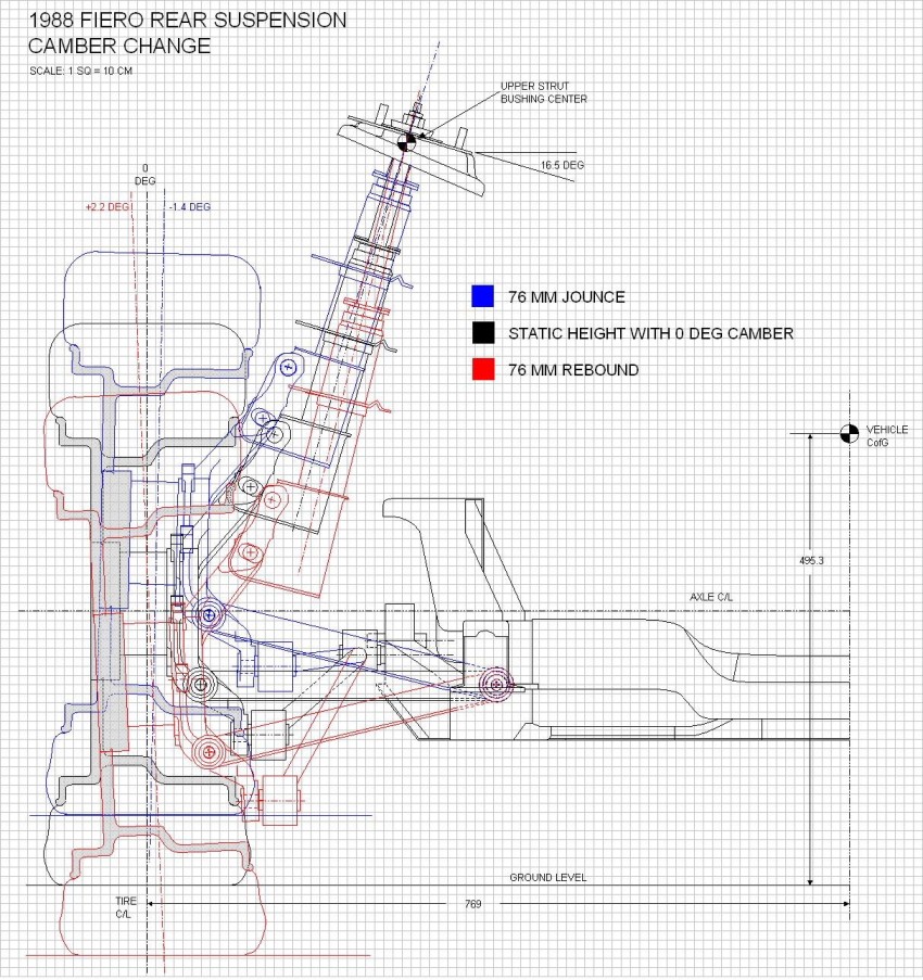
From the tilting of the wheel centerline you can see the OEM suspension does indeed react the way it should, that is: the wheel gains 1.4 degrees of negative camber under compression and 2.2 degrees positive camber under extension. In Herb Adams example, his car gained 2.7 degrees in negative camber at 3” of compression, and was basically at zero camber gain in extension. For the best traction around a corner, the camber change should come close to matching the angle of body roll to keep the tire perpendicular to the ground. Without a stabilizer bar (anti-roll, swaybar, whatever) to help to keep the body roll angle down, it appears our little cars would suffer rear cornering power loss due to the limited rear camber gain.
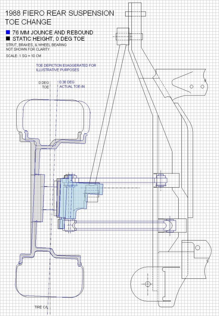
Toe Change
The fourth characteristic I wanted to study was the change in rear toe as the rear suspension moved through its arc or travel. Toe is the amount of rotation the wheels take on in the steering axis as viewed from the top of the car. To quote Herb Adams “ Bump and roll steer are really the same thing. What they refer to is the amount and direction that each rear [wheel] might cause the car to steer as it moves through its travel. Even slight changes in the alignment of the rear [wheels] will cause big changes in the direction the car will go. The preferred design characteristics are very little roll steer, and if there is any, it should be in the understeer direction.” For an independent rear suspension “…roll understeer is obtained by having the wheels toe-in as they go up into jounce.”
To visualize what happens on the ’88 Fiero rear end, I used the top view of the suspension drawings I made earlier. To ensure that the rear wheels toed-in on the Fiero under jounce, GM made the forward lateral link shorter than the aft link. The reason this works is because the shorter forward link will cause the front of the knuckle to pull inboard faster than the longer aft link when they are pivotted upwards. I redrew the two lateral links as they would be seen from above, once their angles had been raised to the 3” jounce position (lines in blue). The difference in their effective lengths was only 1.0mm so I needed to calculate the change in toe using basic trigonometry rather than by trying to measure it on the drawing. I grossly exaggerated the change in toe on the drawing to demonstrate the effect of jounce. The actual toe change is about 0.38 degrees toe-in, which seems to meet the requirement stated by Herb Adams above.
Anti-Squat
Finally, the last characteristic to be studied is anti-squat. Squat is the tendency for the rear of the car to lower as the weight transfers rearward under acceleration. Anti-squat is a suspension characteristic that opposes this tendency, increases rear tire loading, cornering power, and traction available for acceleration. With a live axle, the suspension can be designed to provide 100% anti-squat, but unfortunately for us, the use of an independent rear end limits the amount of anti-squat to around 25%.
Calculating anti-squat for an independent rear end is one area that Herb Adams book didn’t cover very well in my opinion. After a lot of internet searching, I finally found a formula that allowed me to calculate it for a Chapman strut rear end. It involved determining the longitudinal instant center (IC) for the rear suspension by drawing a line (green dashed) through the rear trailing arm angle and extending it forward until it met up with another line (blue) drawn perpendicular to the strut centerline, at the upper strut bushing. Once the IC was located, a third line (red) was drawn between the center of the axle to the IC. The angle of this red line to horizontal (7.85 degrees) was then used in a formula that included the height (H) of the car’s CG and the wheelbase. (I apologize for the small scale of the drawing but PiP has a 1020 pixel limit on the width of pictures) (edited to correct formula and resultant anti-squat value in image below)
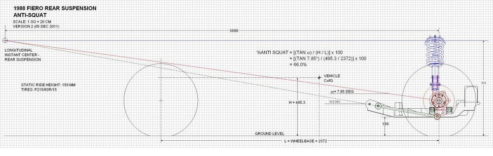
From the calculation on the drawing, you can see that the ’88 Fiero appears to have about 66% anti-squat. Interestingly, Herb Adams states that 25% is the practical limit for an IRS. some of you might have already figured out, increasing the angle of the red line would result in even greater anti-squat, so I explored that a little.
The only way to increase the angle of the red line is to shorten the longitudinal swing arm by either increasing the angle of the trailing link, lowering the top of the strut, or some combination of the two. Shortening the strut would give less suspension travel so you would need stiffer springs to prevent the car from bottoming out on the struts. The alternative, ie raising the angle on the trailing links seems more feasible, but the trailing link is the component that transfers the forward accelerative forces to the frame. The more angled the trailing link is to the ground, the larger the vertical component of the acceleration force becomes. At some point, the angled trailing link will cease transferring the accelerative forces forward into the frame and instead cause the wheel to try to walk under it, stressing the lateral links in the process. According to Herb, too short a longitudinal swing arm will also result in rear axle hop during braking, but he doesn’t quantify this in any sense.
Whew! A marathon post with lots of reading. This will separate the comic book readers out from the techies.  I give two thumbs up to anyone who got through it all and understood it. As I said, I’m hoping this post stirs up some discussion since now is the time to get the theory right before I start applying the logic to the new design. I give two thumbs up to anyone who got through it all and understood it. As I said, I’m hoping this post stirs up some discussion since now is the time to get the theory right before I start applying the logic to the new design.
(Edited to correct formula in anti-squat diagram above, resulting in an increase in anti-squat from 28% to 66%.)[This message has been edited by Bloozberry (edited 12-05-2011).]
|
|
|
|
Zac88GT
|
MAR 09, 07:57 PM
|
|
|
Wow, great information. It'd be interesting to see the roll center lateral migration under body roll as well, I suspect it's quite high.
|
|
|
|
cptsnoopy
|
MAR 09, 10:23 PM
|
|
Hey Blooze,
I don't really understand all that stuff very much but your work is helping me get some clue. Thank you!
Charlie

|
|
|
|
aaronkoch
|
MAR 09, 11:41 PM
|
|
Looking at your roll center picture, quick question:
So, the lower the C of G of the car, or more precisely, the closer the static roll center is to the CG, the less tendancy the car has to lean when cornering?
In theory, if the roll center was precisely AT the center of gravity, the car would corner perfectly flat without swaybars, right? I know this is really impractical, but a fun mind excercise.. I suppose if you had really tall wheels on a car that was lowered to the point where the CG was UNDER the center of roll, you could theoretically make a car lean INTO a turn. Cool.
------------------
Currently in the middle of my 88 + 3800NA swap
|
|
|
|
dhobbs84sc
|
MAR 10, 04:39 AM
|
|
From what you said, my understanding is, If you increase your anti-squat you have a better chance of lifting the front wheels? And I doubt thats good on daily driving...
But I'm kinda lost lol. 2nd time around I read slower [This message has been edited by dhobbs84sc (edited 03-10-2011).]
|
|
|
|
Bloozberry
|
MAR 10, 10:32 AM
|
|
| quote | Originally posted by aaronkoch:
So, the lower the C of G of the car, or more precisely, the closer the static roll center is to the CG, the less tendancy the car has to lean when cornering?
|
|
Yes that's right Aaron, it would act as though the car were going around a banked oval. Instead of being thrown sideways in the car as you turned the corner, you would instead feel yourself being pushed down into your seat.
| quote | Originally posted by dhobbs84sc:
If you increase your anti-squat you have a better chance of lifting the front wheels? And I doubt thats good on daily driving...
|
|
No... just the opposite. If you study the simplified drawing below, you'll see how anti-squat works. In the top picture, the torque from the turning wheels applies a lifting force on the end of the long swing arm. In this case, the reactionary force is applied ahead of the CofG of the car so it rotates the car backwards causing squat. In the lower drawing, the reactionary force is appplied behind the CofG and forces the weight to be transferred to the front of the car. 100% anti-squat happens when the reactionary force is applied through the GofG. Since anti-squat is measured as a percent, anything less than 100% means that the force is being applied ahead of the CofG, and anything over 100% means that the force is being applied behind the CofG.
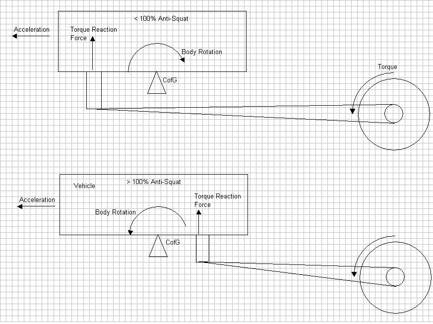
Edit to add definition of 100% anti-squat.[This message has been edited by Bloozberry (edited 03-10-2011).]
|
|

|
ccfiero350
|
MAR 10, 03:49 PM
|
|
The drawings are just great, and a lot of man hours. I agree that there should be a repository for just for CAD files some where here in PFF.
One of the best books I have found on suspensions is "Race Car Vehicle Dynamics" by Milliken & Milliken ISBN 1-56091-526-9 , It's published by the Society of Automotive Engineers and you can get it on Amazon.
And it covers tri-link struts like ours.------------------
yellow 88 GT, not stock
white 88 notchie, 4 banger
|
|
|
|