
 
     |
| Blooze Own: An F355 Six Speed N* Build Thread (Page 35/126) |

|
fieroguru
|
FEB 14, 07:32 AM
|
|
If you can install those strut adapter upside down from your original method, you would lower the rear by the distanct between the bolts.
On traditionally lowered 88's, it is pretty easy to bottom out the strut internally... especially with heavier engine swaps. Flipping the upper strut bushing (at the strut tower) helps some by moving the top of the strut shaft up about 1" and your adapters moving the base of the strut down could help even more.
I would love a copy of your F40 drawings if you are giving them out... fieroguru@lycos.com
Keep up the good work!
|
|
|
|
355Fiero
|
FEB 15, 02:18 AM
|
|
Blooz;
I see what you mean on the adaptors. I would say I am 100% wrong and you need to put them back the way you had them. I made my own but when I saw the adaptors from others the strut always looked lower. In talking to others, they also said that the adaptors lowered the strut down. The pics you show clearly will not work the way I suggested so my apologies for giving you more work than you already have.......
Cheers
Don
|
|
|
|
Bloozberry
|
FEB 23, 04:59 PM
|
|
Thanks for your kind words there Katatak, and for the advice Fierobsessed, 'Guru, and 355. I am now seriously thinking about redesigning those strut adapters to take advantage of idea to regain some strut travel. That's something I would probably not have thought of on my own. 
Well it’s been two weeks since I last posted an update here, but that’s not because I’ve been slacking off. I’ve been busy entering more digital drawings into my computer, saving lots of money not having to heat my shop much this winter.
If you’ve been following along, I realized early on that to design a new cradle for the N*/F40 combination would be silly if I didn’t take advantage of the opportunity to study if improvements were possible as well. The problem with improvements is that you need to have a baseline from which to compare whether your modifications are indeed better or not. It sounds easy, but in reality, none of the Fiero engineering or technical data was released as far as I’m aware, so baseline geometry information remains a mystery to most of us. I hope to fill a little of that black hole by reverse engineering the drawings for the stock configuration as a starting point.
To start the ball rolling, I’ve decided to draw out all of the stock suspension components starting with the ’88 rear. I admit that the accuracy of my drawings is a limiting factor, since most measurements have been taken with calipers, rulers, bubble levels, and squares, not lasers, but they should be good enough to make comparative assessments for most suspension tweaks nonetheless. I also hope to use the drawings later on to create a visual guide to help people determine whether different diameter, width, and offset wheels will interfere with different combinations of coilovers, OEM springs, lowering, etc. (It would be nice if PFF had a repository for such reference material once it's done… hint hint Cliff.) But for now, I have a more selfish goal. 
So for starters, here’s the ’88 rear knuckle:
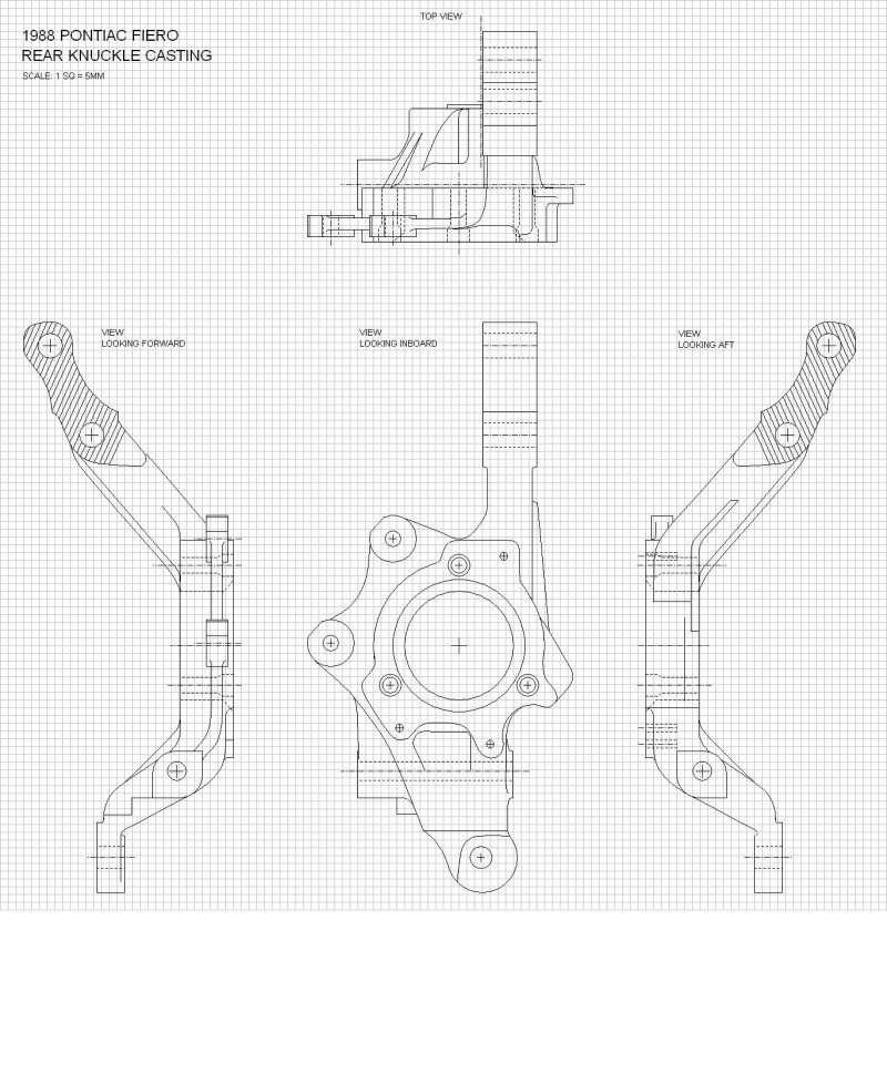
The rear strut assembly proved to be a bear to draw out accurately, but I think I finally have it reasonably precise. The two biggest issues I ran across were the fact that the OEM strut I have to work with, has a worn out top bushing which I only realized much later. This skewed many of my measurements since the top hat was sitting crooked.  I thought it was supposed to be like that. The other issue was that since I drew it from the bottom up, I originally assumed that the spring's axis was aligned with that of the struts, only to find that the top hat would not line up with the top of the spring once I got to that point. I thought it was supposed to be like that. The other issue was that since I drew it from the bottom up, I originally assumed that the spring's axis was aligned with that of the struts, only to find that the top hat would not line up with the top of the spring once I got to that point.  It turns out the spring is actually offset towards the center of the car on the strut, presumably to give more room for the rear tire. Here’s the finished product in the uninstalled height configuration: It turns out the spring is actually offset towards the center of the car on the strut, presumably to give more room for the rear tire. Here’s the finished product in the uninstalled height configuration:

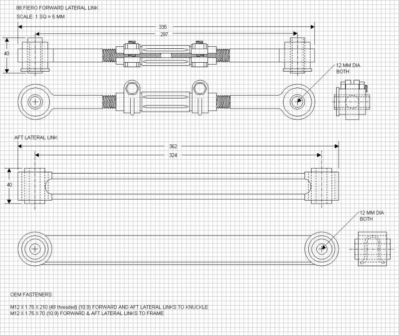
The last thing I drew out was the suspension links. They weren’t difficult, luckily, since by that time my eyes were starting to get tired of focusing two feet away at my computer screen for the last two weeks. These are the lateral links:
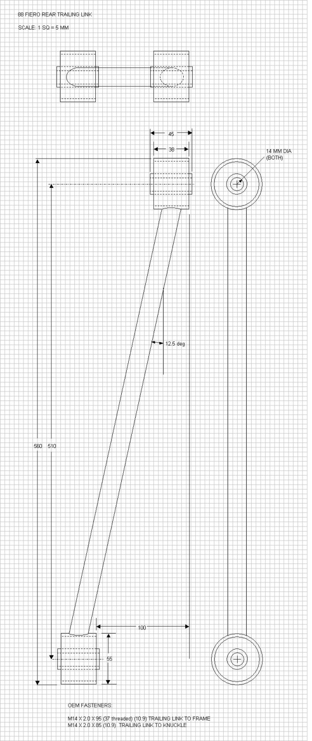
And here's the trailing link:
I’ve already combined all of these components onto a master drawing combining the earlier cradle and the F40 tranny drawings. I need to determine a few things yet like the height of the spring at curb weight which means trying to determine the height of the underside of the strut tower mounting surface in relation to some fixed reference point on the cradle. The chassis alignment data in the service manual is lacking in this area. That will be a challenge to measure I think, but I’m determined. More to come.
|
|
|
|
doublec4
|
FEB 23, 06:24 PM
|
|
|
Your meticulous documentation of everything is mind blowing. lol
|
|
|
|
fieroguru
|
FEB 23, 07:14 PM
|
|
WOW!
Thanks for taking the time to document the F40 and the 88 suspension bits!
|
|
|
|
Bloozberry
|
MAR 04, 01:28 PM
|
|
As always, I appreciate your feedback doublec4 and fieroguru . You guys are doing some amazing stuff in your own respective threads too. It's great to see people stretching or contributing to the envelope of Fiero knowledge 23 years after its demise.
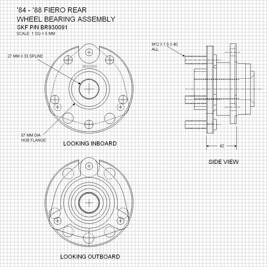
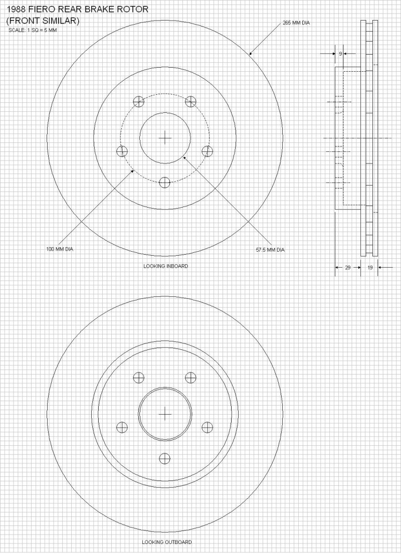
Moving right along, I completed drawing the final suspension components to allow a digital reconstruction of the entire rear suspension system. The last pieces were the wheel bearing assembly (which is identical to all year Fiero's), the brake rotor, the 15" x 7" (ET 30) wheels, and P215/60R/15 tires. I didn't bother drawing out the wheels and tires in great detail nor separately, but chose instead to add them to the master drawings. So for starters, here is the rear wheel bearing assembly (this is SKF part):
And here is the rear rotor ('88 rotors are identical fore and aft):
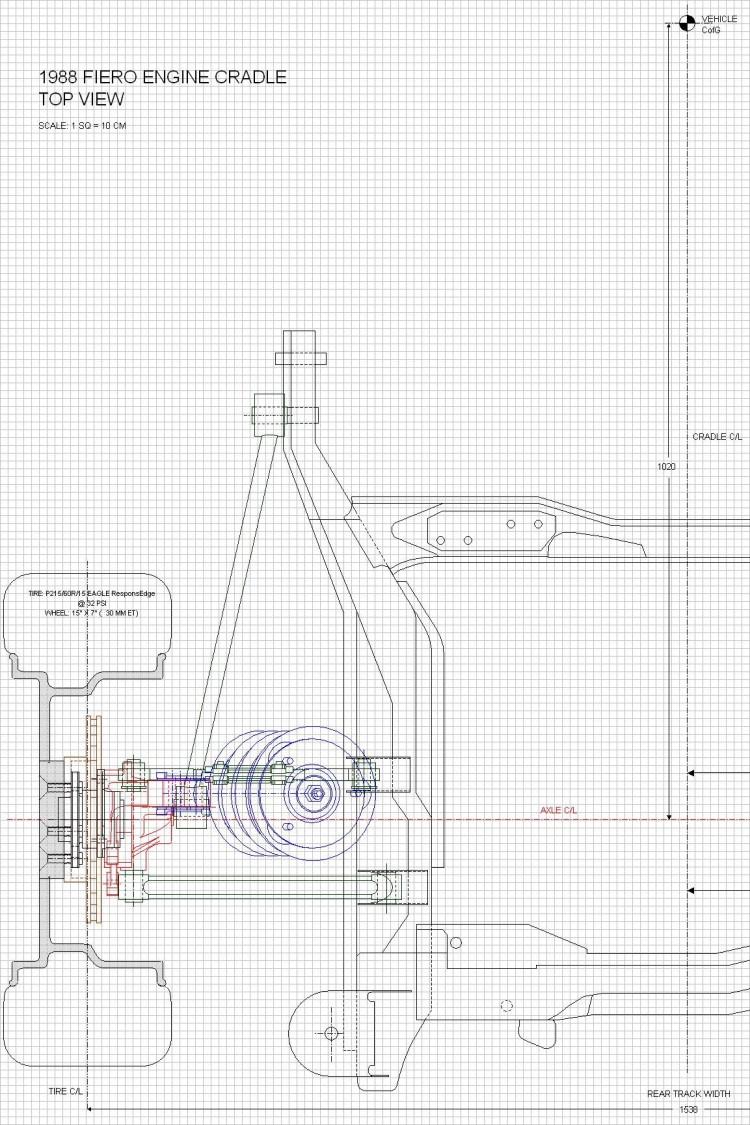
With these last parts drawn out, I combined all the previously drawn parts onto a single set of drawings depicting the rear suspension system in it's entirety. The precise location of the top of the rear strut wasn't an easy measurement to take, but I cross-referenced the dimensions from my own '88 project car chassis and those taken from an '88 GT stored here for the winter. Here are some sources of info regarding some of the dimensions:
1. the location of the center of Gravity (CofG) of the car in the vertical plane was taken from Road & Track Magazine, Sep 1983, in the article Pontiac Fiero Introduction from the Technical Analysis section. Although this was specifically for the '84 four cylinder car, I assumed the height of the CofG didn't change much, of at all with the introduction of the V6;
2. the horizontal location of the car's CofG was calculated based on the reported front to rear weight distribution (47%:53%) from various magazine sources testing cars with the V6, namely: Road & Track Oct 87, Automobile Magazine March '87, and Car & Driver Feb '86.
3. the ride height of the car (ie ground clearance of the cradle) was a rather fuzzy measurement to take empirically given the variables (tire heights and spring sag to name two.) So I referred to the trusty ’88 service manual but found problems there too. It gives the ride height in a table on page 3-16 but the accuracy of the numbers is contestable, since the ride height doesn’t seem to change despite three different listed tires sizes. There is a 4.5 mm difference in the radius between the tallest tire (215/60/15) and the shortest tire (195/70/14) listed, yet the ride height remains the same according to the manual. To get even more conflicting info, I referred to various magazine articles which stated the ground clearance as anywhere between 5.4” to 6.0”. In the end, I decided to let the ground clearance set itself by drawing the lower lateral links parallel to the ground, and add the P215/60R/15 tires digitally onto the hubs. The dimensions for the installed tires came from two different sources averaged out: the stored ’88 GT with brand new Goodyear Eagle Triple Treads, and my own ’86 GT with 1500 miles on Goodyear Eagle ResponsEdge tires at 32 PSI. Final clearance = 6.25"
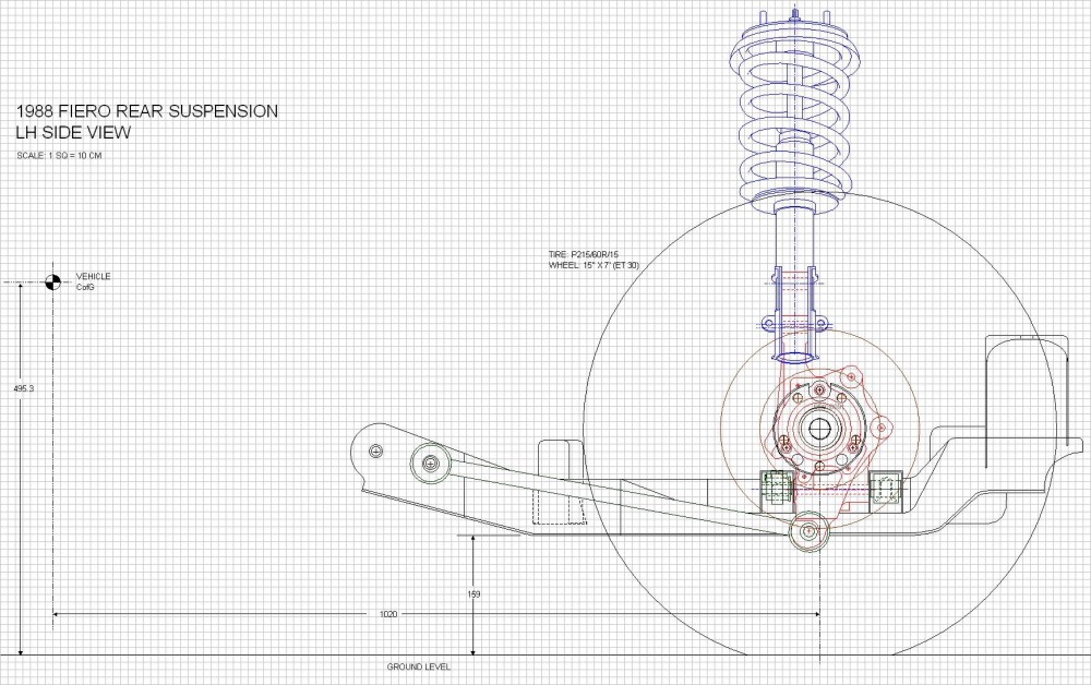
I think that’s all that needs to be explained regarding the sources of information contained in the drawings below, but if you have doubts or questions, please don’t hesitate to ask. I would rather have someone point out an error than continue promulgating it. The next step is to determine the key OEM suspension characteristics such as the instantaneous centers, the roll center, percent anti-squat, etc. I’m armed with Herb Adams book Chassis Engineering  , the internet, and a bag of Doritos to help refresh me in that department For now though, here's the top view: , the internet, and a bag of Doritos to help refresh me in that department For now though, here's the top view:
The rear view:

And finally the side view:
|
|
|
|
aaronkoch
|
MAR 04, 04:44 PM
|
|
This makes me love you. No, I mean it. I've been looking for drawings/measurements like this, but am far too lazy/incapable to do them myself. A plus to you, kind sir.
------------------
Currently in the middle of my 88 + 3800NA swap
|
|
|
|
dobey
|
MAR 05, 02:46 PM
|
|
|
Wow. Those are some nice drawings indeed.
|
|
|
|
FieroWannaBe
|
MAR 05, 09:33 PM
|
|
|
Bloozberry, I had sent you an email a week ago, I am just wondering if you received it. If you didn't, I am hoping you would not mind sharing your hard work with me, I just finished up my degree, giving me much more free-time to take your drawings and create some solid models of your drawings.
|
|
|
|
Bloozberry
|
MAR 06, 10:18 AM
|
|
Hey, thanks there aaron and dobey (although I won't believe that you love me aaron until I see a box of chocolates  )! Even though drawings aren't as exciting as pretty pictures, I knew some people wouldn't mind a quick detour into the nuts and bolts behind the suspension. )! Even though drawings aren't as exciting as pretty pictures, I knew some people wouldn't mind a quick detour into the nuts and bolts behind the suspension.
For Fierowannabe: I replied to your email today.
|
|
|
|