
 
     |
| Blooze Own: An F355 Six Speed N* Build Thread (Page 34/126) |

|
ArbinShire
|
JAN 31, 12:58 AM
|
|
| quote | Originally posted by Bloozberry:
Well, cptsnoopy and doublec4 figured it out. I haven’t a clue what ArbinShire or fierogt28 were thinking. Weren’t you guys paying attention about the part with the HT Motorsports 6" track width tubular control arms? Or when I mentioned the spacers were for sale? I’m starting to think you guys are just looking at the pretty pictures.  |
|
D'oh! I didn't catch that. +1 for doing it the right way!
|
|
|
|
Bloozberry
|
FEB 07, 08:00 PM
|
|
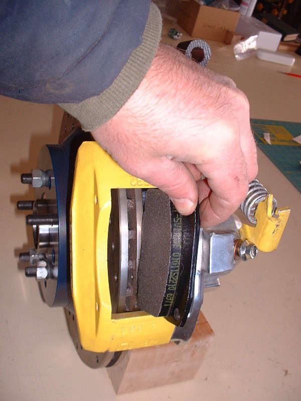
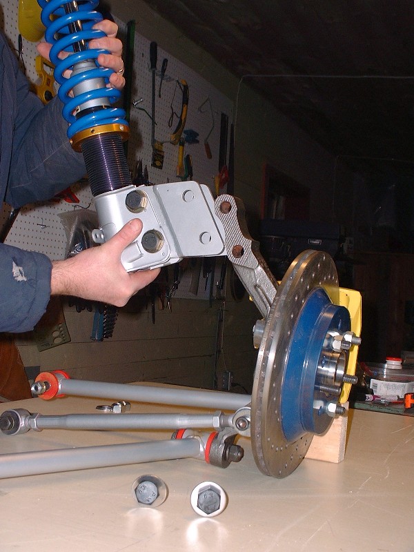
Well I’m running out of rear suspension build-up photos so this will be the last rear suspension post until these parts meet up with the new cradle. I left off the last time ready to install the brake pads so here’s a few pictures covering that aspect. The first one here shows that there are differences between the inboard and outboard pads. The pad on the left is the outboard one and is differentiated from the inboard pad by the lack of the two pegs in the middle of the steel facing seen on the right hand pad. These pegs fit into corresponding dimples in the face of the piston, so the piston must be rotated to have the dimples aligned vertically in order for the inner pad to fit.

When I first tried to install the inboard pad everything was hunky-dorey but when I tried to fit the outer pad into place, there wasn’t enough room even after jimmying the caliper on the sliders to give as much space as possible. At first I thought I’d have to shave the pads down a bit but then got to thinking the piston didn’t look fully retracted. After taking off the e-brake lever and trying to push, rotate, squeeze and use every other possible method of recessing that piston into the caliper some more, I unscrewed the bleeder valve to have a look down the hole. Everything was clean, and by chance, I tried squeezing the piston in further while the bleeder was out and it slid in easily another 3/16”. I discovered that the bleeder valve was screwed far enough into the bore (without the banjo fitting) that it was preventing the piston from retracting fully. Duh!
The extra room was all that was needed to slip both pads in with space to spare. So then came the bail wires, and finally the two roll pins keeping everything together. The roll pins are a press-fit into the aluminum half of the caliper so a couple taps with a small hammer and a punch is all that it takes to seat them.

I decided to build up the rest of the rear suspension off the car so next up was installing the two lateral links. On the ‘88’s, they’re held on to the knuckle with a single M12 X 1.75 X 200 bolt passing through a drilled passage in the lower knuckle. This knuckle hole is notorious for becoming out-of-round and allowing some slop in the bolt, causing problems. Mine were still nice and tight; though I blew them clean with the bead-blaster to clean out the little bit of rust hanging around in them. I ordered new bolts in the smallest order quantity possible for these 12.9 grade bolts (a box of 12) for $100. I actually bought them 220mm long since that way I could cut off 20mm for the rear bolts and use the rest as spares for the hard-to-find pre ’88 front upper control arm pivot bolts as well. I greased them up with anti-seize compound before installing them.

Then slipped the forward adjustable lateral link onto the bolt, then the bolt through the knuckle, and the rear fixed lateral link on the other side.
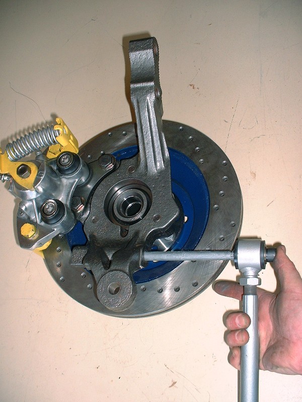
The nut gets torqued on with 37 lbft first, then turned another 90* for the proper torque. Here I was just getting things snugged up.

After the lateral links, the trailing link was next. At the knuckle it takes an M12 X 1.75 X 65 (9.8) bolt and nut torqued to 44 lbft. The eagle-eyed among you will notice that in this picture, I’m installing the trailing link facing backwards. No biggie, I just swung it around to face the right way in later photos!
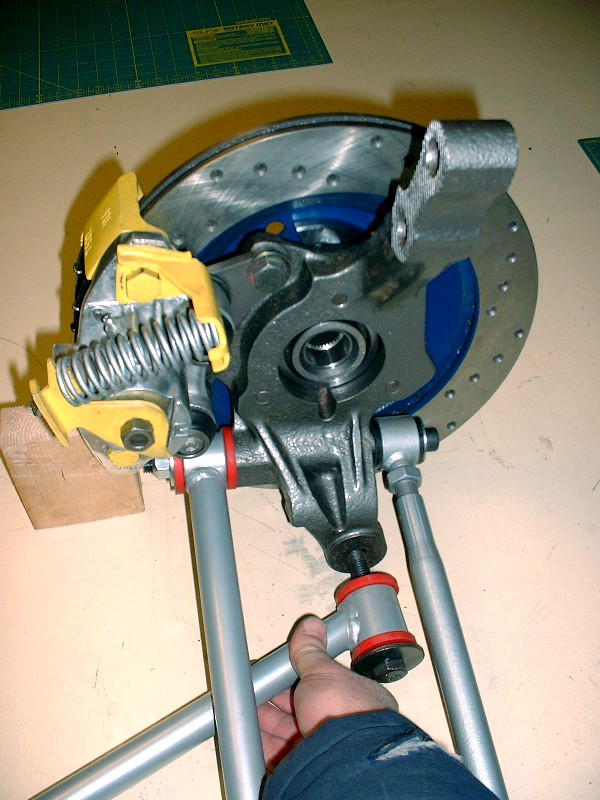
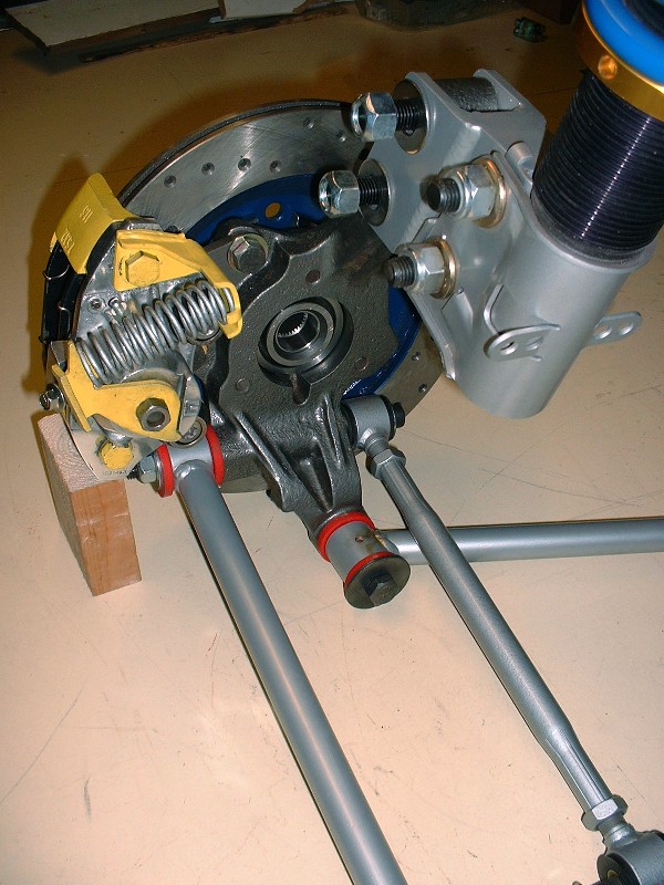
Here’s the LH knuckle with all three links attached and again, the eagle-eyed among you will notice that I installed the RH trailing link on the LH knuckle… the telltale sign is that the grease zerk fittings should be on the bottom where they’ll be accessible. I’ll change them around another day.
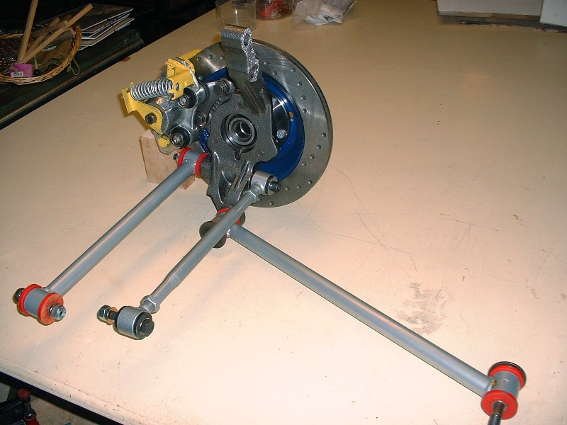
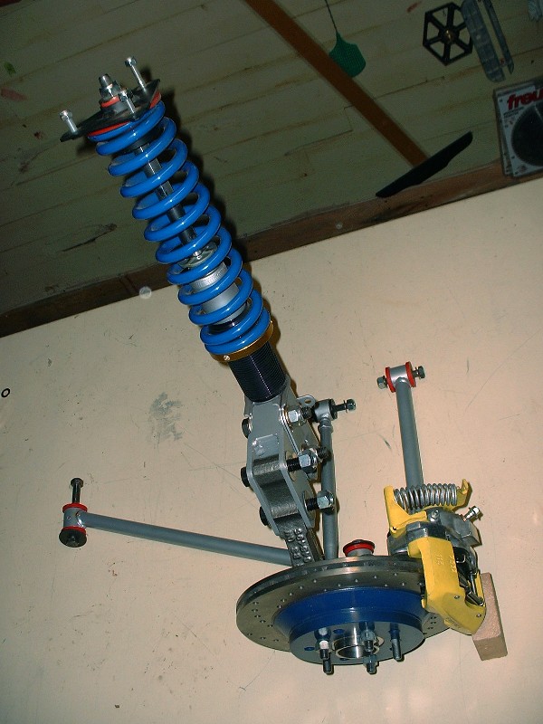
The last item to be installed was the strut. I’ll probably need to remove them later to install the suspension in the car, so I only installed them loosely for the pretty pictures. It’s held on to the top of the knuckle with huge M16 bolts.
Here’s a close up of all the links attached to the knuckle:
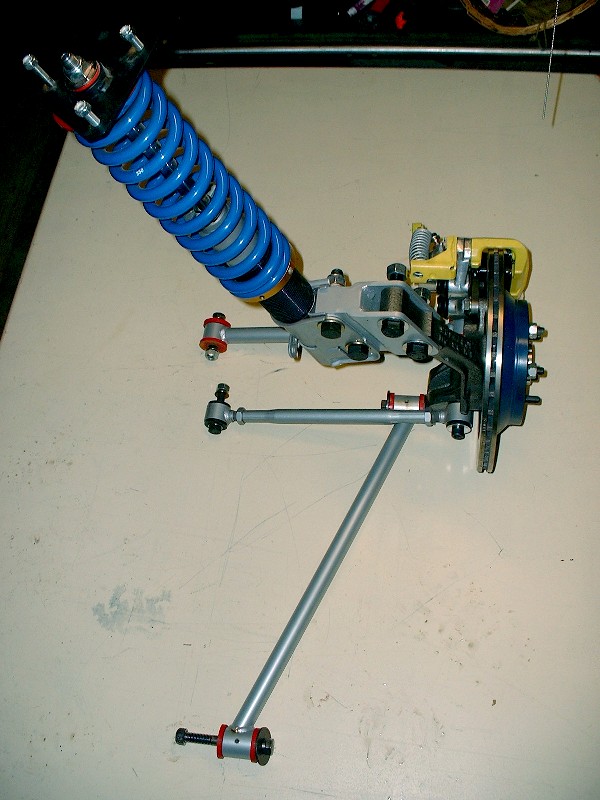
And finally a couple shots of the whole rear suspension for the LH side. I should weigh it, but I’m afraid of what the scale may say!
|
|
|
|
BtotheB
|
FEB 08, 10:32 AM
|
|
Wow, that's pretty...
Your attention to detail is inspiring! I find myself taking my time more often on my winter projects to get things done right. My skill level is nowhere near yours though, but hopefully my results won't be embarrassing at least.
This is my favourite build thread, partly because of the regular updates! Keep it up..
Brad
|
|
|
|
355Fiero
|
FEB 08, 11:25 AM
|
|
Blooz;
You will want to turn those adapters on the struts over so the strut hangs lower than the knuckle mount. The 355 body kit you have will want the frame quite a bit lower to fill the wheel well properly so having the adapters your way will raise the frame compared to old not lower it. The other way allows for more strut travel compared to your orientation.
Rear setup looks really good.
Keep it up.
Don
|
|
|
|
Tinkrr
|
FEB 08, 11:33 AM
|
|
Great work!
One question, will the strut bolts be long enough to acomodate the sway bar bracket?
|
|
|
|
Bloozberry
|
FEB 08, 12:48 PM
|
|
Thanks BtotheB (..must be short for "Brad to the Bone" ). Have you got a thread started yet? Canadian winters are perfect for spending long dark days detailing away at things!
For Don: Thanks for pointing out the strut adapters should be turned the other way... I'm not sure I would've clued in on that, but it makes perfect sense. I don't want to have to dial out any more height to the suspension than I'm already having to deal with!
For Tinkrr: The bolt length is another good question since I had overlooked the sway bar until now. I'll check it out later today and report back whether they're long enough or not, and post the details about what dimension bolts are needed. Good eye!
I just knew there were some hawks out there!
|
|
|
|
Fierobsessed
|
FEB 09, 01:38 PM
|
|
|
Since you are running poly, I'll recommend that you put a jam nut behind the nut on the long bolt through the knuckle. Many people found that the poly causes the crush nut to work itself loose, even when torqued properly. Even a slight loosening of the nut will cause the toe to move a lot.
|
|
|
|
Bloozberry
|
FEB 13, 09:22 PM
|
|
Thanks for the suggestion Fierobsessed. Do you still think jamb nuts are required even with prevailing torque nuts (lock nuts)?
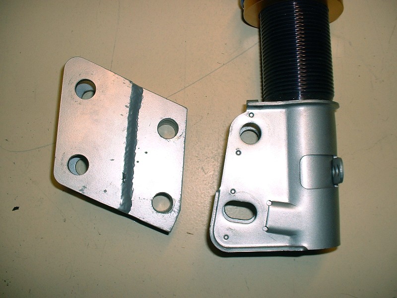
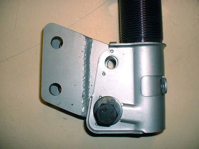
Well Don, I played around with the strut adapters like you suggested and something just doesn’t seem right with them turned the way you suggested. I’m not saying that you aren’t right, but it just doesn’t look like these adapters were made the same as yours… have a look. This is what the adapter looks like on the knuckle with the adapter on the original way I had them:
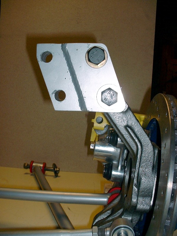
And this is with the way you suggested. It just looks awkward.
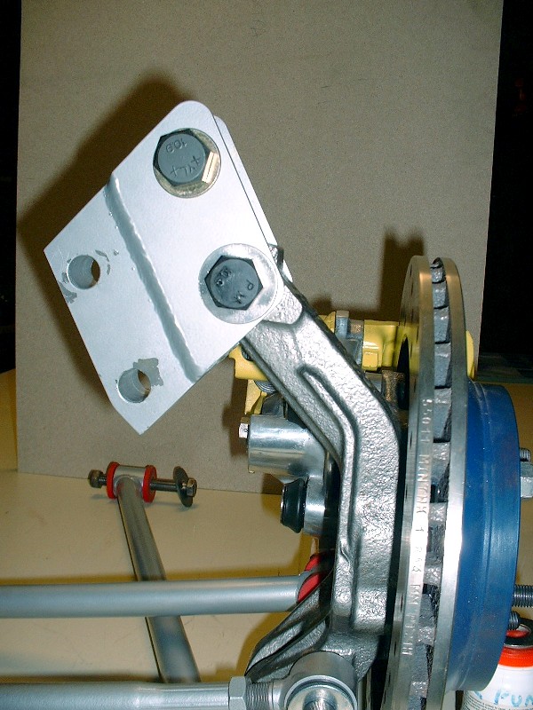
And this is the orientation when installed on the strut the way I originally had it:
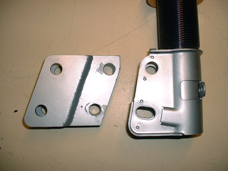
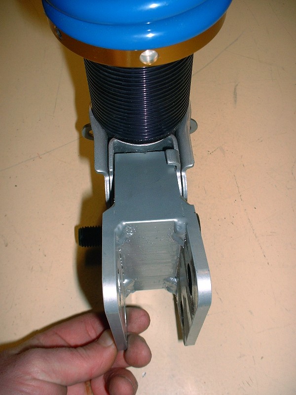
…versus the way you suggested:
Beyond the optics of the two orientations, when I tried to install the adapter to the strut the way you suggested, I ran into interference problems. Here’s a picture to show what I mean… I couldn’t get the upper holes to line up enough to get the bolt through:
The interference is between the top of the adapter and the strut body. I would probably have to grind off 3/16” or so off the top of the adapter to rotate it far enough to get the holes to line up. To me, it just doesn’t make sense to install it your way. Installing it the original way I had it won’t raise the car in the rear like you thought. Perhaps one of the photos in my earlier posts gave that illusion, but the adapter will line up straight across, neither raising nor lowering the rear.
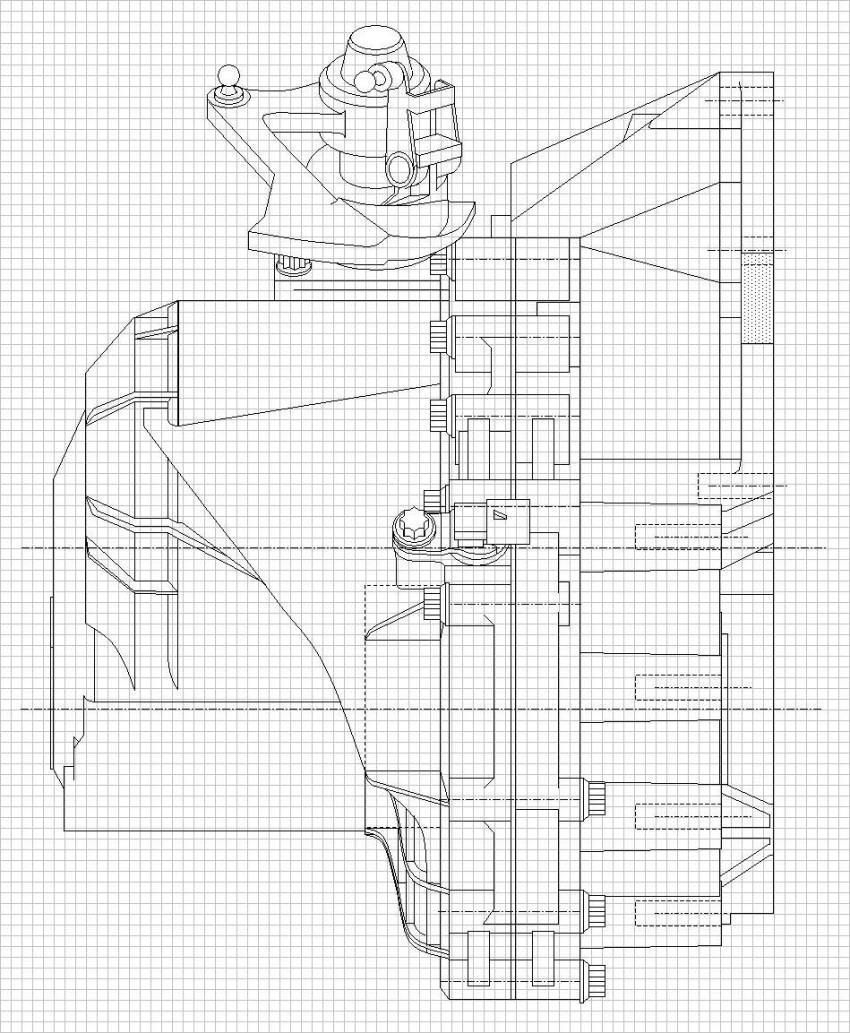
So then, on to new things. I’ve finally finished entering the dimensions of the F40 transmission digitally to help me redesign the cradle. Before going through this trouble, I searched far and wide on the internet, at dealerships, machine shops, etc, and made countless calls to GM trying to find someone to release scale three-view drawings of the F40 and the Northstar to no avail. For a while, I thought that I would get something from GM Customer Services, but at the last moment they said they weren’t permitted. Rats!
So here’s the fruit of far more hours of labor than I dare to admit. Each square represents 5mm. I’ll post high resolution drawings of the transmission when I’m finished working up the cradle drawings. It would be nice if Cliff could create a section on the forum for reference drawings like this. Currently I’m working up the rear knuckles, trailing and lateral links too. So here’s the three view… admittedly low rez to get PiP to accept it:
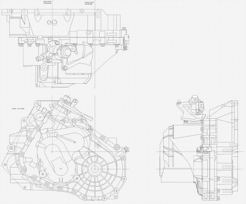
And here are some higher resolution pics of each view separately starting with the end view:
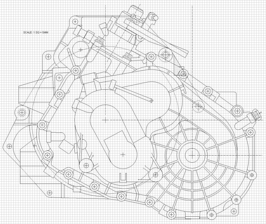
Top view:

And Rear view:
|
|
|
|
katatak
|
FEB 13, 09:47 PM
|
|
Truly a work of art Blooz! I wish I had the patience - and talent to get to your level of attentoin to detail. Very nice work you are doing. I am truly amazed. I'm pretty sure I said this somewhere else in the thread but I'll say it again. Thanks for sharing your hard work with the rest of us.
Pat
|
|
|
|
Fierobsessed
|
FEB 14, 12:57 AM
|
|
| quote | Originally posted by Bloozberry:
Do you still think jamb nuts are required even with prevailing torque nuts (lock nuts)?
|
|
Yes, the issue is that even nylock, crush nut or lock nuts CAN be rotated loose, and poly loves to try to spin the underlying washer, causing the nut to free up. A Jam nut will never allow this. Also, if you look at factory bushings, the sleeve in the center has teeth, one side jams into the knuckle to lock the sleeve to the knuckle, the other side locks the washer to the sleeve. So as long as the bolt is torqued properly, the whole assembly acts as one piece. Poly on the other hand, has no teeth on the sleeve, and the bushing has a good amount of friction with the washer. So it's bound to happen from time to time. On my car it manifested itself as heavy toe changes when going on and off throttle. The rear was quite noticeably kicking out when I got on throttle.
|
|
|
|