
 
     |
| Blooze Own: An F355 Six Speed N* Build Thread (Page 33/126) |

|
fierogt28
|
JAN 24, 10:55 PM
|
|
Well, probably the inner flange of the rotors wouldn't fit over your wheel spacers (too small). The spacer is too large in diameter for fit on the 88 or Corvette rotor.
Do I win anything... 
------------------
fierogt28
88 GT, Loaded, 5-speed.
88 GT, 5-speed. All original.
|
|

|
cptsnoopy
|
JAN 25, 01:25 AM
|
|
After looking again, maybe you decided that smooth rotors just would not look right on a Ferrari so you drilled cool looking cooling holes? I could see where that would take a lot of time... 
Charlie

|
|
|
|
ArbinShire
|
JAN 28, 12:52 AM
|
|
|
After all that work, you're putting on spacers? Spacers that size definitely scream "replica" when viewed....
|
|
|
|
doublec4
|
JAN 28, 01:14 AM
|
|
|
|
|
Bloozberry
|
JAN 28, 09:55 PM
|
|
Well, cptsnoopy and doublec4 figured it out. I haven’t a clue what ArbinShire or fierogt28 were thinking. Weren’t you guys paying attention about the part with the HT Motorsports 6" track width tubular control arms? Or when I mentioned the spacers were for sale? I’m starting to think you guys are just looking at the pretty pictures.
Anyways, the Corvette rotors were plain-Jane's and weren't cross-drilled, and they had to be redrilled for the 5 X 100 mm bolt pattern since stock Corvette is 5 X 4.75”. I didn’t trust myself enough to drill the bolt circle so I took the rotors to the machine shop which cost me $20 per rotor. At least I don’t have to worry about them wobbling around off-center like I’m sure they would’ve done had I drilled them! Cross drilling them was something I was sure I could do though. In my opinion, there’s nothing sexier on a big brake package than to have all those little holes in a neat little spiral pattern. I’d never done this before but I figured since the rotors were free I didn’t have much to lose.
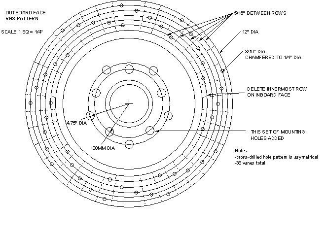
The first step was to figure out how the vanes were oriented between the inner and outer rotor faces since I didn’t want to drill into any of them. It turned out they ran radially outwards, not in a spiral like I had hoped. I prefer the look of spiraled holes as opposed to the one that run straight out from the center, but after pondering about it a little, I realized the vane orientation didn’t matter, so I created a little drawing and a template to guide me. (For those of you old enough to remember, I could probably have made use of my old Spirograph to create the template!)
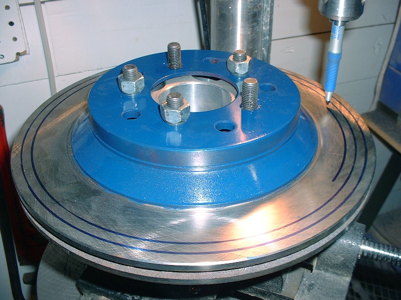
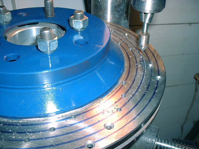
Then I set up the old bearing and spacer in the drill press. The bearing was useful since it turned the rotor into a handy-dandy turntable of sorts, while the 3" spacer kept the rotor from hitting the vise. Once my jig was lined up and leveled, I attached the rotor to the spacer with some lug nuts and was ready to start drawing out my concentric circles. I chucked a marker into the drill, set the correct radius up, lowered the drill just like needle on a vinyl record and spun the rotor. I made 5 concentric rings each 5/16” smaller in radius than the previous one by turning the adjuster cranks on the sliding vise.
Next I used my template to mark where the holes needed to go by lining up the vanes on the template with the vanes on the rotor. One of the benefits of drilling them in the pattern I chose is that the space between each vane only has one hole, except for some of the vanes with the inner and outer-most holes, which have two. By doing it this way, most adjacent holes are separated by a vane, creating an impediment for cracks to propagate from hole to hole. In the few spaces that have two holes, the largest possible distance (greatest material) separates the holes. With the hole locations marked, I started drilling 1/8” pilot holes.
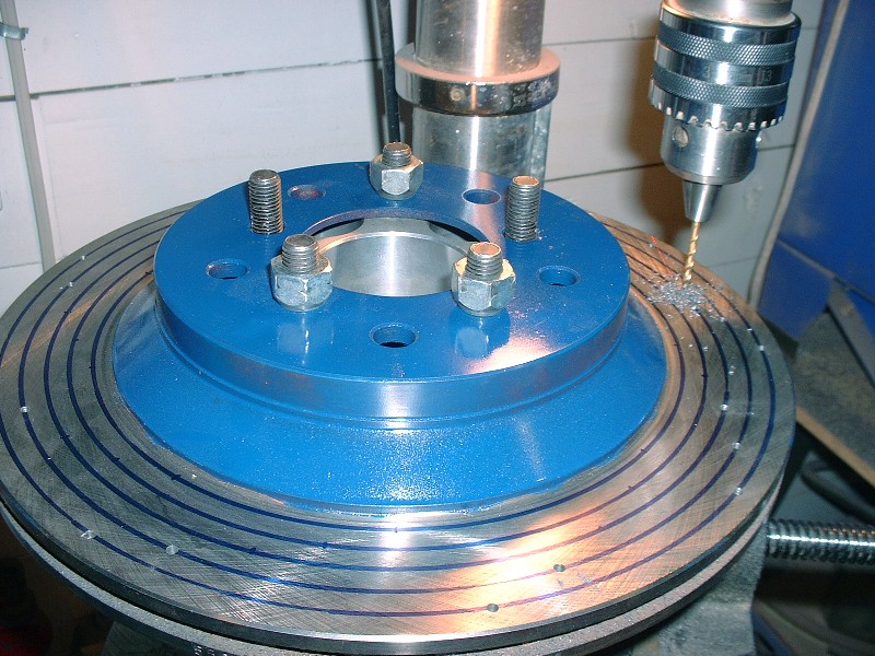
Then I stepped it up by drilling the final diameter. I chose 3/16” after researching typical cross drilled rotors on the internet. At first it seemed a little big, but I like it now.
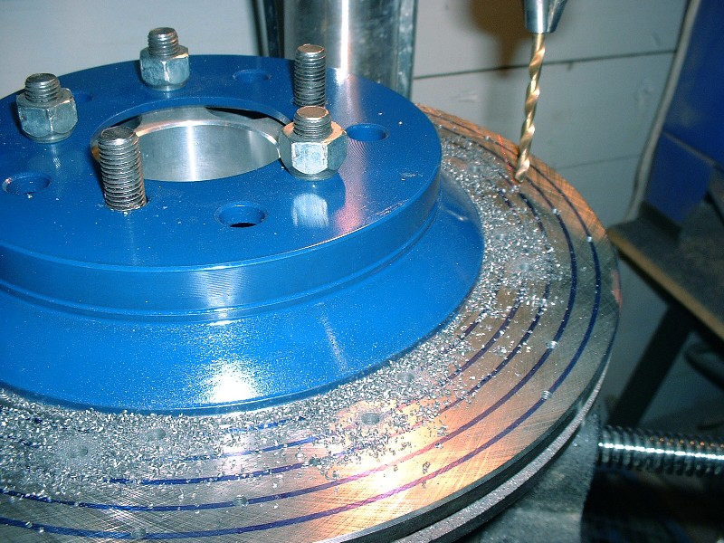
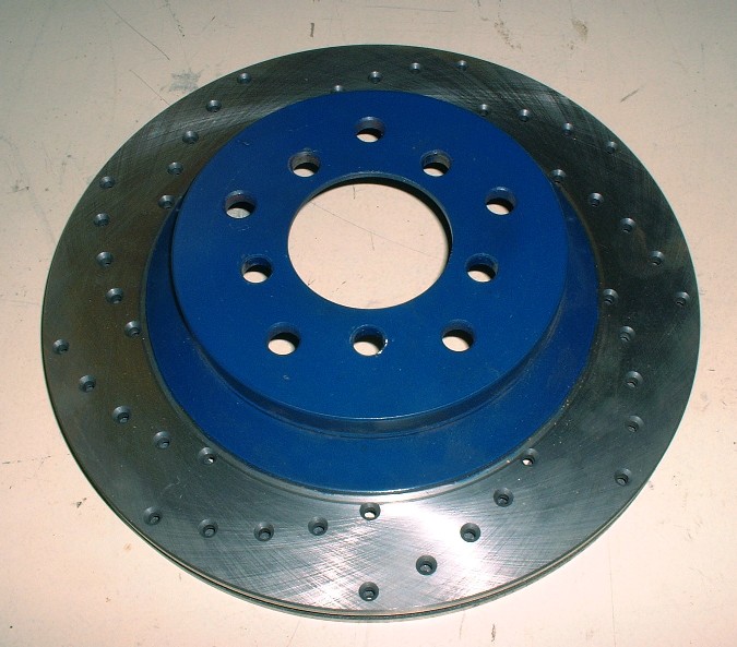
The final step was to chamfer all the holes to ¼” diameter, more for looks, but also de-burr them and provide greater stress relief. For the previous steps, I drilled right through both layers of the rotor each time, but for the chamfering, I had to do each side separately, obviously.
Here’s a completed rotor. I timed myself in case anyone else thought they might like to try doing this. It took me 2.5 hours to set up the jig and complete the first rotor, then each rotor after that took 1.5 hours. It makes for a long day at the drill press!
For comparison’s sake, I took a few photos of the Corvette rotor with the Grand Am/Beretta rotor (another popular upgrade). The stock Fiero rotors are 9.7”, the Grand Am’s are 10.25”, and of course the Corvette’s are 12”.
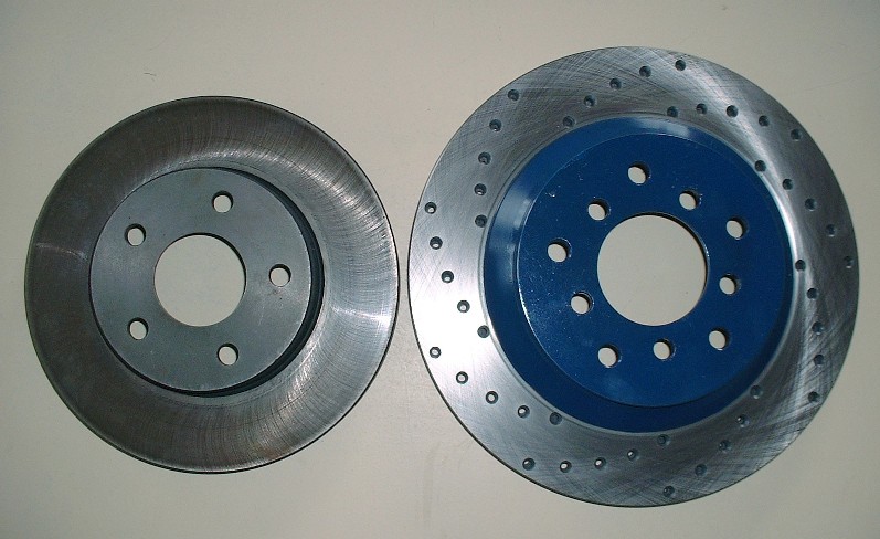
Another view of the GA vs Corvette rotor.
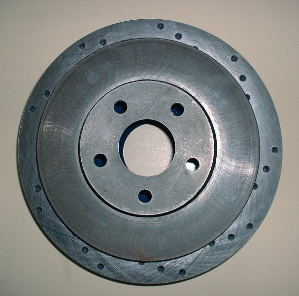
For the Corvette rotor to seat concentrically on the Fiero hub, most people know that you need an adapter ring to up-size the lip on the Fiero bearing flange. I got mine at the same time I got the caliper adapters from Fiero Addictions. To install them, it’s a simple matter of slipping it on to the snout and it’s done, but you have to be careful since there is a front and back side to the ring. The back side’s inside diameter is chamfered to accommodate the filet radius where the snout meets the flange.
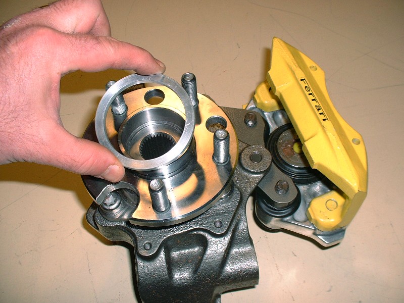
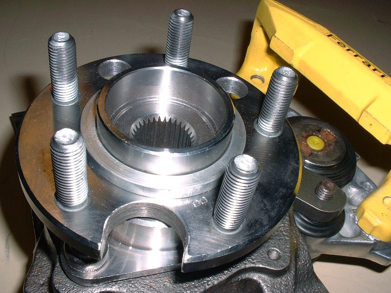
It should sit nice and snugly against the flange like this… if it doesn’t, then there’s a good chance you have the ring backwards or there some foreign debris between the two.
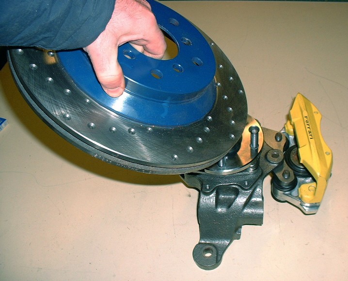
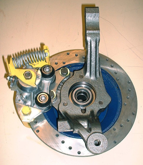
The last thing to do is slip the rotor on. I’ve found that it can be installed with the caliper already on the knuckle as long as the pads aren’t installed. You have to tip it at a bit of an angle though.
Then to secure it temporarily, I installed a couple lug nuts on a few wheel lugs. Here you can see how the hub centric ring takes up the space between the Fiero hub snout and the larger diameter center hole in the Corvette rotor.
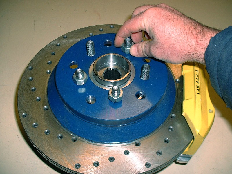
I still need to install the pads, roll springs, and the wire bales, but it’s starting to shape up.
I’m also progressing nicely on my F40 drawings and will soon start working on the N* drawings. I’d like to have them completed before starting the redesign of the cradle. That means I need to stretch out a few more suspension pics to buy time.
|
|
|
|
doublec4
|
JAN 29, 12:14 AM
|
|
Shaping up nicely!
Like many others have said, you pay amazing attention to detail, and have great patience when it comes to drilling/polishing/doing it right!
|
|
|
|
mattwa
|
JAN 29, 04:05 AM
|
|
|
Awesome! I do have a few questions if you don't mind that pertain to this. First, could I do this to my grand am brake rotors? And second, does cross drilling actually make a noticeable difference, what is the purpose of them exactly? [This message has been edited by mattwa (edited 01-29-2011).]
|
|
|
|
fieroguru
|
JAN 29, 08:05 AM
|
|
Looks good!
I would suggest checking the balance on the rotors once the holes are drilled. The inner portion between the vanes of the rotor is cast and not necessarily uniform thickness and with this variation you could have removed more or less material from hole to hole. Several of the Vette rotors I have used have some balance weights shoved into the vents to balance them and account for this casting variations within the vane sections.
|
|
|
|
Bloozberry
|
JAN 29, 08:17 AM
|
|
Thanks doublec4. Matt, you can do this to your GA rotors as well, just be aware that you should inspect the rotors more frequently for cracks that start emanating from the holes. Just Google "cross drilled rotor cracks" images to see what I mean. Some companies now offer dimpled rotors instead of drilling. The dimples are laid out in thte same neat patterns, but they won't initiate any crack sites.
The purpose for cross drilling is mostly cosmetic today, especially on road cars. With older brake pad compounds, the heat generated by braking caused the pad to release high pressure gasses between the rotor and the pad. Without a place to go, these gasses would literally force the pad away from the rotor causing less effective braking. Cross drilling relieved the pressure, but so did modern brake pad materials.
Edit: Good idea fieroguru... I should run them out to the machine shop and get them balanced. I'll post back here with the results.[This message has been edited by Bloozberry (edited 01-29-2011).]
|
|
|
|
dhobbs84sc
|
JAN 30, 01:11 AM
|
|
|
|
|