
 
     |
| Blooze Own: An F355 Six Speed N* Build Thread (Page 32/126) |

|
1fatcat
|
JAN 14, 10:01 AM
|
|
|
Blooze, your attention to detail is truely amazing! That is going to be one sweet ride! Keep up the great work!
|
|
|
|
Bloozberry
|
JAN 17, 07:09 PM
|
|
Thanks 1fatcat. I just noticed that the number of views is now over 15,000! I would never have guessed there would be this much interest.
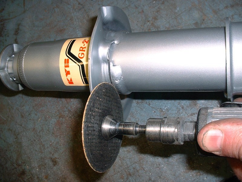
Anyways, with all the parts on hand to modify my new KYB’s into coilovers, I decided to convert them next. There are lots of threads on how to do this but I figured I’d document the process to buy more time drawing the tranny. Converting them was really quite easy. All it took was a die grinder with a cutoff wheel and a steady hand. The idea was to cut the old spring perch off the strut where it’s been welded on. I cut just above the weld and slowly went deeper until I could just see the underlying strut tube. It almost hurt to take the wheel to these brand new parts.
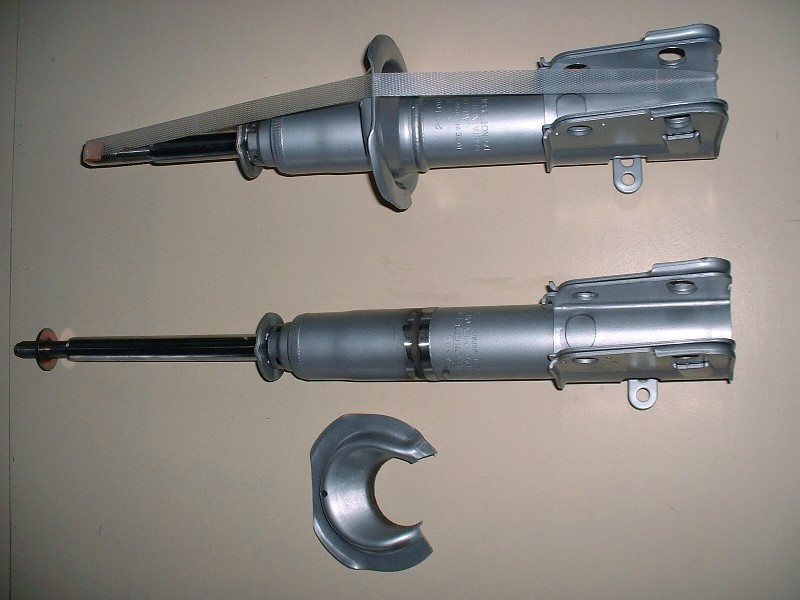
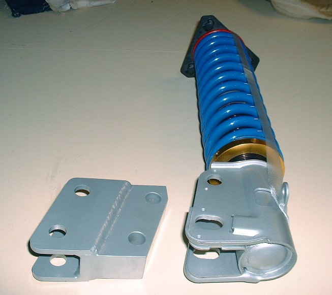
Once the spring perch was off, it was a simple matter of grinding the weld down flush with the tube body using the bench grinder. I found I had a lot more control doing it this way than with an angle grinder, which others have said they used. I also found that I had to get every last bit of weld off to be able to slide the threaded adjuster tube over top. Here’s the before and after picture of the two struts.
The next step is to slide the threaded adjuster tube over the strut body. It’s a tight fit. It comes to rest on the knuckle flange and would be OK just to leave it like that, but I used a bunch of silicone sealant between the two parts to keep moisture out and to keep the threaded tube from rattling against the strut body. It probably wouldn’t ever make noise given that the spring will always keep tension on it, but there was no harm doing this extra step.
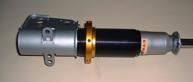
Once that was done, I slipped the springs onto the strut and seated them on the adjustable collar. I was somewhat wet behind the ears with respect to spring rates when it came time to order rear components. On the one hand, I didn’t want a rattle-my-amalgam-fillings-out-of-of-my-teeth ride like my 308 kit, but on the other, I’m planning for only about 4” of ground clearance so it can’t be soft either. Throw on top of that the added weight of the Northstar/F40 and the added leverage of the longer suspension links, I just didn’t feel like I had the ability to choose correctly. So I fed all of my particulars to HT Motorsports and had them recommend what they thought would be the best set up. This was at the time HT was being transferred to the new owner Erik, so I got the “benefit” of the old owner’s experience (Lee, I believe).
Lee suggested 350 in/lb springs in the rear and 325 in/lb in the front, despite my inner voice telling these are going to be way too stiff. He said that if I wasn’t happy with them, and as long as they were still in good condition, he would exchange them. I wonder how many years this offer is valid for… They’re 2.5” diameter X 12” (I believe) in the rear.
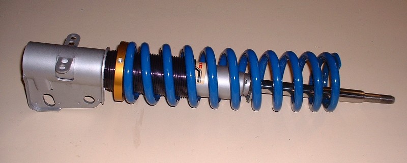
Enough about springs… to keep them in place at the top end, it’s a simple matter of sticking on a washer, a shaft bushing, followed up by a polyurethane spring seat, the hat, another shaft bushing, another washer, and the locknut. Tah-da! One adjustable coil-over:
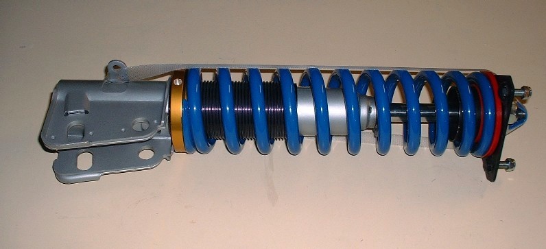
To finish off the assembly, all I needed to do was bolt on the lower strut adapters. They’re heavy suckers though so like I said, I’m going investigate shifting the upper mounts outboard instead of using these.
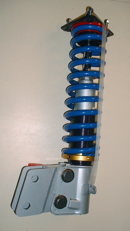
Here’s what they looked like after they were assembled. I used brand new M16 X 2.0 X 80 (10.9) bolts for them as well as for the ones that will attach the adapters to the tops of the knuckles. The old bolts just didn’t look right all pitted and rusty looking. At $2.50 each, they hardly even register on my cost spreadsheet.
Next up: big brakes… well, rotors anyway.
|
|
|
|
dhobbs84sc
|
JAN 17, 10:20 PM
|
|
| quote | Originally posted by Bloozberry:
Thanks 1fatcat. I just noticed that the number of views is now over 15,000! I would never have guessed there would be this much interest.
|
|
You deserve the recognition! Amazing job!
Umm.. I think your my dad? Can I come help  haha No but really good job! haha No but really good job!
|
|
|
|
doublec4
|
JAN 17, 11:09 PM
|
|
I have KYB's in the rear too, and I went with a 350 lbs-inch spring rate as well.
They're stiff, but not too bad. It's hard to tell how much stiffer it made it, considering I also added poly, and solid cradle mounts at the same time. However, the ride isn't too bad, and I never bottom out which is good news since you're going to have minimal ground clearance. Although you have more leverage on the rear suspension, I would think 350 is a safe bet. Not to mention, I remember reading that anything over 350 isn't recommended for the damping capabilities of the KYB. Otherwise, you might have to go to Koni's.
Looks great as always! Still watching this thread 
|
|
|
|
355Fiero
|
JAN 18, 03:53 AM
|
|
Blooz;
You will still need the lower extensions even after moving the rear shock tower mounts out. I went out as far as I could which essentially used the original outer shock mount holes as the new inner holes and made a new plate on top of the strut tower that stretched the outer mount bolt out. I found that the upper frame rail came into play when turning the strut around so you will still need some extension from the lower solid piece you don't like. I made my own but they are pretty much the same size or maybe a bit narrower but not much. You have a good 4" on each side of the Fiero to extend out with that body you have. It being the same as mine and all......
If you want pics of how I did my strut tower extension, drop me a line and I can send them to you.
Keep it up. It is going to look great when done.
Cheers
Don
|
|
|
|
Tony Kania
|
JAN 18, 12:17 PM
|
|
Dogcreek used 400 # springs on his LS4 build for about a week. The ride was entirely too stiff, and went down to 350 # springs afterward. It is still stiff, but not too much for our aging a$$e$. 
Keep up the great work. (We know you will!)
Tony
|
|
|
|
Icelander
|
JAN 19, 11:30 AM
|
|
|
I ran 250# springs on my '85 2M4 coil-over conversion. I like the ride. I also upgraded from the 13inch steelies to 17inch 45-series tires. The ride got quite a bit harsher after that change but I stick through the corners now much better than before. [This message has been edited by Icelander (edited 01-19-2011).]
|
|
|
|
Bloozberry
|
JAN 21, 08:47 PM
|
|
Thanks son (dhobbs), doublec4, Don, Tony, and Icelander for your input. If Tony says 350 lb spings aren't too stiff for his old creaky butt, then I guess I should be OK, but I hear you there doublec4 and Icelander... springs are only part of the equation. I'll be using polyurethane everything and much shorter tire sidewalls too so it all adds up. For Don, I get what you're saying about moving the tops of the springs too... there gets to be a point where the upper rail is the limiting factor... I hadn't thought that far into it yet. Looks like lower strut adapters might not have been a waste of money afterall! Yay?
OK, back to the thread-building. I lied in my last post. For this story to maintain some semblance of order, the next step has to be about building-up the knuckles. Unfortunately I didn’t take any photos of the knuckles before they underwent a cosmetic surgery, but I’m pretty sure most of you know what a 23 year-old rusty knuckle looks like. Here’s what my ’88 uprights looked like once they spent the day at the “spa” with an exfoliation treatment and some anti-aging "cream":
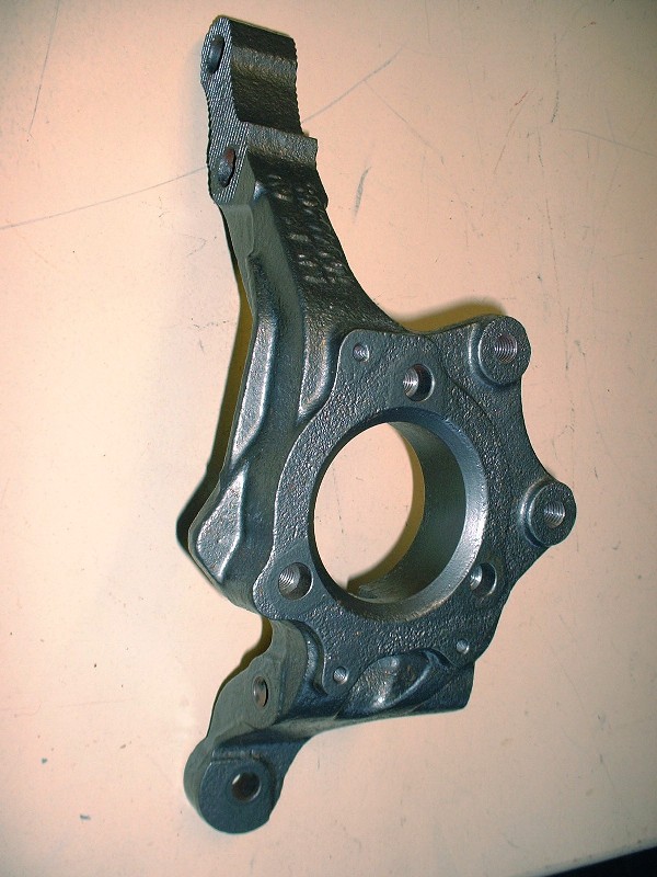
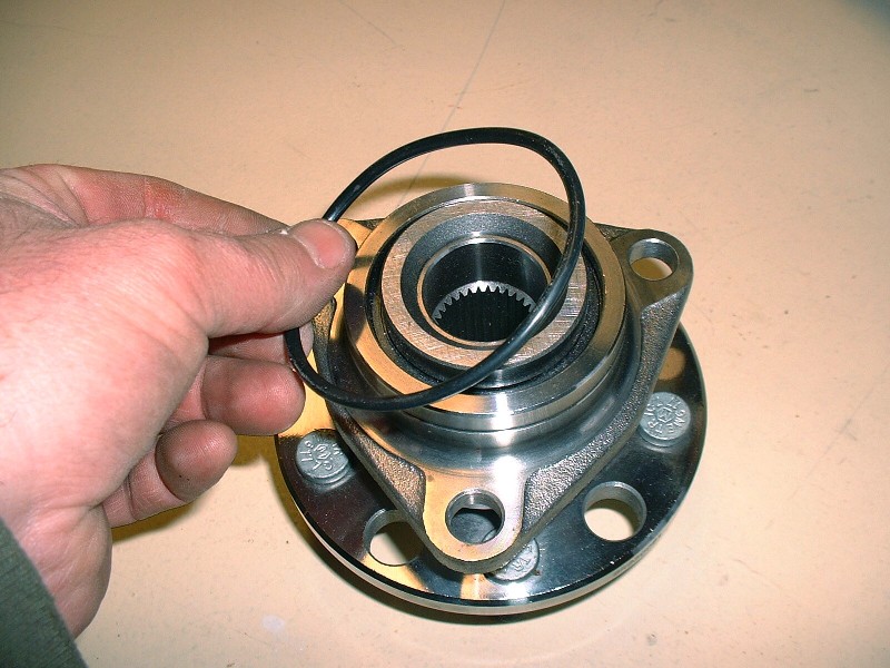
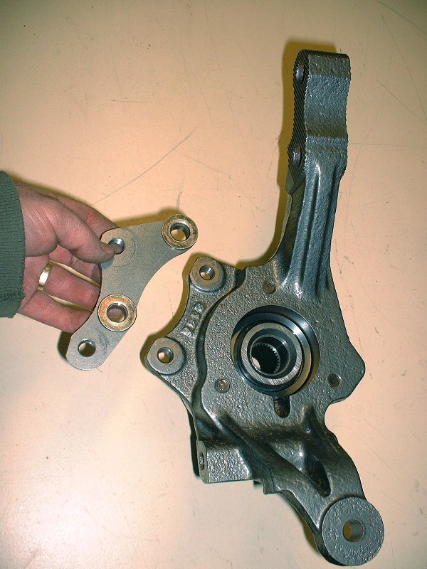
Because of the different rear suspension links, they’re considerably different than the pre-’88 rear knuckles. One thing GM kept the same on the rear though (luckily) were the wheel bearing assemblies. I bought new SKF units since the old ones had obvious axial and radial play in them. Nice shiny pieces. To help keep the road grime out of the inner bore of the knuckle, there’s a large O-ring that gets sandwiched between the bore and the bearing:
Then it’s a simple matter of placing the bearing on the knuckle and aligning the three retaining bolt holes;
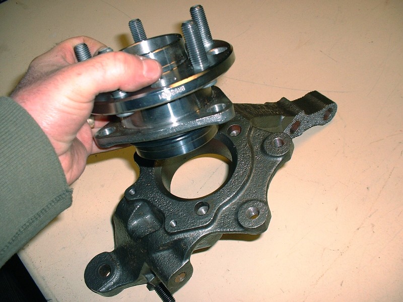
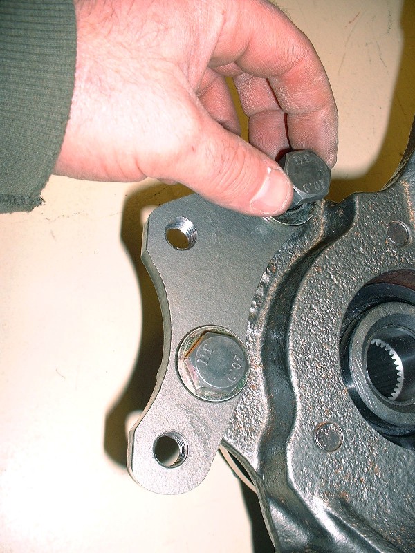
Installing the bearing isn’t rocket science, but since I had the camera out I took a few extra pictures in case someone has never done this before. The bolts that hold the bearing are M12 X 1.75 X 40 and are installed through the road-side of the assembly. Of course the wheel flange would get in the way if it weren't for a machined semi-circle allowing access to one bolt at a time:
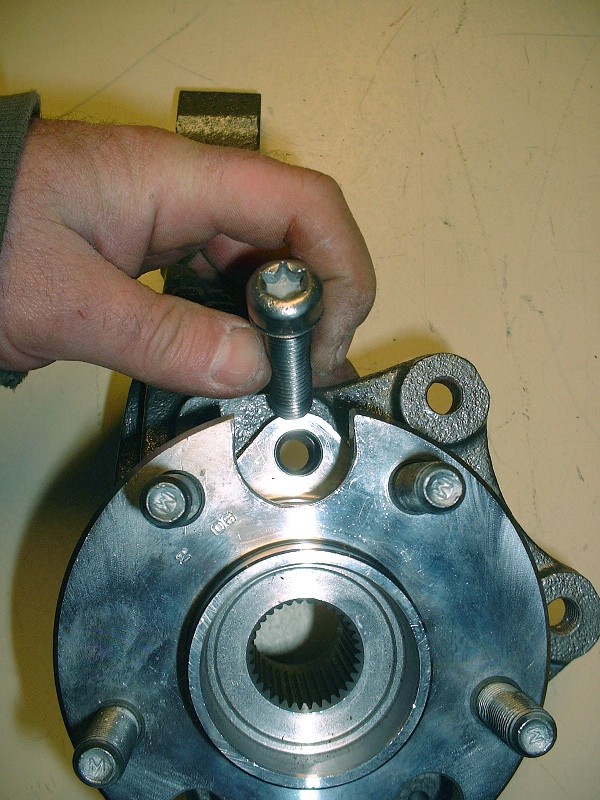
Once the first bolt has been snugged-up finger-tight, you have to rotate the flange on the bearing axis until one of other two holes line up, and repeat the process until they’re all finger tight. For the ‘88’s, the three bearing retaining bolts get torqued to 62 lbft.
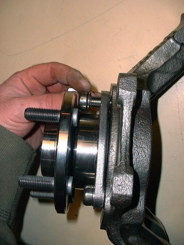
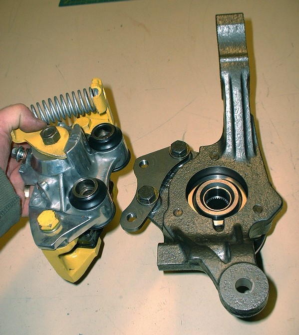
Next came the caliper adapters. I’m installing the ’88 – ’96 Corvette front 12” brake rotors on the back of my car, but plan to continue using the Fiero calipers for now. Lots of people have done this and it’s an inexpensive way to upgrade. That means though that the calipers have to be moved radially outwards (to accommodate the larger diameter rotors) AND offset slightly inboard to make up for the different offset in the Corvette rotor. That’s where the caliper adapters come in. I bought mine from the now defunct Fiero Addictions. Here’s a close up of one along with the hardware needed to bolt them to the knuckles:
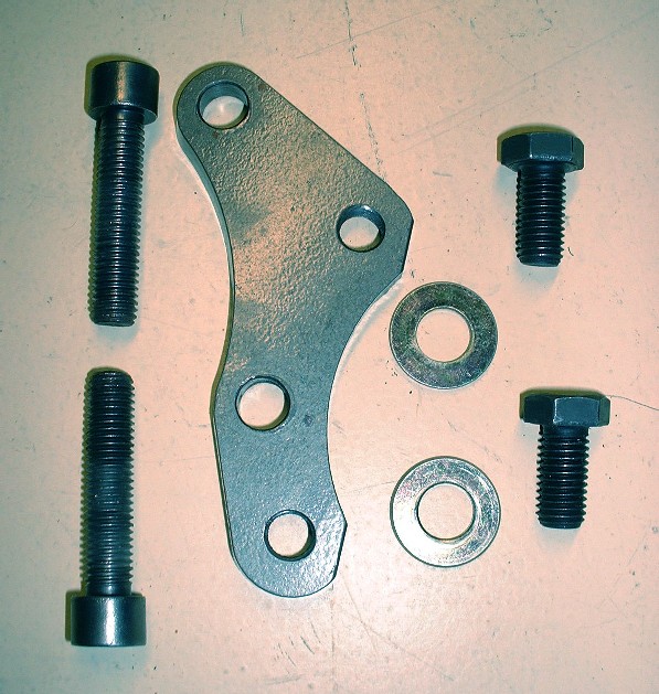
These adapters aren’t marked left or right, or top and bottom, which means you have to orient them so that the caliper ends up being installed a little lower than the OEM location. If the adapters are reversed, the calipers would end up higher up on the knuckle and would interfere with the strut mount.
The reason the calipers are rotated with respect to their stock position is so that they clear the heads of the bolts that attach the adapter to the knuckle. I’ll edit this post and add the bolt specs later, but they get torqued to 74 lbft. Other designs for these adapters have now come out that get around rotating the caliper by using countersunk mounting bolts. I’m sure it’s a good design too, but anyone who’s ever tried to loosen countersunk bolts after years of road use will realize the shortcomings of this idea. The very large contact area under the countersunk bolt heads makes it very hard to loosen them without rounding off the small Allen-key type recesses used to turn them. I've always had bad luck and ended up drilling most of these type of fasteners out after lots of frustration, so I try to avoid them now.
Now the brakes are next. [This message has been edited by Bloozberry (edited 01-21-2011).]
|
|
|
|
Bloozberry
|
JAN 24, 08:26 PM
|
|
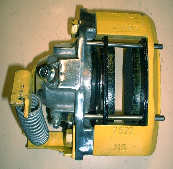
The brakes on the ’88 Fieros are different than for all the other years as pretty much everybody reading this knows. The overall diameter stayed the same at 9.7”, but GM finally upgraded the rotors to vented from solid discs. With this upgrade, new calipers were also needed to span the thicker rotor. The new calipers consist of two halves bolted together: one half is cast iron the other is cast aluminum. As mentioned earlier, my new brakes are going to consist of the stock ’88 single piston calipers for now, and vented 12” Corvette rotors. Theoretically, brake performance should improve since the calipers will be acting on the rotors with greater leverage. Practically speaking, I’ll have to wait and see how well it works out and upgrade to multi-piston calipers later if the performance isn’t up to snuff and if the budget allows it.
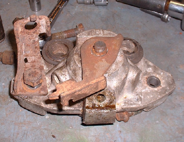
I didn’t get a good “before” picture of the entire ’88 caliper, so your imagination will need to be put to use again. I did however manage to save a picture of the aluminum half of one of them. Here it is in all its decrepitness:
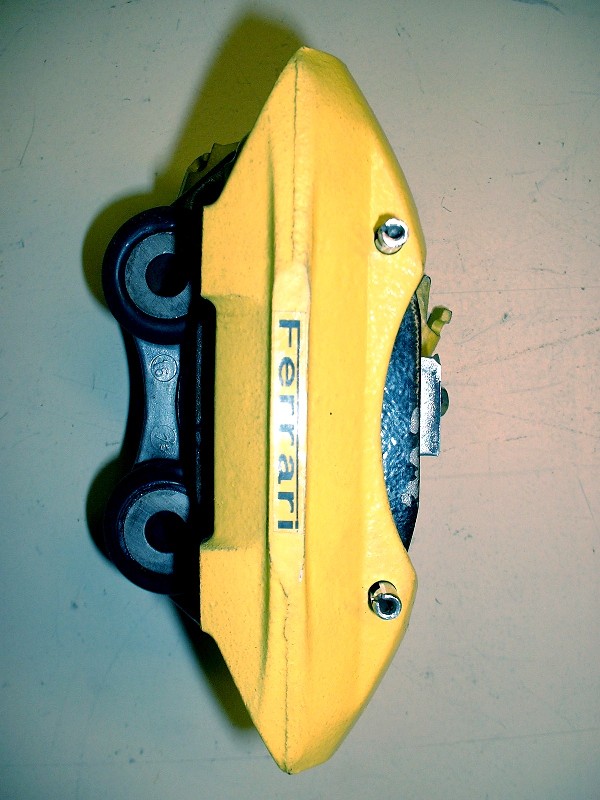
I bought a couple of caliper rebuild kits, new rubber slider boots from TFS, sandblasted, primed, and painted the cast iron halves, and cleaned up and polished potions of the aluminum caliper halves. When it was all said and done, they came out looking a lot better than they started:
Some of you may frown upon the Ferrari sticker, but I’m not going to spend any time defending them, so don’t waste any bandwidth criticizing. I made them with a sticky-label-making machine and have used them on my 308 kit with great success. They stick like bubblegum to a running shoe on a 112* day… and even better when it’s cold.
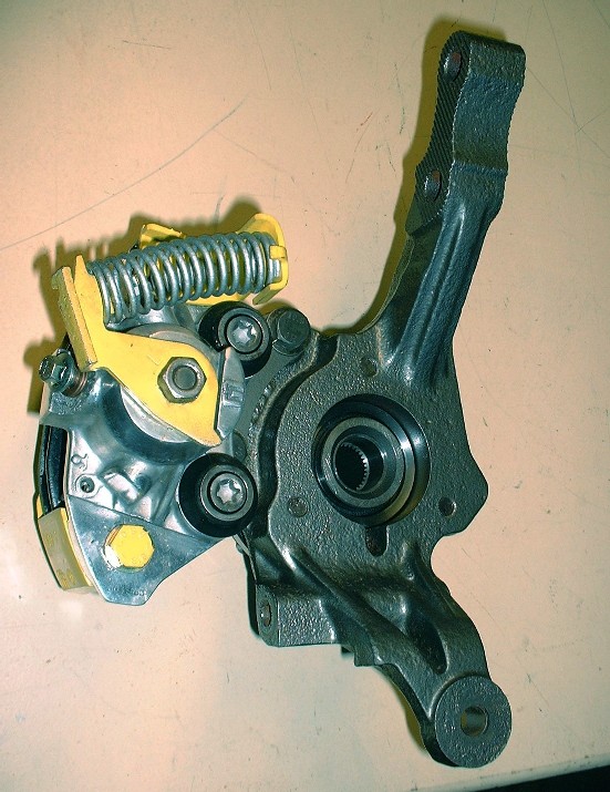
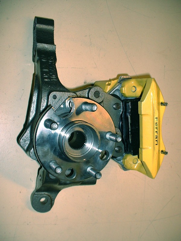
With the calipers completed, the next step was to install them on the adapter plates. You need a T55 Torx bit and a torque wrench set to 74 lbft to tighten them:
Here’s how puuuurdy they look once they’ve been attached for good.
And here’s the street side... I find they almost look like four piston calipers... if you squint.
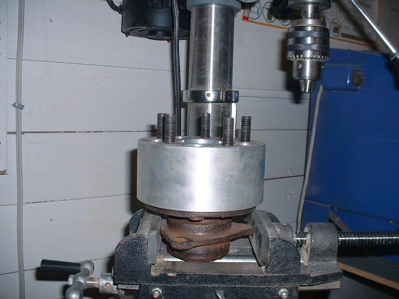
For the rotors, I got lucky when I went to the annual customer appreciation day at the local auto parts supplier. One of the many door prizes included four rotors of your choice… and luckily I happened to know of a car that needed exactly that. I think the owner was hoping that someone with a Geo Metro or a Hyundai Accent would win that prize. Now beggars can’t be choosers, so I did get the rotors but they weren’t exactly what the doctor prescribed. I only needed a little ingenuity and a bunch of time to make them just right. For starters, an old rear bearing assembly, an unused 3” wheel spacer and a drill press were the only bits of machinery I needed… any guesses what was wrong with my rotors?
|
|
|
|
cptsnoopy
|
JAN 24, 10:49 PM
|
|
Ummmm, needed to have the Fiero bolt pattern drilled?
Charlie
|
|
|
|