
 
     |
| Blooze Own: An F355 Six Speed N* Build Thread (Page 31/126) |

|
motoracer838
|
JAN 01, 12:46 AM
|
|
Blooze, that cradle is painful to look at. I just hate it when a project takes a turn like that. Seeing what you've done so far, I think I can guess what you might do about the cradle, but I'll let you suprise us.
Joe[This message has been edited by motoracer838 (edited 01-01-2011).]
|
|

|
Rickady88GT
|
JAN 01, 03:55 AM
|
|
|
|
|
Bloozberry
|
JAN 01, 10:30 PM
|
|
Erik, the car was from Ottawa Ontario, lots of salt used on the roads there. Rick, luckily the rest of the car seems really good. There’s a few little spots that’ll need a little attention, but nothing more than some stripping, priming and painting.
Charlie, Motoracer is on the right track. I won’t be needing another ’88 cradle… at least I hope I won’t!
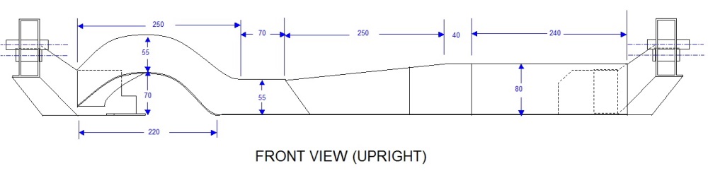
So I’ve been quite busy over the last couple weeks chipping away at some drawings of the ’88 cradle. I figured that before I cut out the front cross member, I should have some decent measurements of the whole thing. I was aware of the cradle drawing in the service manual, but if you’ve ever had a close look at it, there’s really not a lot of information contained on it, only the relative positions of the various mounting holes to one another, but not to any other part of the frame. My initial scope was to plot only enough information to assist me in designing a new cradle, but of course that turned into measurements of just about everything.
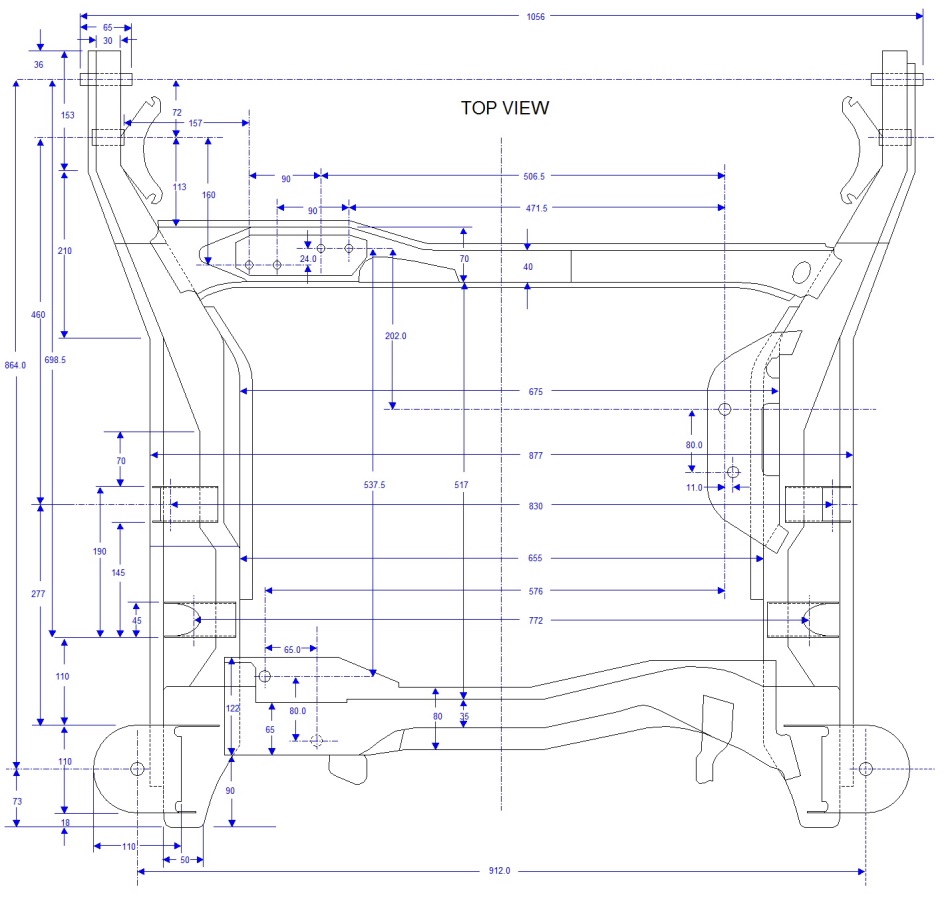
So for what it’s worth, here are the fruits of my labor, to be copied at will, I only ask that if you use them, to give credit where it’s due. I can email anyone with larger and greater resolution versions if so desired. Understand that in order to post them, I had to chop up the much larger diagram into it’s different views, so in many cases, if you’re looking for a measurement that isn’t in one view, it will be in another.
Here’s the front view of the cradle:
The top view:
The RH side view (which is nearly identical to the LH side view, so I didn’t bother drawing it out):

And the rear view:

With this work done, I was ready to start mocking up my spare Northstar to the old cradle to get some engine-to-tranny-to-cradle reference measurements.[This message has been edited by Bloozberry (edited 04-01-2014).]
|
|
|
|
fieroguru
|
JAN 02, 12:05 AM
|
|
Those are some pretty detailed drawings... I just imported the PDF of the service manual dwg into AutoCAD, scaled it to some known dimensions, and then outlined it... but then found out that the service manual drawing isn't square.
I would love a copy to add to my drawings. Please email it to fieroguru@lycos.com
Once you start building a new cradle, I recommend you lower the bottom of the cradle about 1" and push the side rails further out (not as much material inboard of the lateral links) to gain more clearance for the F40. Doing so will allow you to mount the engine/tranny as low as possible without the cradle rail getting in the way or the oil pan sticking below the bottom of the cradle.
I guess since you are doing a 355 with a wider stance, you could just build the extra width into the cradle as well.[This message has been edited by fieroguru (edited 01-02-2011).]
|
|
|
|
Bloozberry
|
JAN 02, 01:48 PM
|
|
Fieroguru, these are all excellent ideas. I'm still in the brainstorming phase of what to incorporate into my new cradle. Moving the frame rails outboard was one of the top priorities to make more room for the powertrain. And although I've already bought Held's 6" track width control arms, I may still choose to move the control arm mounting points outboard another inch too. That will open up a larger variety of wheel options given the rather limited offsets available for some of the nicer wheels I've been eyeing. There's no point in using spacers if I can design them out of the equation!
I'm not sure I understand your rationale for lowering the bottom of the cradle though.
Another major consideration is raising the control arm mounting points since I will accomplish getting the wheels at the right height in the wells by a combination of adjustable coil-overs, and raising the strut tower mounts. With no other mods, this of course would angle my control arms upwards and alter the dynamic camber change. So raising the mounts should restore the stock geometry while raising the wheels into the wells. But then I want to research anti-squat, and a host of other issues too, so more grey-matter needs to be exercised.
BTW, I sent you and BMTFiero the source file for the cradle drawings via your email accounts.
|
|
|
|
fieroguru
|
JAN 02, 07:28 PM
|
|
Thanks for the drawings. When I get an afternoon or two, I might put them into AutoCad.
As for lowering the bottom of the cradle, this allows you to lower the drivetrain to lower the CG and give you more clearance to the decklid hinge boxes, but doing so puts the axles at an upward angle as they go to the wheels. In the end it is a matter of personal preference.
Raising the front mount for the lateral link will reduce squating and is farily easy to do. Raising the lateral links at the cradle with the F40 is going to be a challange... not much room to move them, unless you raise the entire drivetrain. Depending on where you place the axle centerline vs. the wheels a large bolt boss will be very close to the front lateral link mount.
I am looking forward to seeing what you come up with for a cradle!
|
|
|
|
BMTFIERO
|
JAN 02, 11:01 PM
|
|
Thanks Bloozberry,
I got the drawings you sent me I am going to try to convert them to CAD.
|
|
|
|
FieroWannaBe
|
JAN 07, 11:31 AM
|
|
|
I wanted to just ask if you have recorded the wall thickness of the cradle. Is it mostly uniform for its members?
|
|
|
|
Bloozberry
|
JAN 08, 11:04 AM
|
|
FieroWannaBe: I took measurements from several places on the cradle to determine the original thickness of the metal and I got anywhere between 0.090” to 0.100”. The rustiness probably had an impact on the variability in wall thickness, but this should give you a range to work from.
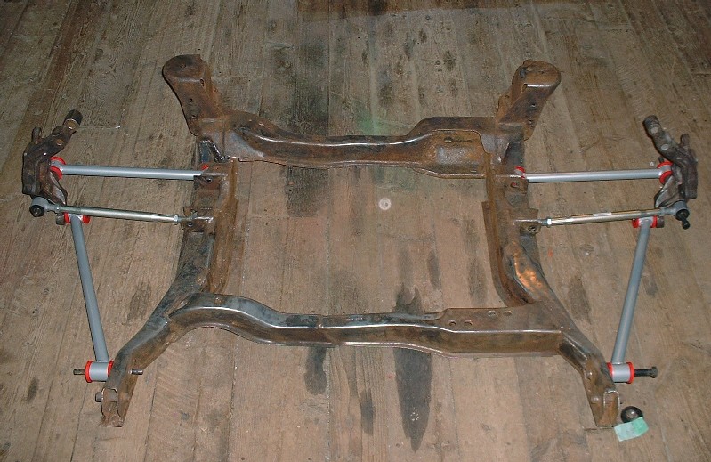
One last thing I did before cutting off the front cradle crossmember was to mock up the new Held’s rear tubular control links just to make sure they would align as promised. Here’s a sneak peak at what’s coming in the next post:
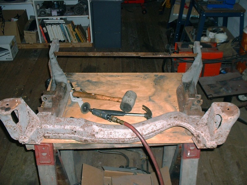
As most people reading this thread would know, the placement of the Northstar engine with the F40 transmission interferes with the OEM front crossmember, so the crossmember must be moved forward. I welded in a piece of angle iron between the two cradle side rails before doing any cutting to keep the rails properly positioned in relation to each other once the OEM front crossmember is removed.
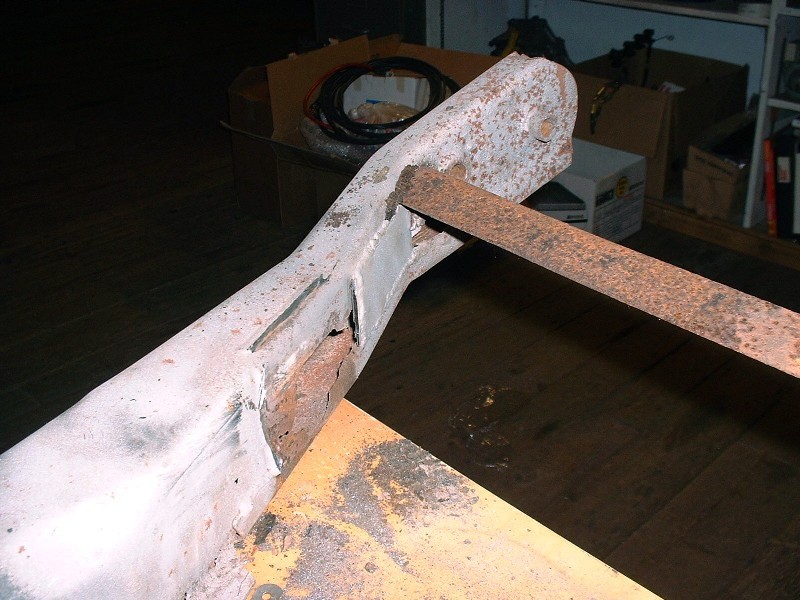
I used a cut-off wheel in my die grinder to cut through most of the welds holding the OEM crossmember to the side rails, although it was tricky to get the cutting wheel up the rear wall of the crossmember due to the angles. I found that the crossmember was under some stress because it sprang forward about a quarter inch once the final cut was made on the RH side.
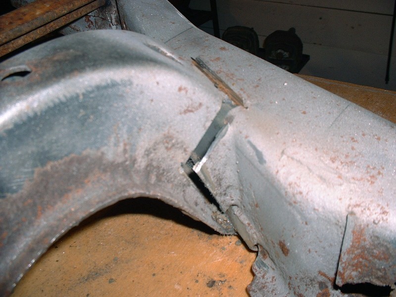
On the LH side, there was just no way to get the cutting wheel in the back corner so I resorted to using an open-ended hacksaw to get the rest of it. You have to be patient though because you can only get a couple inches on each stroke before the blade hits the inside opposite wall. This is where it would be nice to have an oxy-acetylene torch… and concrete instead of wooden floors!
With the final cut done, the crossmember just lifted out.
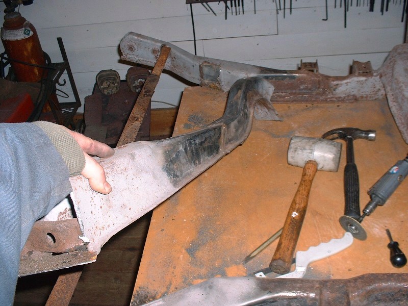
Here’s the offending piece. If only Pontiac would have had the forethought to install a Northstar-friendly cradle, things would have been a little easier! Surely the Northstar was on the drawing table at the time?
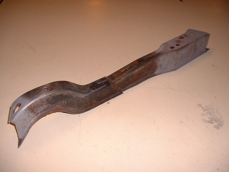
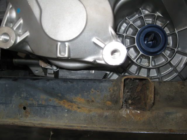
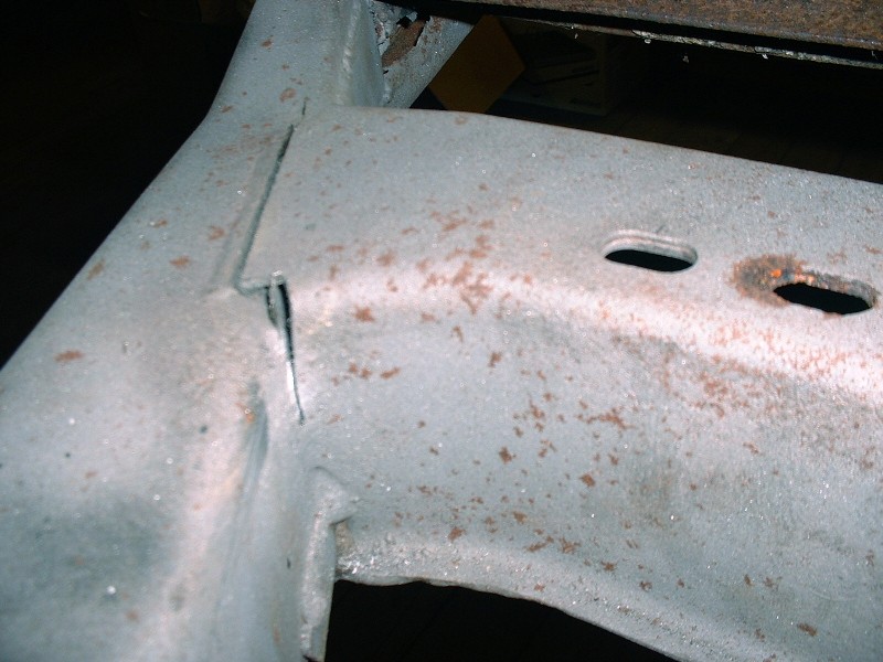
And looky-looky what have we here? More rust hiding in a critical area. Such a shame to have more iron ore than steel on an ’88 cradle.
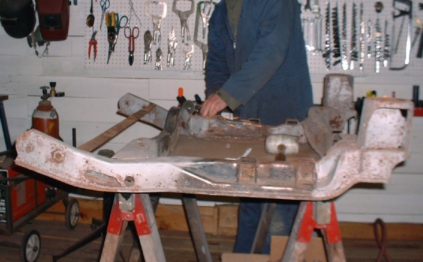
Here’s the overall view of the cradle without the OEM front crossmember. Again, the reason for me doing this even though I don't plan to use the cradle at all, is to be able to properly locate the engine and transmission assembly in relation the OEM cradle mounts, which dictate the location of the axles.
I’m using my spare engine for the mock up purposes so as not to accidentally damage my beauty queen. After setting the ugly sister on the bench, I had been hoping to be able to slip the cradle over top of it to get it in place… no such luck! So I needed the engine hoist again to make it right.

|
|
|
|
Bloozberry
|
JAN 12, 11:15 AM
|
|
So then, the next obvious step in the process would be to bolt the transmission to the back of the engine and start designing powertrain mounts. That would be great if the new cradle were going to be similar to the old one, but since I want to make a number of design changes (not all of which are clear in my own head yet), I need to spend more time at the drawing board. My goal is to have the old cradle, the F40, and the Northstar drawn out electronically so I can visualize the interrelationship between things like powertrain placement and planned suspension geometry changes. The electronic format will allow me to cut and paste at will, while minimizing time fabricating parts that don’t fit. Obviously it is going to be a time consuming process to draw multiple scale views of the transmission and engine, so I’ve saved some photos of the suspension upgrade process to keep the thread alive while I'm drawing.
For starters, here’s what the previous owner had in mind to get the wheels out three more inches per side to fill the wheel wells. Yep, three inch spacers:
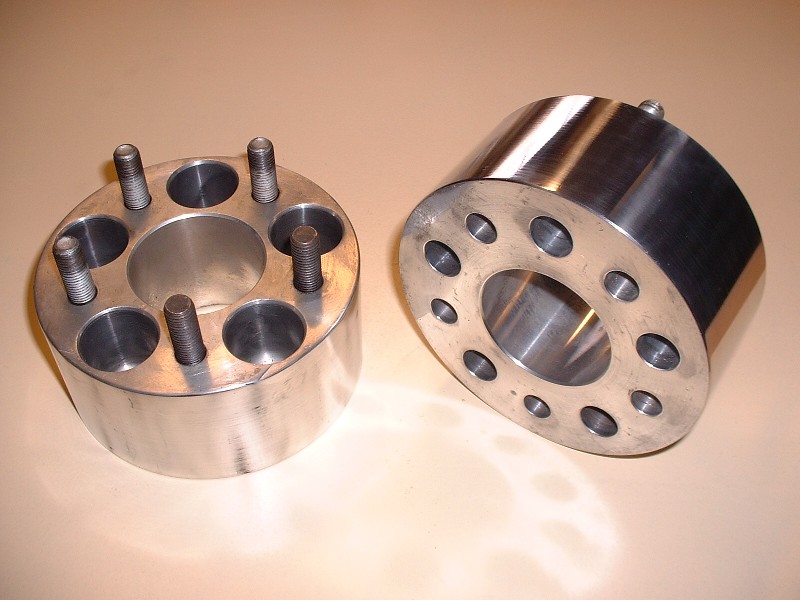
I don’t have anything against wheel spacers in the rear of a car where steering is not an issue, but moving a front wheel out by three inches makes the center of the tire contact patch walk around a 3” radius rather than pivoting on its center, among many other negative influences. Since I had the money to make it happen, I decided to spring for a better way to space out all the wheels. (BTW, anyone interested in a brand new set of four 3” polished aluminum spacers 5 X 100 on 5 X 100 for $50 each plus shipping, just PM me). This is the HT Motorsports (www.westshorefabricators.com/Fiero/index.htm) tubular rear suspension package, including do-it-yourself adjustable coil-overs, plus new KYB GR2 struts I bought locally. (The eagle-eyed among you will notice that I accidentally included a pair of front suspension parts in this photo too).
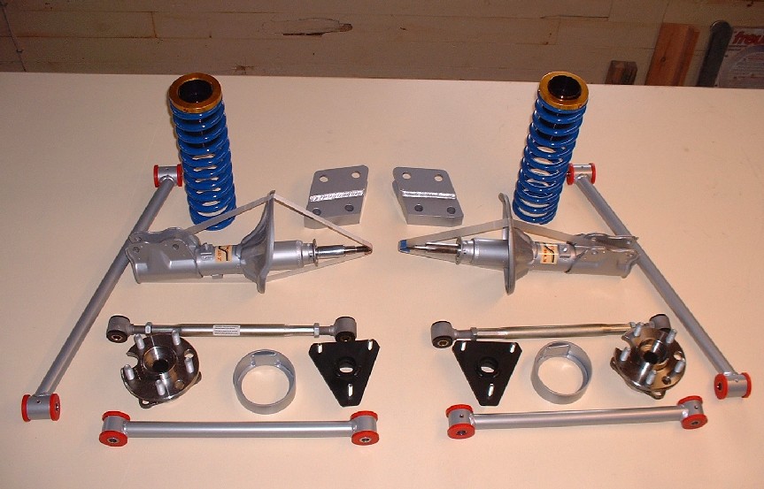
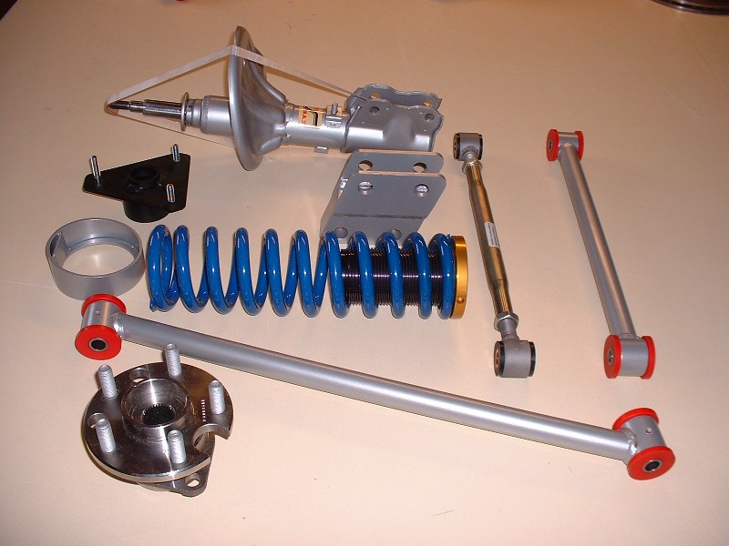
Here’s another view of the parts for one side. All kinds of nice new shiny parts! Eric at HT Motorsports will powder-coat your suspension pieces any color you like, although silver is not a common color, so at the time he didn’t keep any in stock. It took an extra week or so delivery-wise before he could fabricate the parts and have them done in my choice of color.
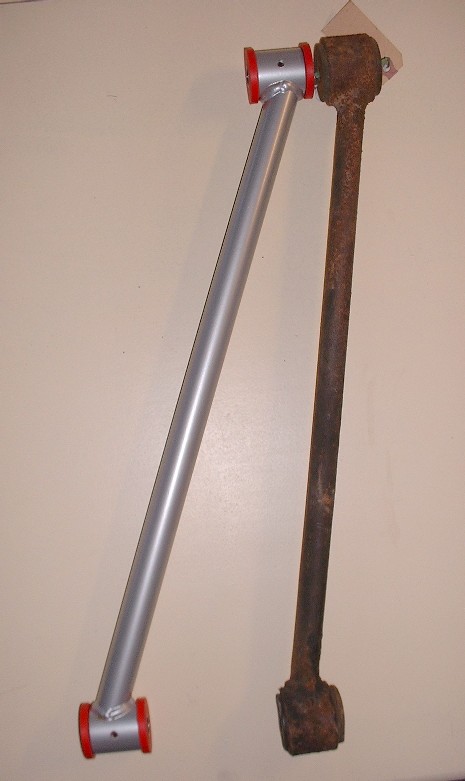
Here’s a few close-up shots of the parts. This is the trailing link compared to the OEM one. The link itself is only marginally longer, but the big difference is in the angle it must meet up with the knuckle:
Here are the lateral links for comparison. The nice part is that all the links came with polyurethane bushings, although recently I discovered that the inside diameter of the sleeves for the bushings had unacceptable variances (Thanks Rodney.)
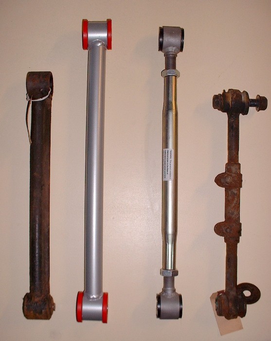
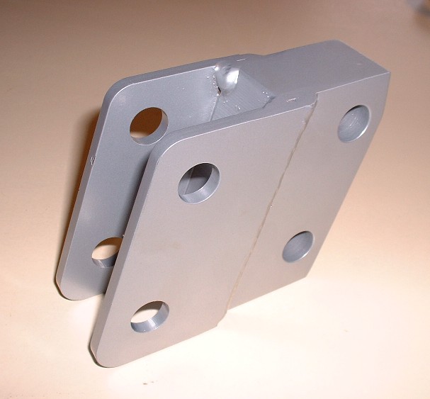
This piece is an interesting but unfortunate necessity. It’s a strut to knuckle spacer. By moving the knuckle outboard (which incorporates the lower strut mount) the angle of the strut would change significantly if nothing else were done since the strut upper mount is fixed. Two ways to remedy this is to either move the top strut mount outboard as well, or to use a lower strut mount adapter like this. The jury is still out regarding what I will do to solve this problem. I bought the parts, but now I am leaning more heavily towards changing the upper strut mounts for several reasons which I’ll get into later. One of the obvious ones though is to shed the needless unsprung weight of these adapters.
|
|
|
|