
 
     |
| Blooze Own: An F355 Six Speed N* Build Thread (Page 29/126) |

|
Erik
|
NOV 30, 05:00 PM
|
|
You're looking a little pale there La Forge ..time for a holodeck vacation 
|
|

|
litespd
|
DEC 13, 10:18 PM
|
|
|
Time for a bump to keep this on page 1.....
|
|
|
|
Bloozberry
|
DEC 17, 03:36 PM
|
|
Thanks for the bump litespd. I know it’s been a while since I posted an update, but I haven’t been sitting on my hands. I’ve been meticulously drawing out the stock ’88 cradle electronically for reference as I plan my own cradle design, plus Christmas shopping, filling out cards, and attending parties have gotten in the way, and most recently we had a 3 day power outage and property damage from 140 km/h (~90 MPH) windstorm. Wild weather!
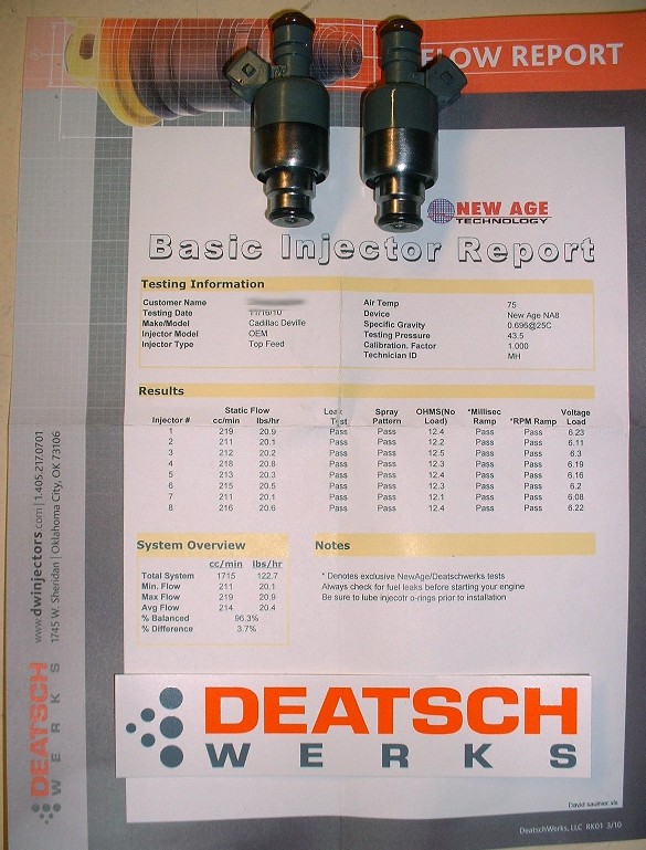
Anyways, I thought I’d take this chance to make a quick update on fuel injectors. Rather than replacing the OEM injectors with after market ones, I did some research and got some opinions here on PFF about cleaning them instead. There aren’t any shops in Canada that I could find that provide an uninstalled injector cleaning service, so I settled on sending them to an outfit in Oklahoma called Deatschwerks www.deatschwerks.com/catalog/injector_services.php Great company: fast turn around and a full report for $19 per injector. They disassemble, ultrasonically clean them, replace the internal filters, external o-rings, and test the coils, spray patterns, and compare flow rates. Not bad at all. Here’s my report card following cleaning. I can live with the 3.7% difference between the highest and lowest flowing injectors. Once I got them back, I masked the lower halves and painted them, of course, yellow!
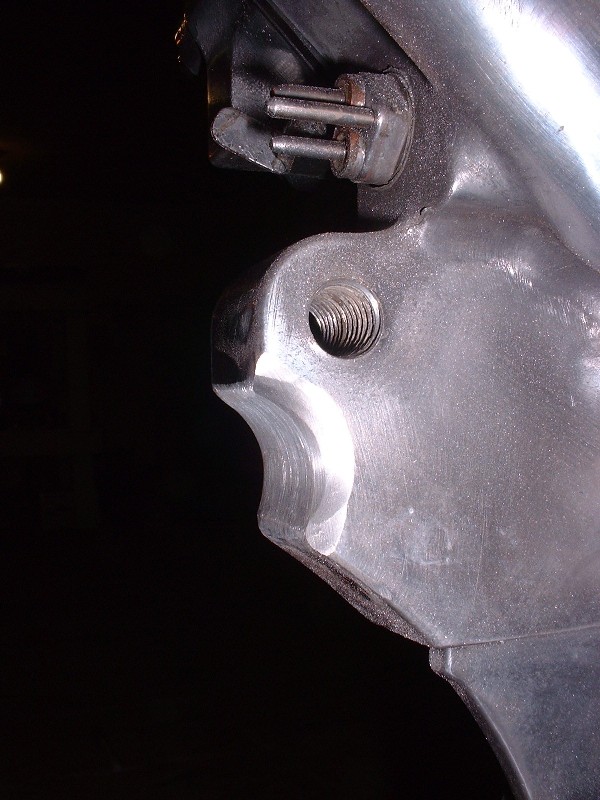
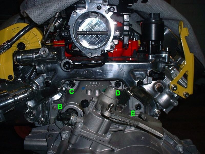
Now back to the transmission-to-engine mounting fun. Anybody who’s swapped a Northstar already knows the basic issues with mating one up with a standard GM Metric bellhousing pattern, but for those who aren’t familiar, this post is for you. For starters, here’s the rear view of the N*:
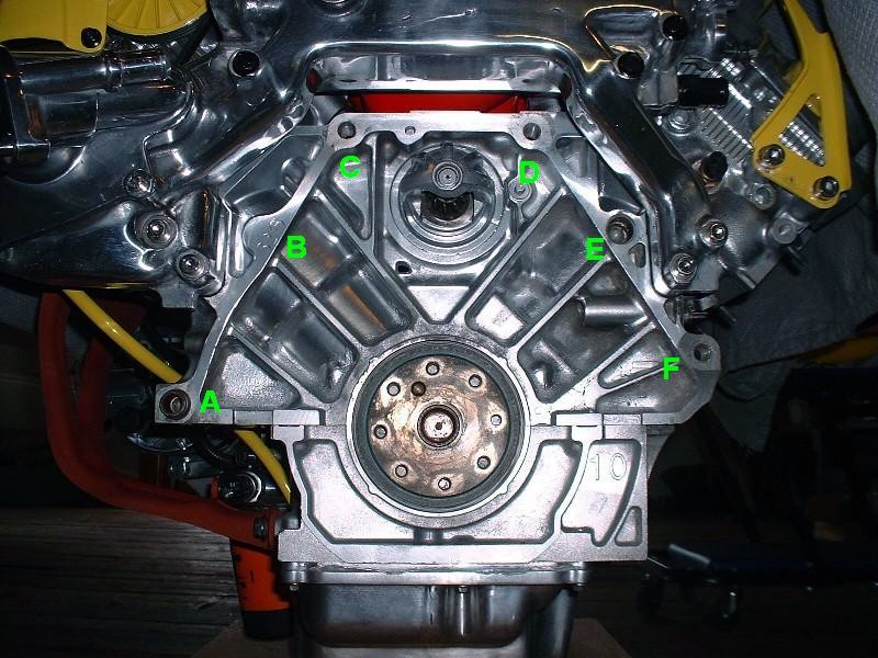
I’ve labeled the six locations for bellhousing bolts to illustrate which ones need massaging for the F40 transmission. The problematic holes are B, E, and F. Unfortunately there’s not much that can be done about mounting hole B. It’s not drilled or tapped on the N* for good reason. There simply isn’t enough depth of material between the bellhousing flange surface and the side wall of cylinder #8. It may be possible to safely drill and tap the location up to 3/8 of an inch deep, but then it wouldn’t serve much purpose, and it would more likely distort the cylinder wall or pull the threads out if any amount of torque were applied. Hole E is simply an unthreaded hole with an alignment dowel pressed into it, so it can’t be used as is to secure the transmission. The hole is waaaay larger than the M12 bolts used to mate the transmission to the engine. Finally, the problem with hole F is that the hole in the transmission bellhousing doesn’t line up with hole in the engine block.
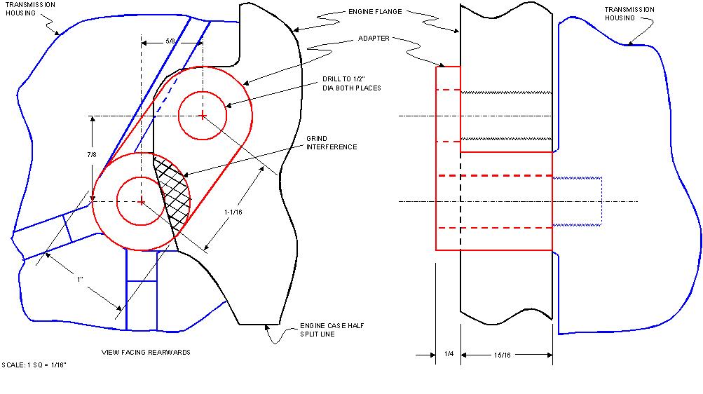
I started by addressing hole F. First, with the transmission mated to the engine, I drew out the dimensions of the two holes in relation to each other. This was an extra step I took so that anybody doing this in the future can design their own coupler with the key dimensions from the drawing. After some research, I decided to follow a similar (though not identical) design that PFF member “buds” used here, about 2/3 of the way down the first page www.fiero.nl/forum/Forum2/HTML/088691.html Note that regardless what design you use, there will be a need for some grinding on the engine flange since it covers a small arc of the actual bolt hole on the transmission.
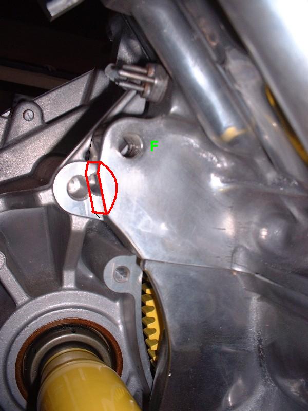
With my drawing in hand, I transferred the dimensions of the larger area I wanted to grind off the engine flange onto the flange itself. This is the view looking rearwards. (I traced the cut-out electronically onto the photo because there were too many reflections to see them properly in the photo.)
Then I used my handy grinding burr to remove the excess material. It ground down surprisingly easily, though I had to stop a few times to clean the bit to keep it from galling.

And here’s the finished product, although I had to make a few minor adjustments later on, which I’ll describe later.
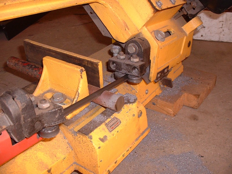
Next I needed to make my adapter. I started out by cutting a 1-3/16” length of 1” diameter steel rod. It goes amazingly fast with the right tools!
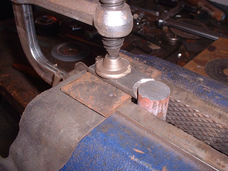
Then I fabricated the flat portion out of ¼” steel plate, drilled the 1” diameter arc using a hole saw, and finished by beveling the edges for good welding penetration. Here are the two pieces clamped in the vise ready to be fused into a single piece.
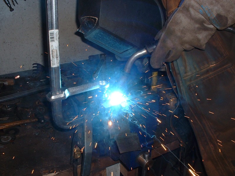
A quick zip-zap with the MIG welder on the inside and outside of the mating surfaces.
… and here’s the finished product once the welds were ground down smooth, and after a quick trip to the lathe to drill the 1/2" diameter hole through the center of the rod. The inside filet is the reason I needed to make a few adjustments to the engine flange notch. To make the adapter sit properly, I needed to grind a beveled edge on the flange.
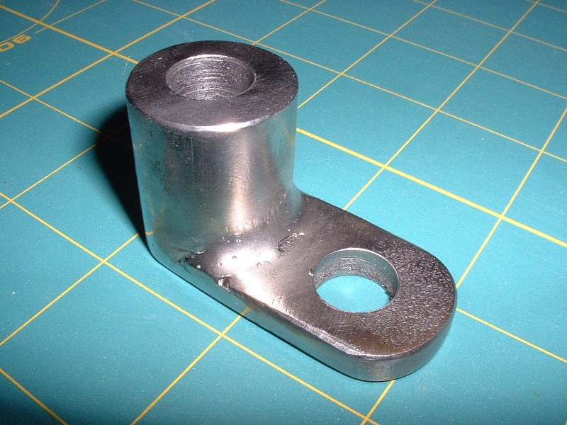
The moment of truth actually took a few test fittings since I found I hadn’t ground away enough aluminum from the flange even after beveling it. No biggie. To install the adapter, I used an M12 X 1.75 X 70 (12.9) in the lower hole, and an M12 X 1.75 X 35 (12.9) in the upper hole.

Edited to change bolt lengths used.[This message has been edited by Bloozberry (edited 02-21-2011).]
|
|
|
|
BMTFIERO
|
DEC 17, 04:50 PM
|
|
|
I want to thank you again for taking the time for starting and maintaining this thread you have really made my swap a lot easier.
|
|
|
|
Bloozberry
|
DEC 18, 01:30 PM
|
|
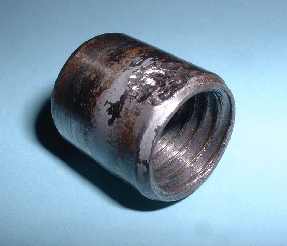
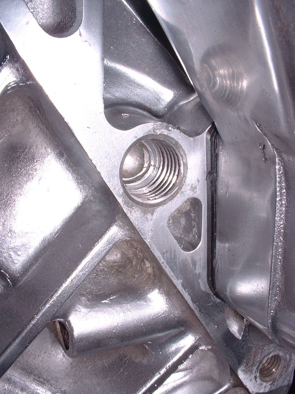
Next up was to figure something out for hole E. I did a bunch more research here on PFF but couldn't find anyone who had used this hole for a bellhousing bolt. Again, the problem with this hole is that there’s an alignment dowel pressed into it, but the inside diameter is not threaded at all. To make matters worse, the alignment dowel is pressed in very tightly making its removal very difficult. At first I tried the same method I used to remove the cylinder head dowels by shoving a steel rod down into the ID of the dowel to prevent the sides from collapsing as I tried clamping and turning the dowel with Visegrips. It wouldn’t budge and ended up galling up the sides of the dowel. I didn’t think of taking pictures at the time since I didn’t think removing a dowel would be worthy, but I took some afterwards given what I had to do to get it out.
After some measurements I found that the ID of the dowel was just about right to cut some 5/8” threads into it, and I happened to have the 5/8” X 11 tap handy from when I used Norm’s head bolt insert kit. So at first I thought I would just tap the OEM dowel ID, and up-size the bellhousing bolt to 5/8”. But then I realized that wouldn’t provide any clamping force because the dowel isn’t mechanically locked to the engine block except through an interference fit. But it did give me an idea on how to go about removing the dowel, so I tapped the ID anyways. Here it is mocked up with the tap after I actually got it out.
Then, using a spare insert from Norm’s headbolt insert kit (he sends you 21, but you only need 20), I threaded it into the dowel, and then threaded one of the used head bolts into the insert.
Finally, using a slide hammer under the head of the bolt, I was able to pull that sucker out of the block. What a PITA!
Now to make hole E useful, the idea was to fabricate a new alignment dowel that was threaded both on the outside diameter to lock it to the block, and on the inside diameter to allow a standard M12 x 1.75 bellhousing bolt to be used to bolt the tranny to the block. I drew out a schematic of what the new threaded alignment dowel should look like with the appropriate measurements so you don’t have to go through it all yourself:

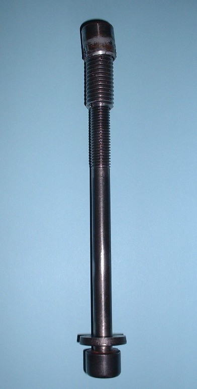
To make it, I bought an M20 X 2.0 X 60 bolt ($3) and had a friend with a machine shop remove the head, then machine the threads off one end along an 8 mm length to a new OD of 18.5 mm, which is equal to the OD of the OEM dowel. You’ll notice from the picture that it didn’t end up removing the entire depth of the threads, but that doesn’t matter. This will be the end that will stick out of the block. Then he drilled and tapped the core of the new dowel for the M12 X 1.75 bellhousing bolts, and finally cut it to the correct overall length.

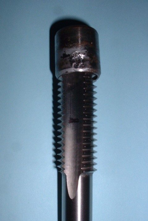
Next step was to tap the engine block where the old dowel was. The hole, as mentioned before, is 18.5mm in diameter, so that’s why I went with the 20mm bolt for the new dowel. I bought an M20 X 2.0 end tap ($36) and threaded the engine hole without any problems.

Just be careful if you do this not to over torque the tap as you reach the bottom since you risk stressing the cylinder wall.
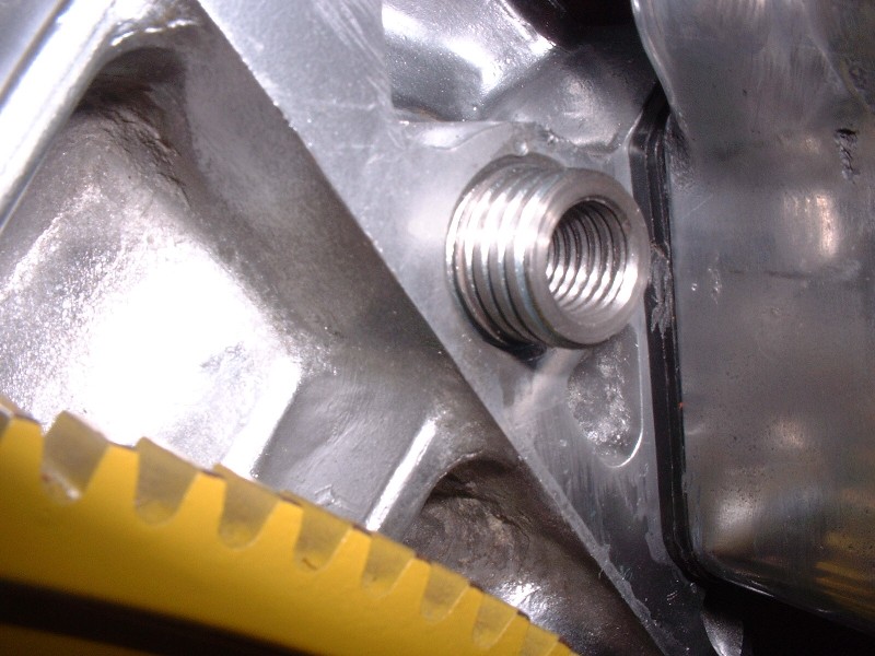
The rest was a walk in the park. I just screwed the new threaded alignment dowel into the block (I’ll use thread locker for the final installation later on).

Make sure that the OD threads of the dowel are completely recessed into the block and that the only part protruding is the part that the threads were shaved off:
And install the transmission.
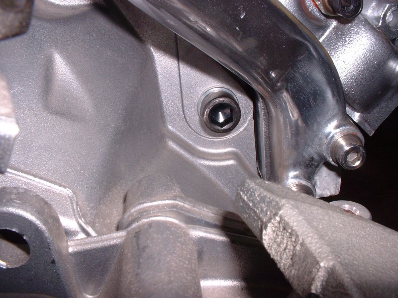
I used the following length M12 X 1.75 bolts in the locations identified in my last post: A = 50mm, B = nothing, C & D = 70mm, E = 30mm, F (top) = 35mm, F (bottom) = 70mm.
|
|
|
|
Amida
|
DEC 18, 08:15 PM
|
|
|
Wow! That looks so clean. Nice work.
|
|

|
fierogt28
|
DEC 18, 09:10 PM
|
|
Blooze, this is probably one of very few detailed engine swaps here I've ever seen on PFF. I love the fact that you describe / mention / show what is going into the project. Plus the cleanness and show quality that is going into it. I'm not a fan of yellow paint, but that's your taste and preference. The top intake that is painted "fire red" is an awesome color; very hot.
Not just putting a engine and tranny together is the issue here, its all in the detail and recommended torque values indicated. Not many folks respect doing that when doing assembly. You know what I mean, not just torquing the heads down and the rest isn't important.
You do quality job and in the end it pays off, big time !! Plus you got on hell of a nice swap ! :P
Have a good X-mas...
------------------
fierogt28
88 GT, Loaded, 5-speed.
88 GT, 5-speed. All original.
|
|
|
|
DeLorean00
|
DEC 18, 10:17 PM
|
|
Wow!! Your work is simply amazing.
What is your background if you don't mind sharing? Fabrication skills like this don't just come out of thin air. ------------------

|
|
|
|
Bloozberry
|
DEC 18, 10:47 PM
|
|
Thanks for the compliments Amida, fierogt28, and DeLorean00. I sometimes wonder whether I'm overdoing it with too much info and too many pictures of stuff that may be obvious.
| quote | Originally posted by DeLorean00:
What is your background if you don't mind sharing?
|
|
I'm an ex-military aircraft engineer. I retired six years ago as the senior aircraft maintenance officer at the headquarters level on Canadair Challengers, the Snowbirds aerobatic team aircraft (Tutors), and the now retired T-33's, and F-5's.
|
|
|
|
17Car
|
DEC 19, 12:17 AM
|
|
On the contrary, the more pictures the better. Have leaned so much from this thread already. 
Have you figured out how to wire up the alternator yet?
|
|
|
|