
 
     |
| Trinten's SBC/F23 build - The work has begun! (Page 28/76) |

|
Trinten
|
DEC 28, 10:34 PM
|
|
| quote | Originally posted by Blacktree:
Welcome to the Construction Zone. Cool build, by the way.  |
|
Thanks BlackTree,
FieroGuru has been great about sending me PMs with updates. And recently he had mentioned he was going to have some more stuff up in the thread. I realized that I hadn't gotten a notice of posts being made to the thread. So I found my old thread, and was shocked when I saw it said "Thread Closed" -- I was like "What happened?!" then saw the link about it being moved here!! lol
Everything looks incredible FieroGuru, thank you so much for all the attention to detail you've put into this.
I think the alternator I have on there puts out 230 Amps, will that cause problems with the 200 amps fusible link you installed?
Seriously pumped up about this![This message has been edited by Trinten (edited 12-28-2013).]
|
|
|
|
fieroguru
|
DEC 29, 03:20 PM
|
|
| quote | Originally posted by Trinten:
Everything looks incredible FieroGuru, thank you so much for all the attention to detail you've put into this.
I think the alternator I have on there puts out 230 Amps, will that cause problems with the 200 amps fusible link you installed?
Seriously pumped up about this!
|
|
Thanks!
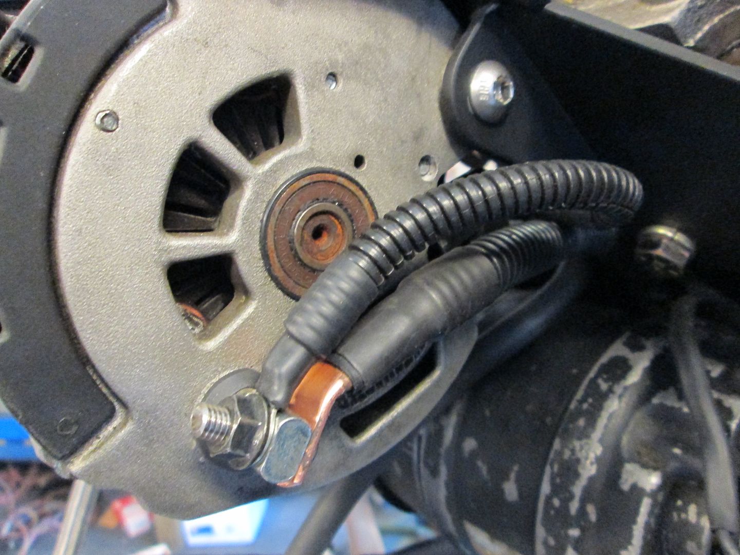
The alternator is part # 47802 and should be a 140 amp alternator, unless you had a local shop do the upgrade to 230 amp. Fully loaded LS4 cars come with a 135 amp alternator, so 140 should be fine for this swap.
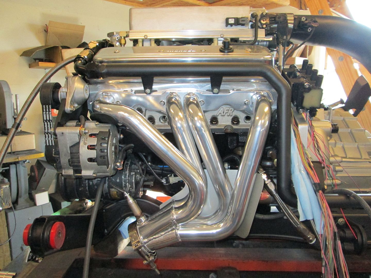
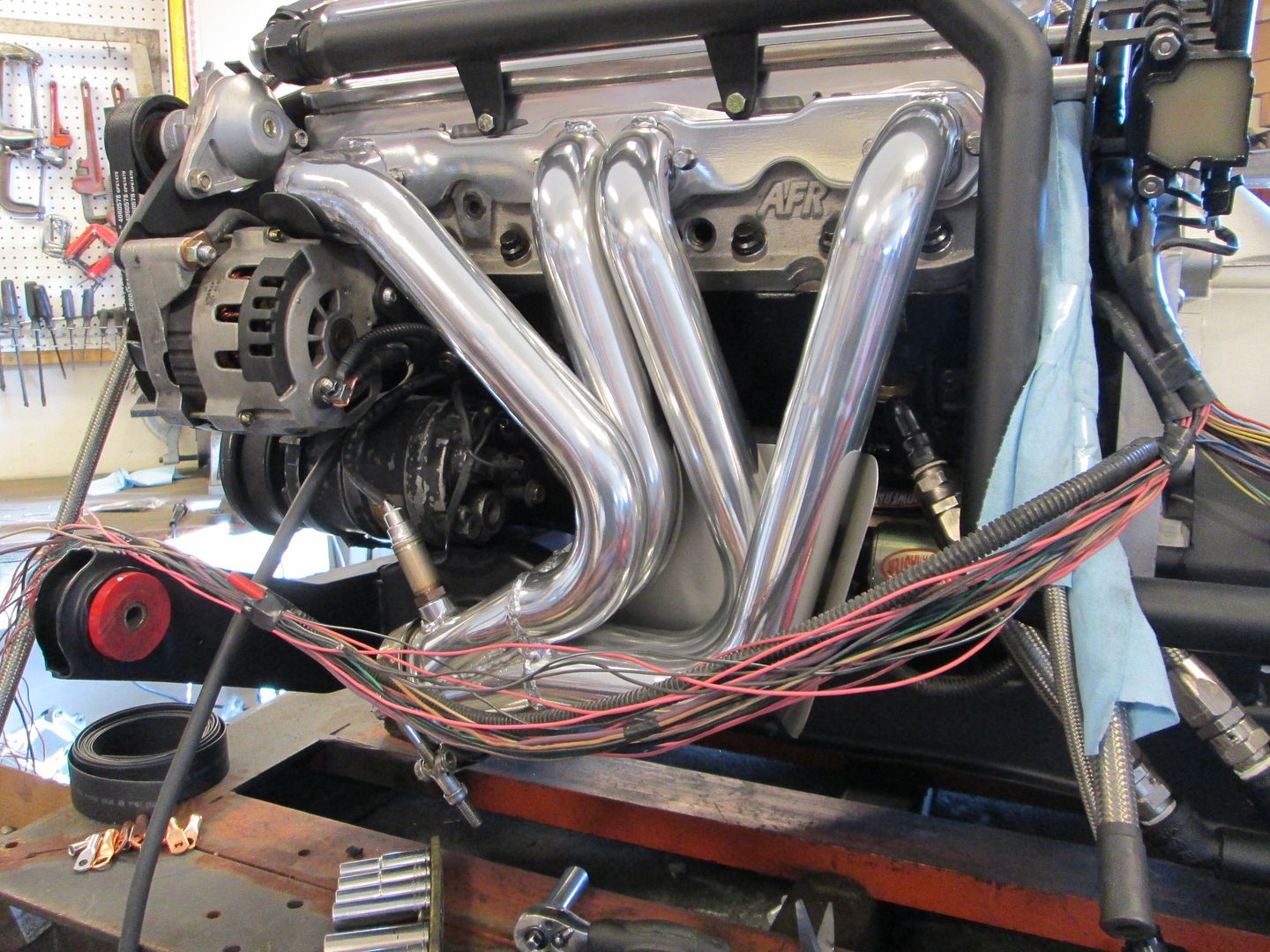
Put the oil filter housing back on:
Then the coolant crossover pipe and front header:
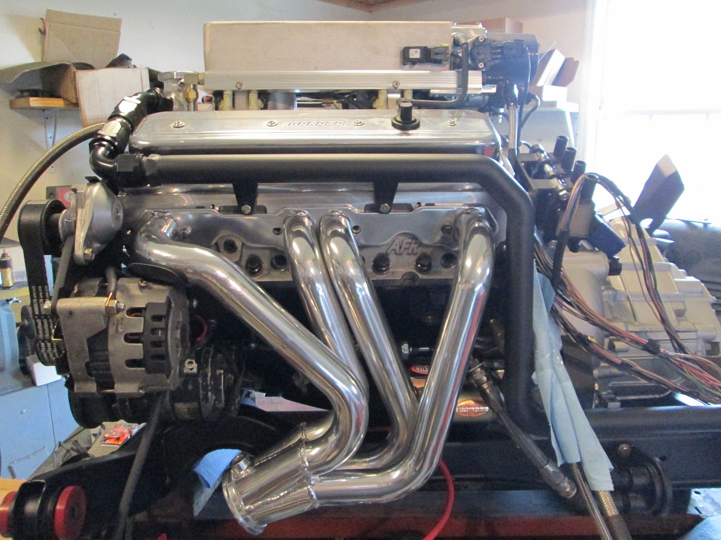
Also the 4" air intake tube to verify the MAF wires are long enough:
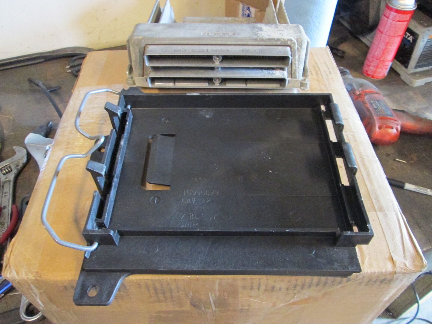
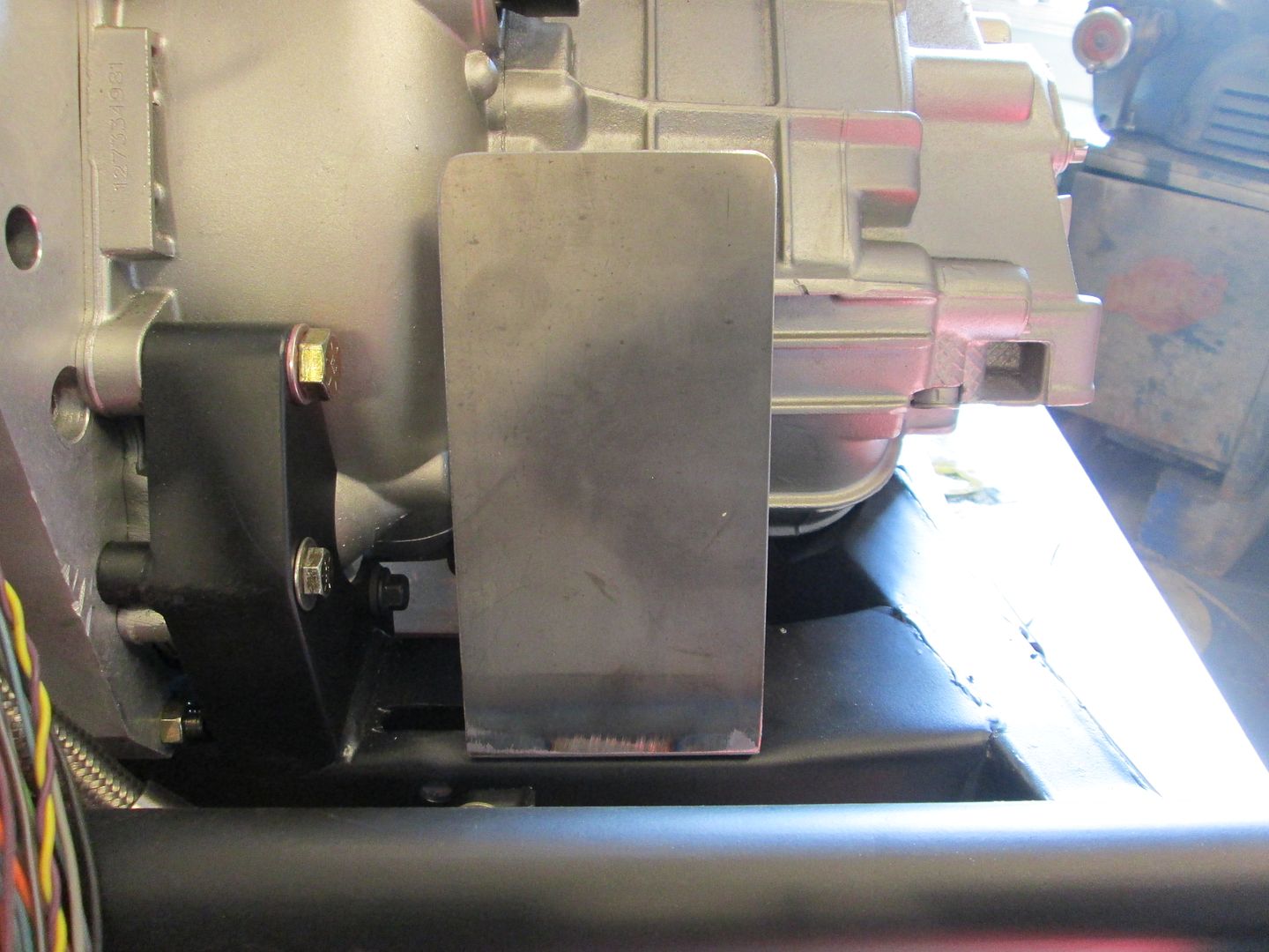
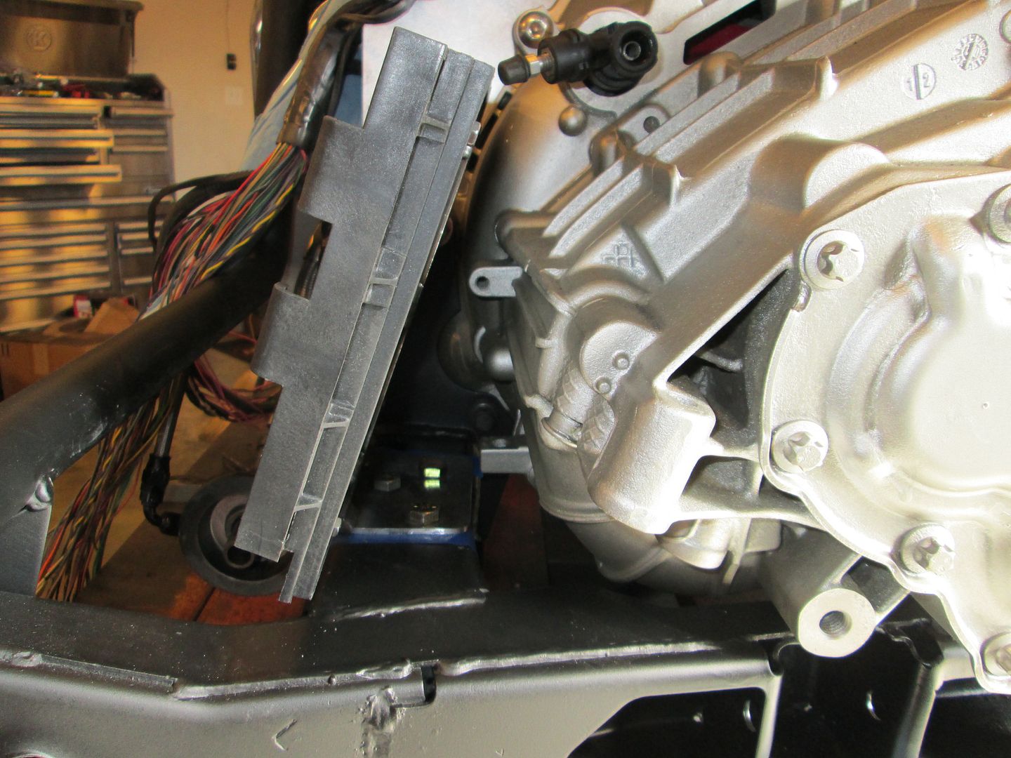
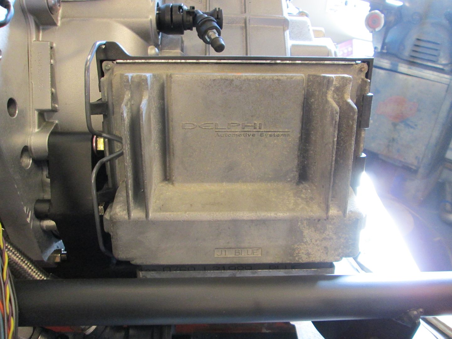
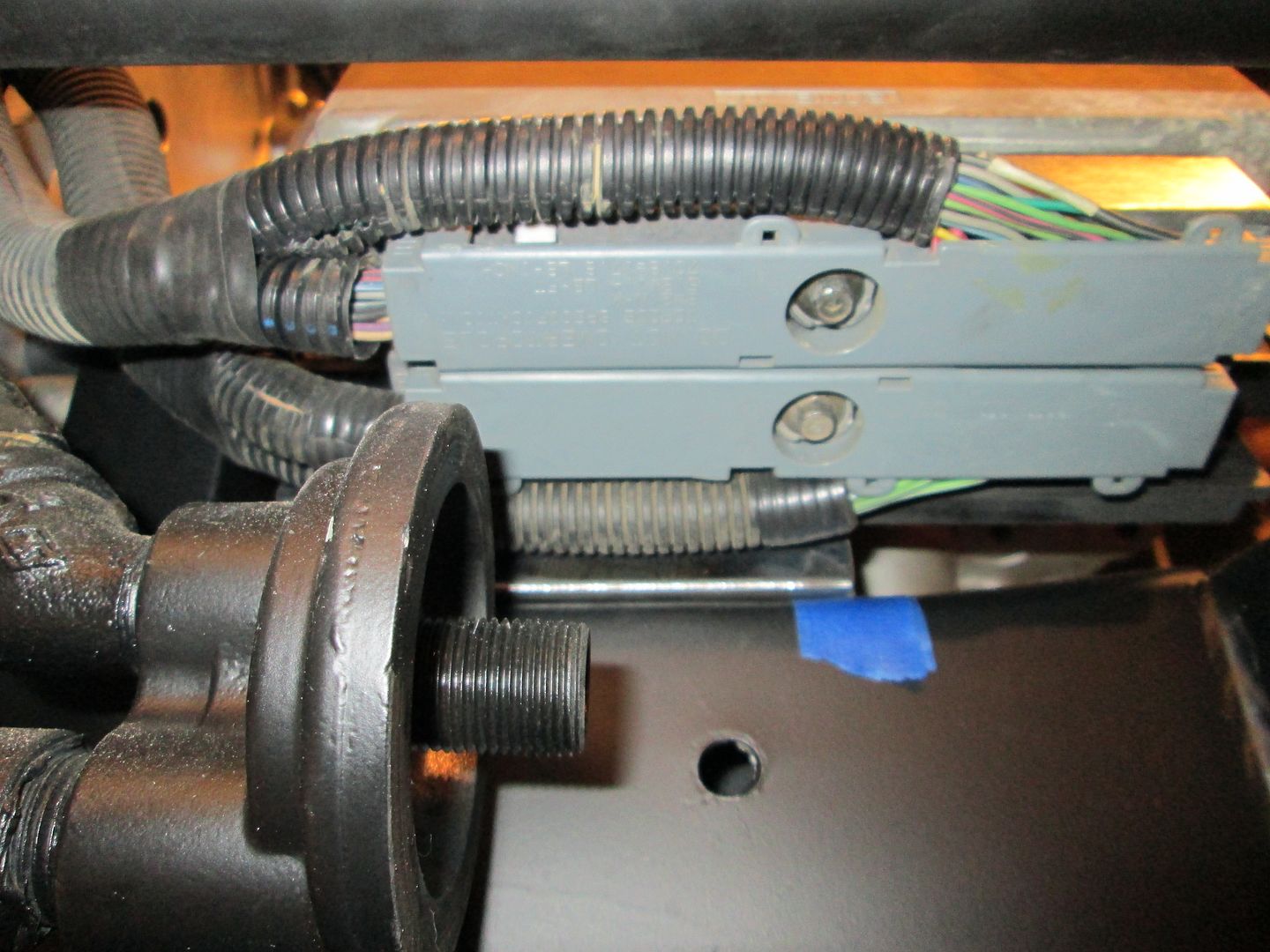
This looks like a good place for the ECM. It will be mostly hidden from view and away from any significant heat sources. Just need to make a support bracket that will attach to the cradle via the stock transmission mount holes:
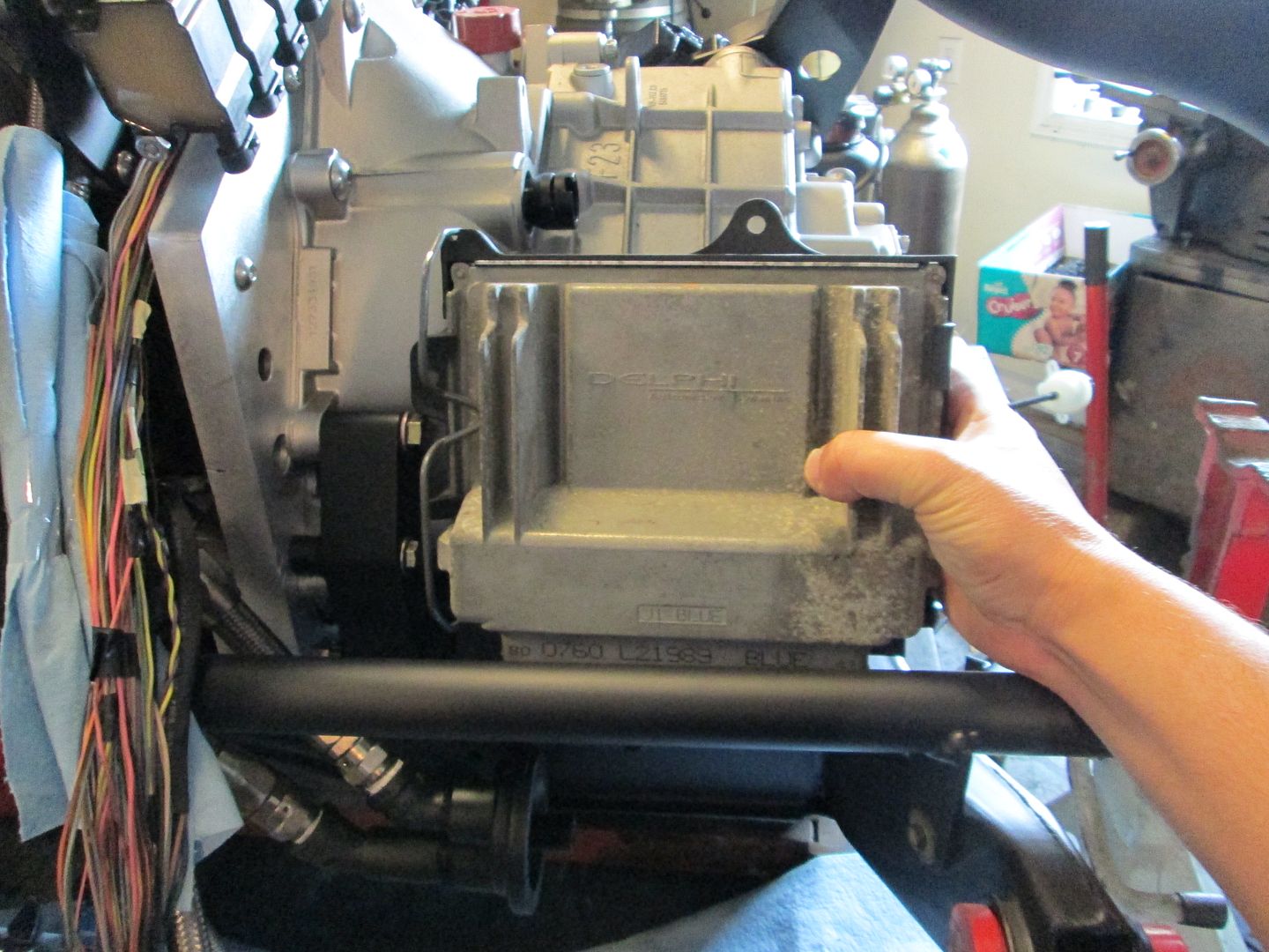
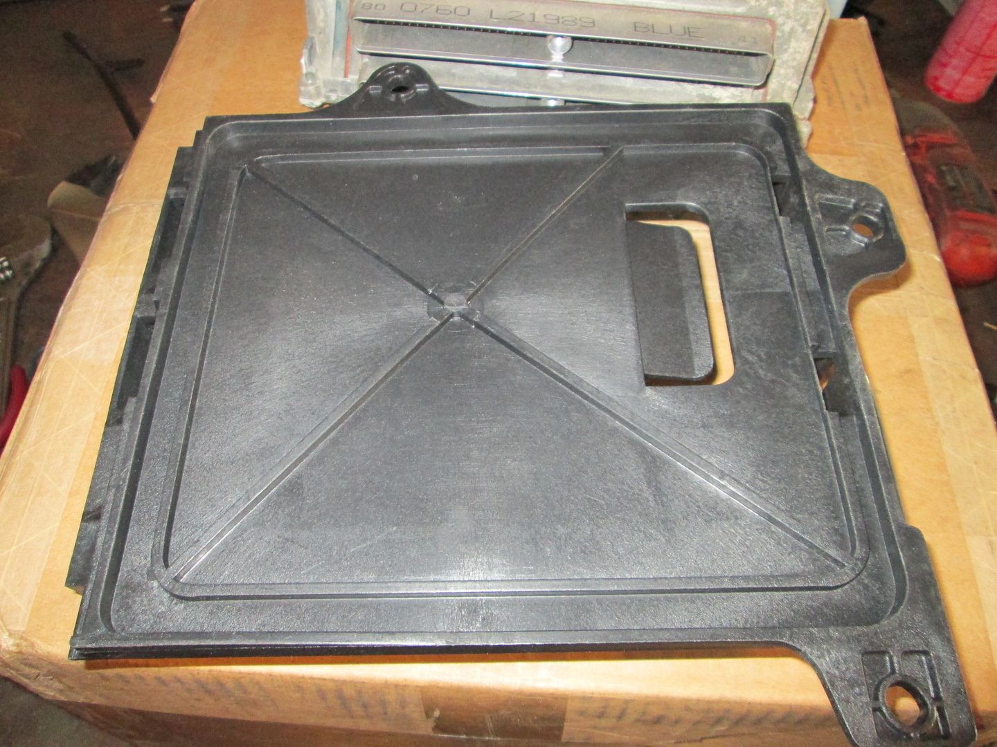
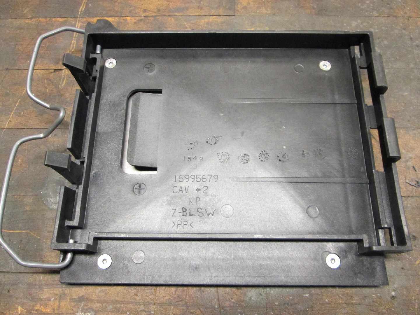
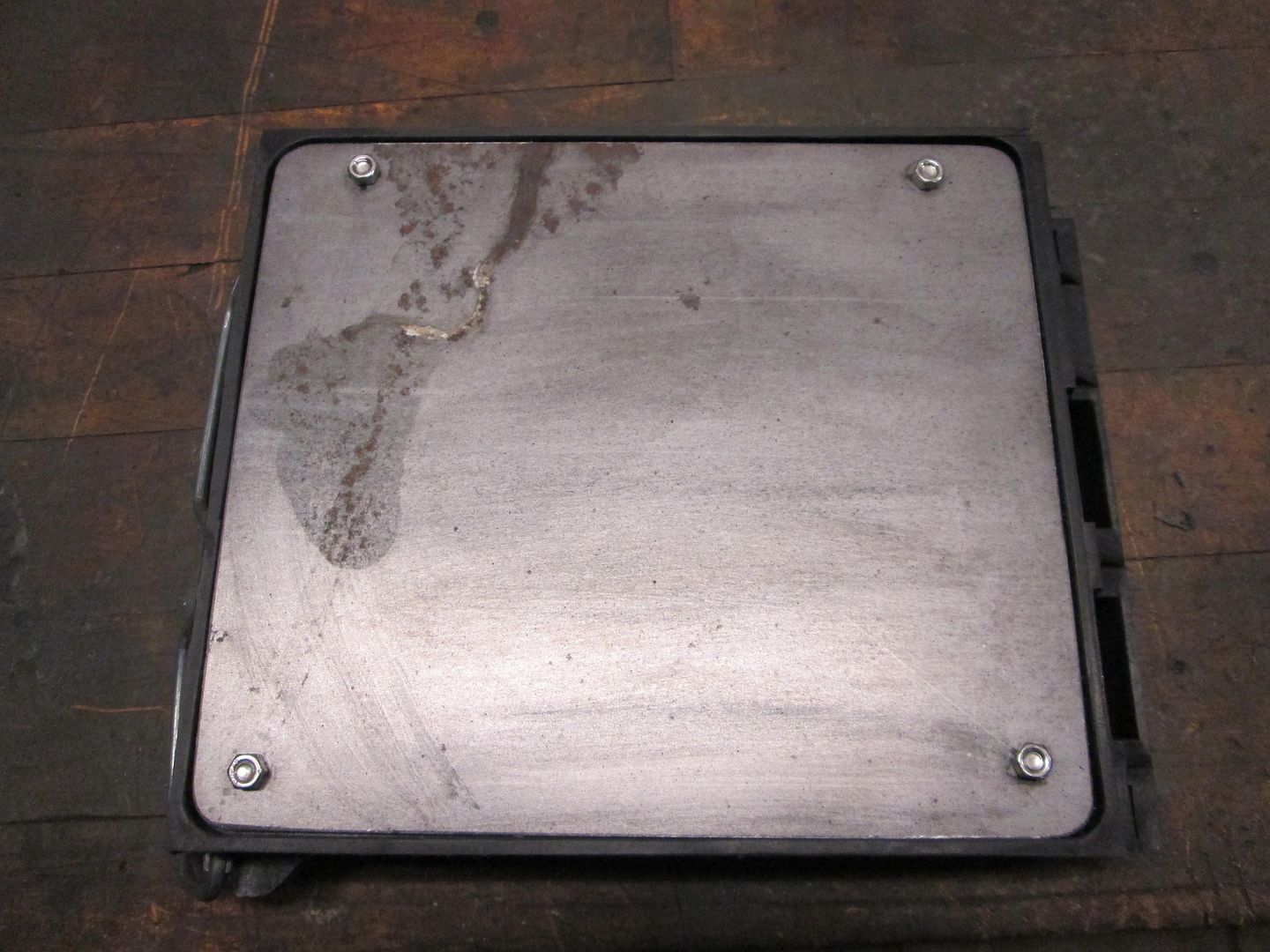
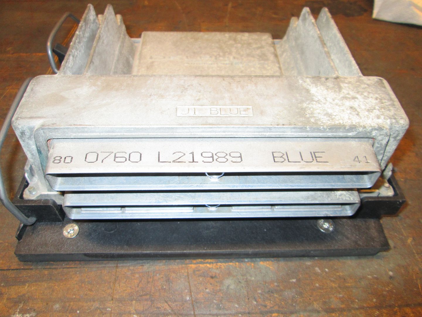
To hold the ECM, a truck ECM holder is used. Its pretty much flat and I can cut off all the stock mounting tabs and bolt it to a custom mounting bracket.
After Monday I will be all caught up on packages to ship and other customer orders and will have another 2 days off for the holiday to get more done on this.
|
|
|
|
Trinten
|
DEC 29, 05:02 PM
|
|
Thank you for the catch! You are right, it was a 140 amp Alternator. I don't know why I was thinking 230.
Looks so fricking sweet!! I really like how the black and silver/chrome is turning out.
Even though the paint is years from being done, I think I'm going to spring for a car cover now... help reduce the amount of leaves and crap that'll get down through the vents and make it look lousy -- I'm sure you found a few pounds of pine needles floating around everything.
Thanks again!!
|
|
|
|
fieroguru
|
JAN 01, 06:05 PM
|
|
A few parts have shown up since the last update.
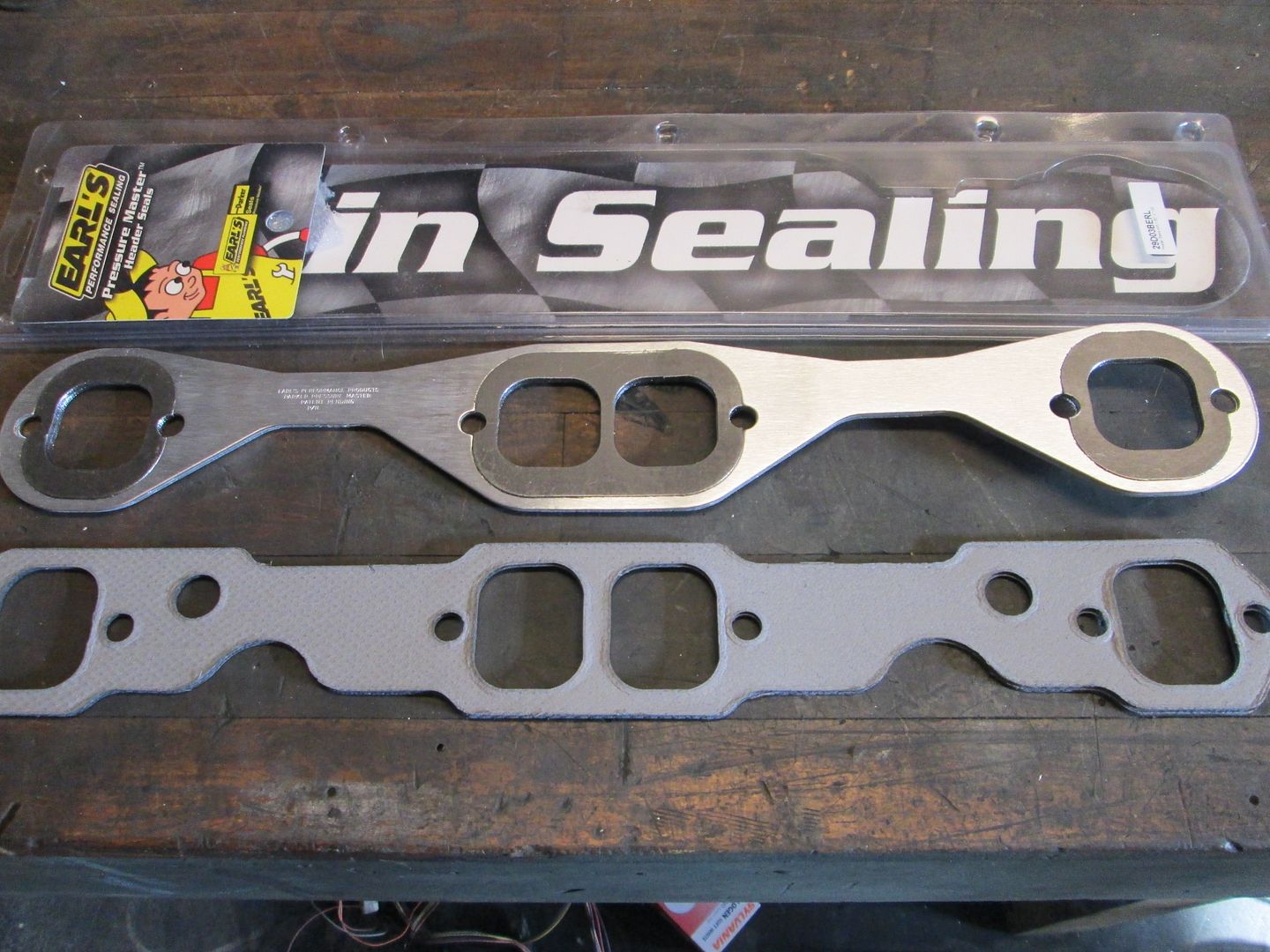
The exhaust gaskets. These have a removable gasket around the ports, so we will see how they do.
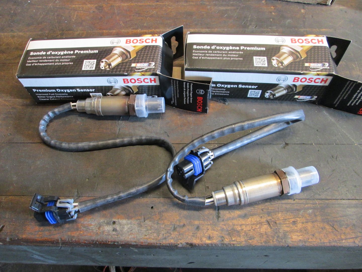
LS1 Camaro heated O2 sensors:
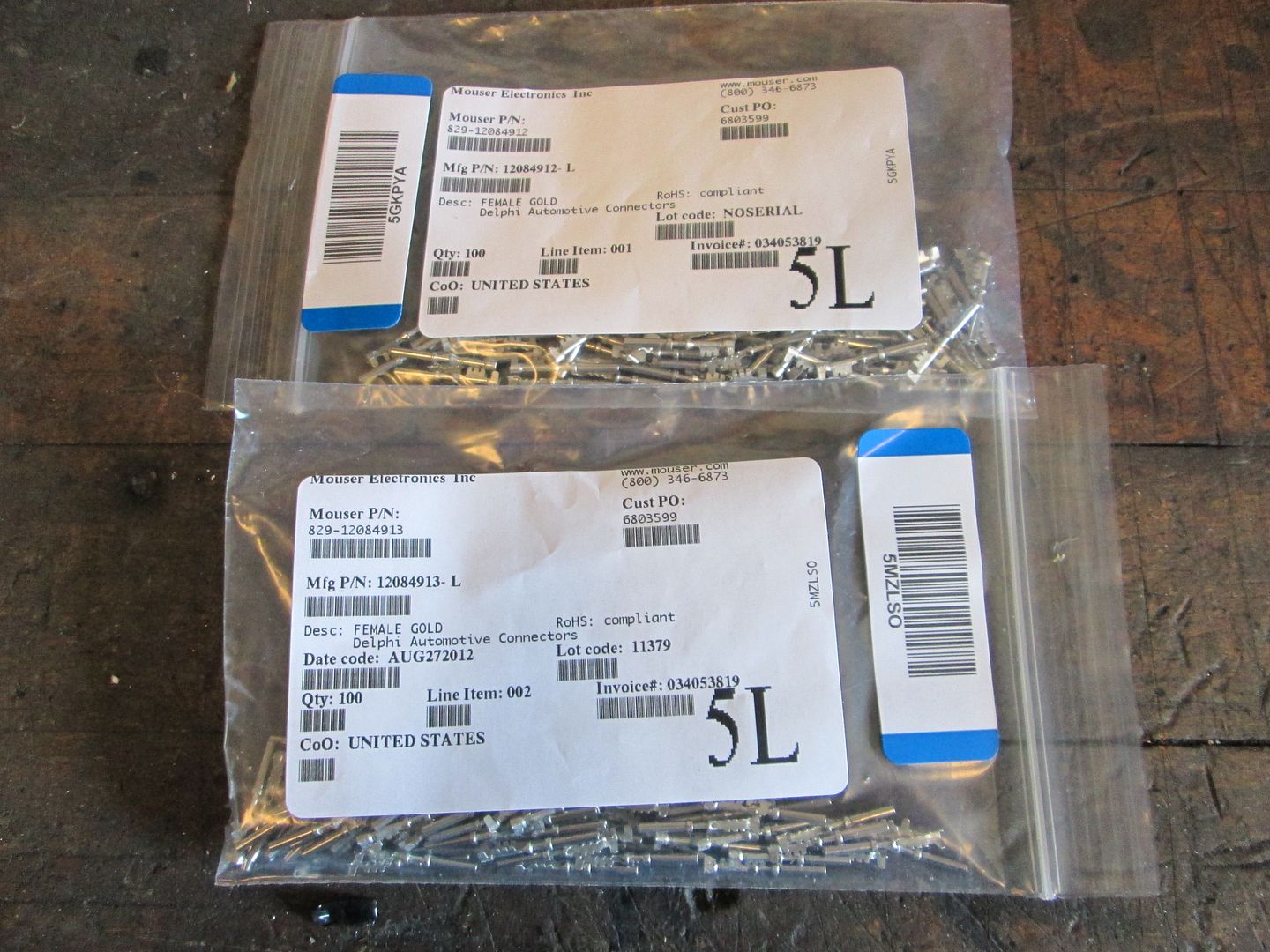
Pins for the ECM terminals:
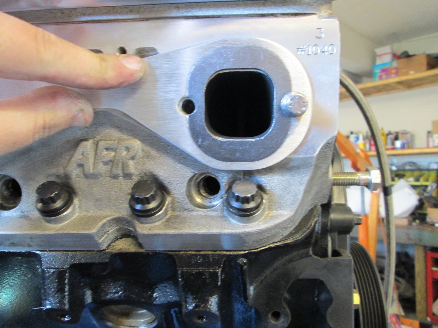
I test fitted the header gaskets on the rear of the engine. The headers have a larger (taller) taller opening.
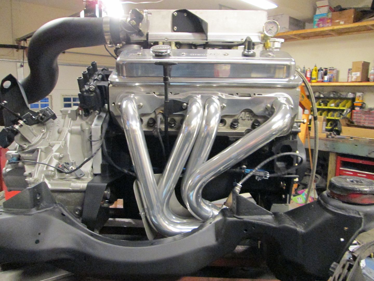
Then the gaskets, header, heat shield, O2 sensor and V-band clamp were all installed:

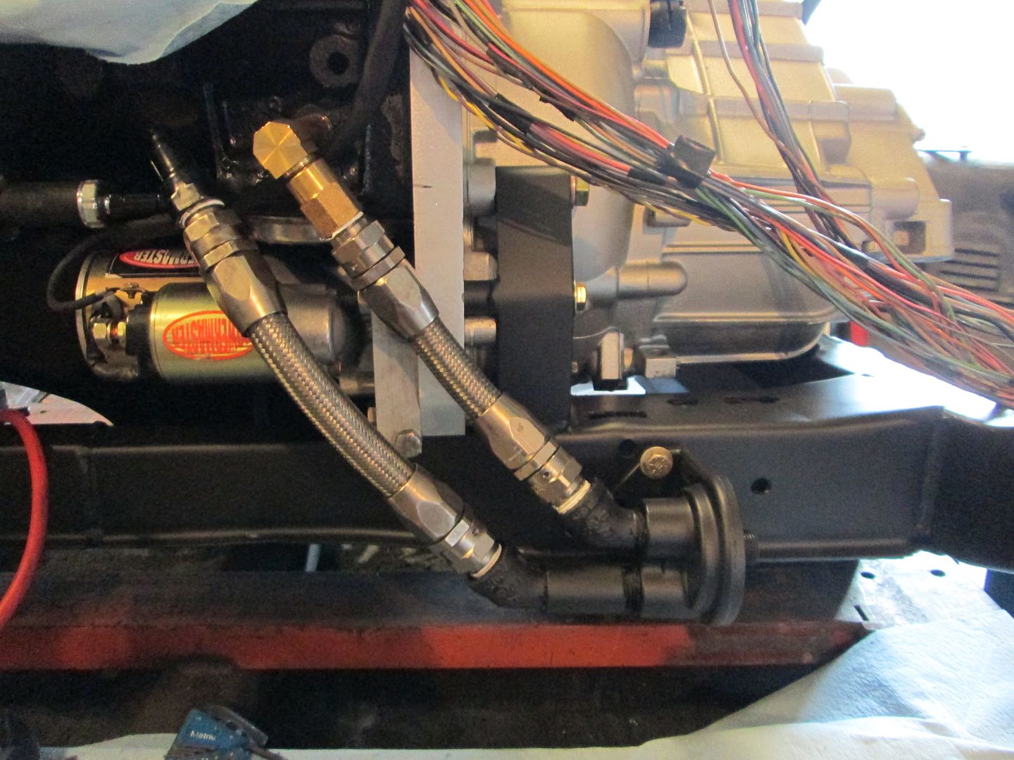
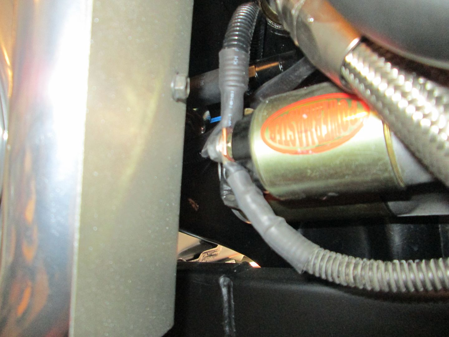
Before I could finish up the header install in the front, I had to finish the power cable from the alternator to the starter:
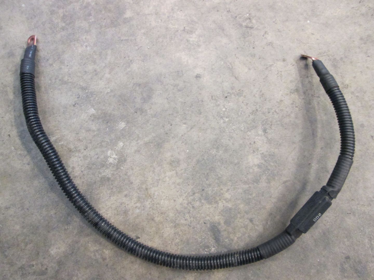
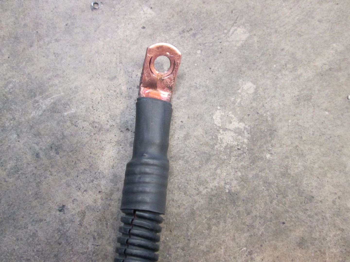
The cable coming off the starter and going to the bottom goes to the +12 junction by the 500 connector, but all the 500 terminations and this +12 junction will happen in the center console area. There will be 1 more cable connected to the starter - the +12 battery cable from the front of the car.
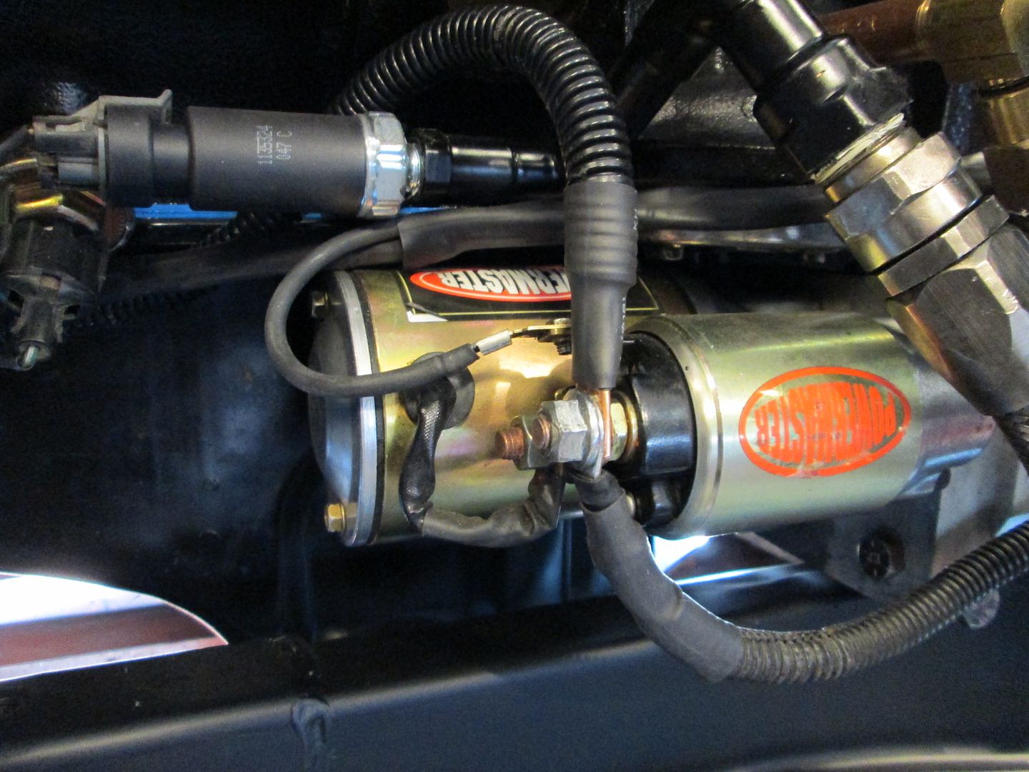
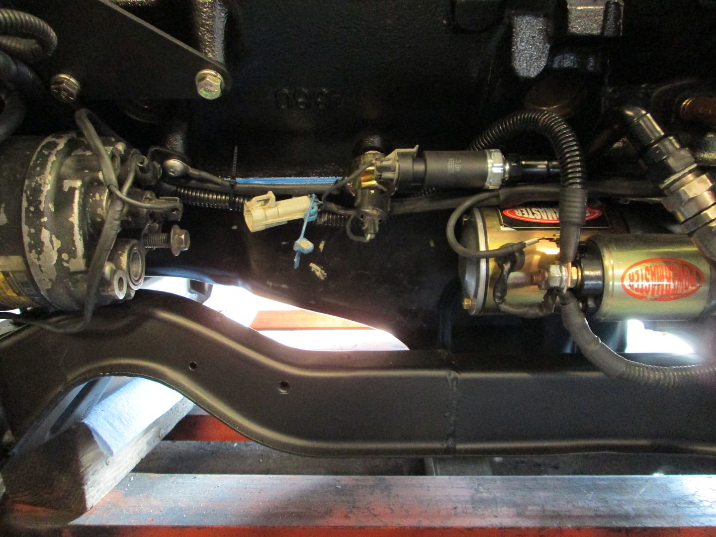
Front header, heat shield, O2 sensor and V-band clamp installed:
Here is the gap between the heat shield and the starter terminal:
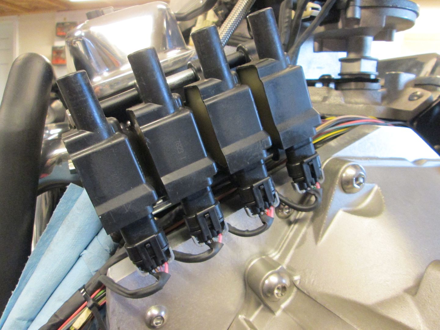
Then I went back to wiring. Bank 1 coils are loomed up and ready for terminating at the other ends.
I started on Bank 2, but it isn't ready for pictures yet.
|
|
|
|
Trinten
|
JAN 01, 06:39 PM
|
|
Oh wow! Even with the o2 sensors that close to the exhaust, they still needed to be the heated style? Damn, I didn't realize their required operating temps were that high! I would have bought the wrong ones... probably caused a bunch of issues when trying to get it tuned.
And this, everyone, is one of the many reasons why I ask people who know waaay more than I do to work on this thing. lol
Looking incredibly awesome...
|
|
|
|
fieroguru
|
JAN 04, 06:15 PM
|
|
With OBD2 the O2 sensors are heated to make their readings more consistent. I use them on pretty much every swap these days.
Back to the wiring...
Bank 2 coils are wired up:
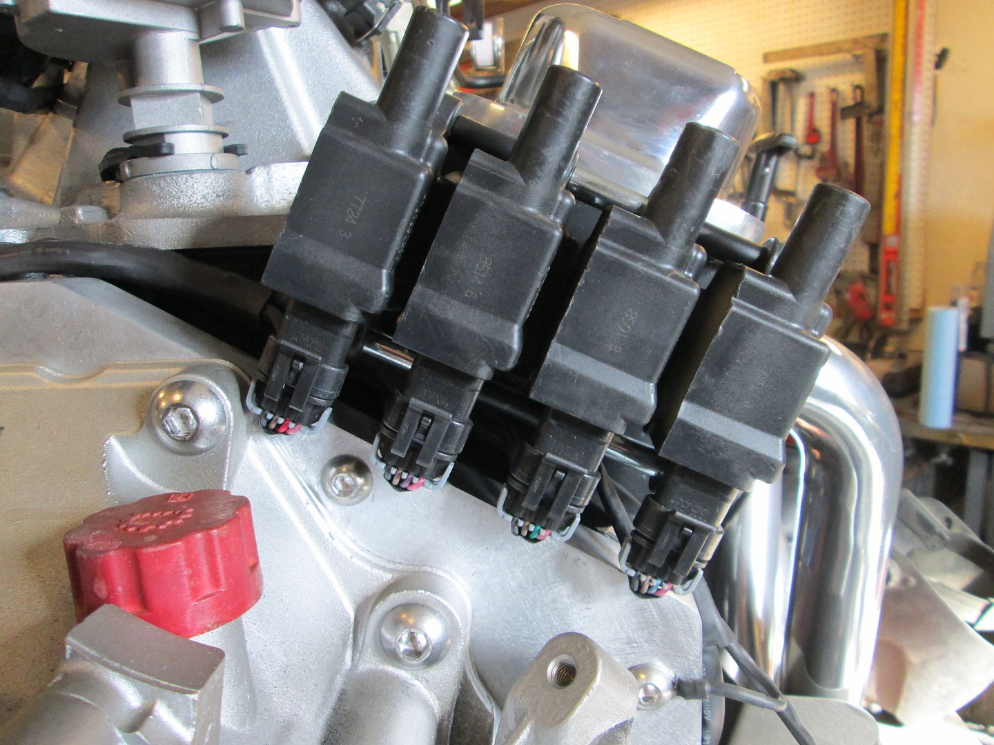
Coil sub harness joining the main harness:
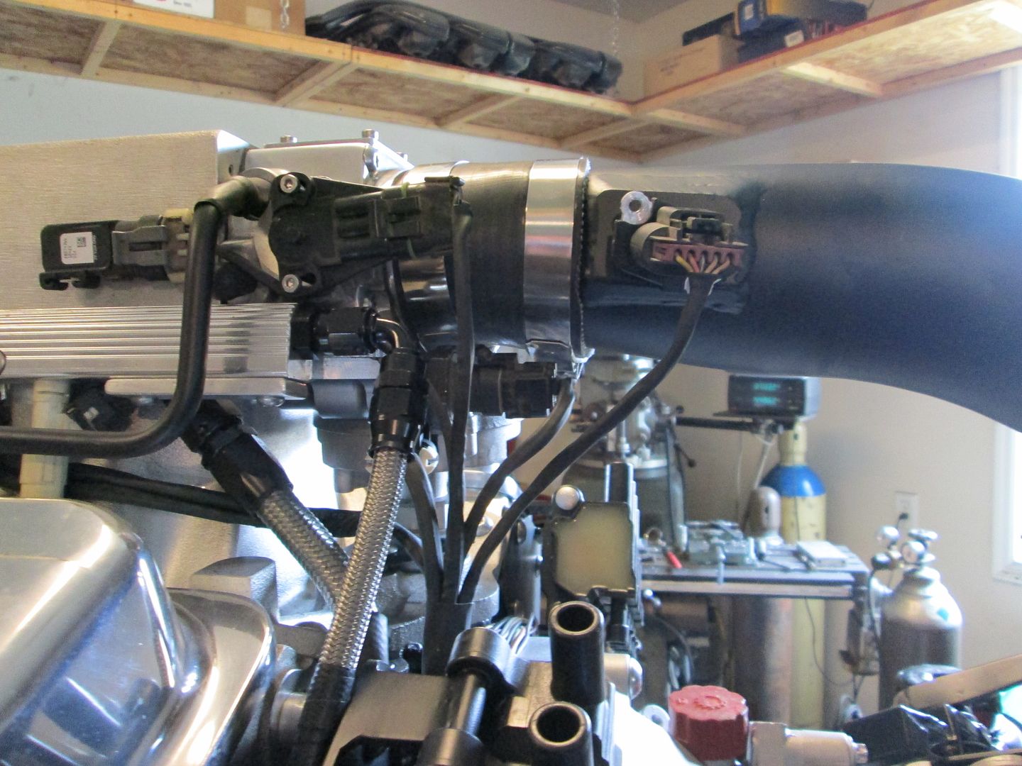
Top side sub harness joining the main harness:
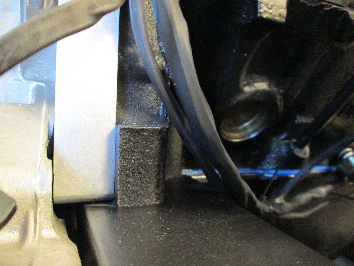
Here you can see the front sub harness join the main harness and then the wires split with one set going to the ECM area and the others pull aside to go inside the passenger area:
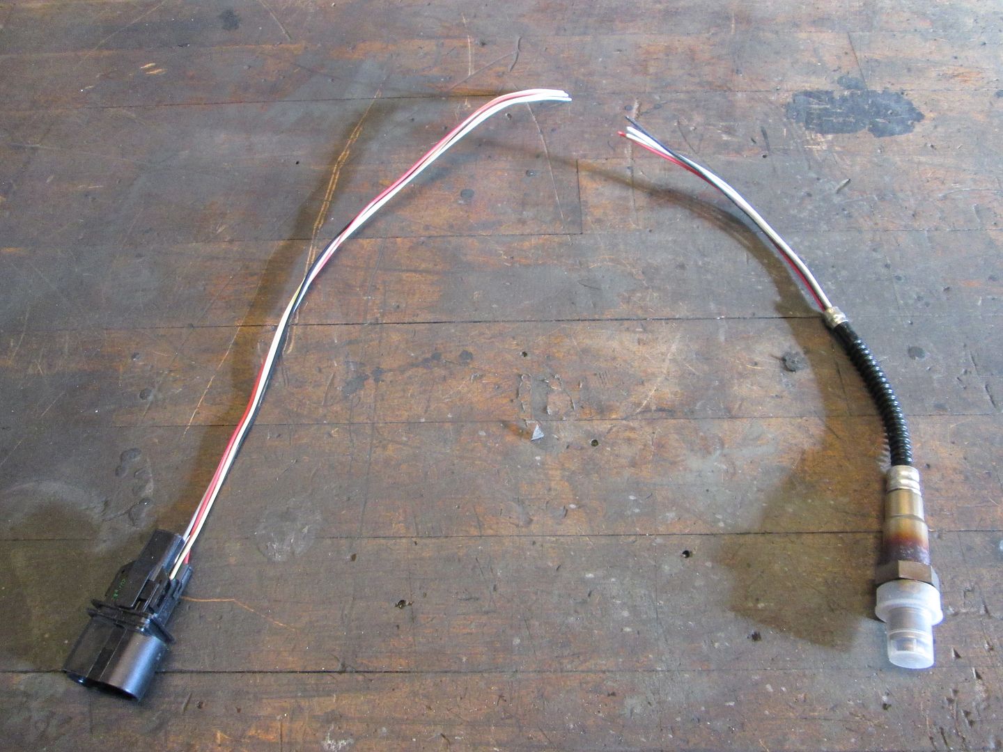
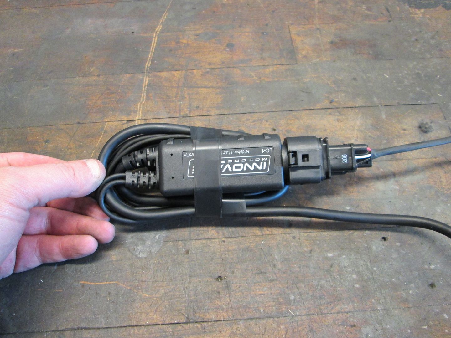
Then I started working on the wideband... more wiring. The wire length from the wideband O2 sensor to the controller is quite short and would require the controlled to be in the engine bay along the engine. The controller has 2 cables that are not needed, so they have to be coiled up and the other cable with the connection wires is too long... so I coil things up like this:
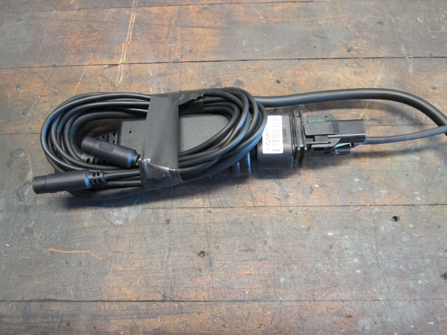
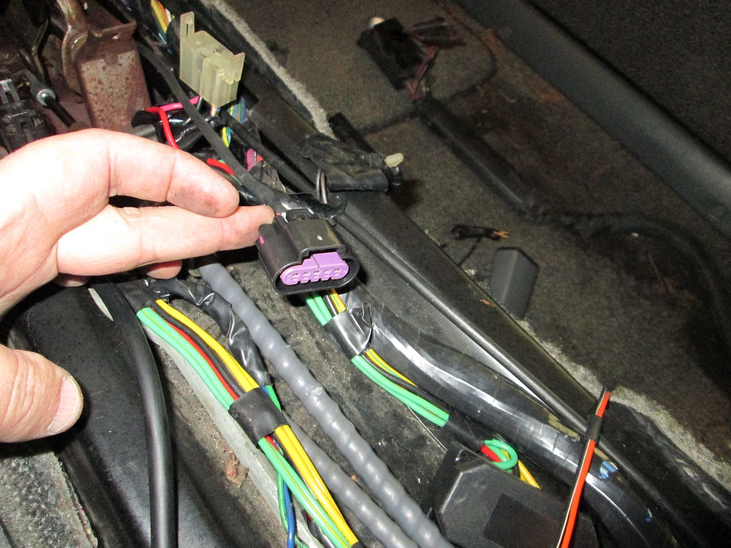
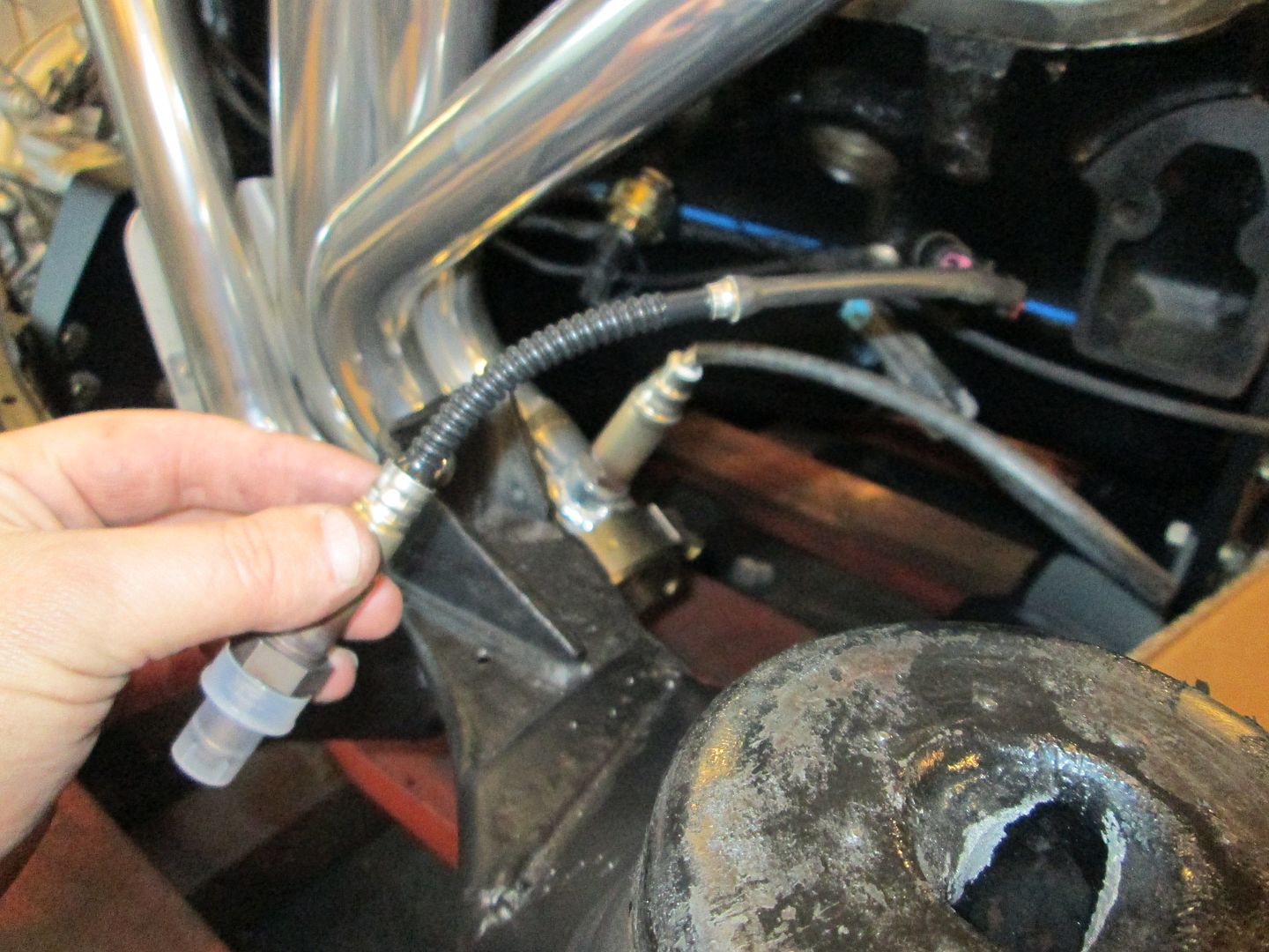
Now to put the controller inside, I have to extend the O2 sensor wires, so start with a simple cut:
Use some matching male/female connector ends to repair the cut:
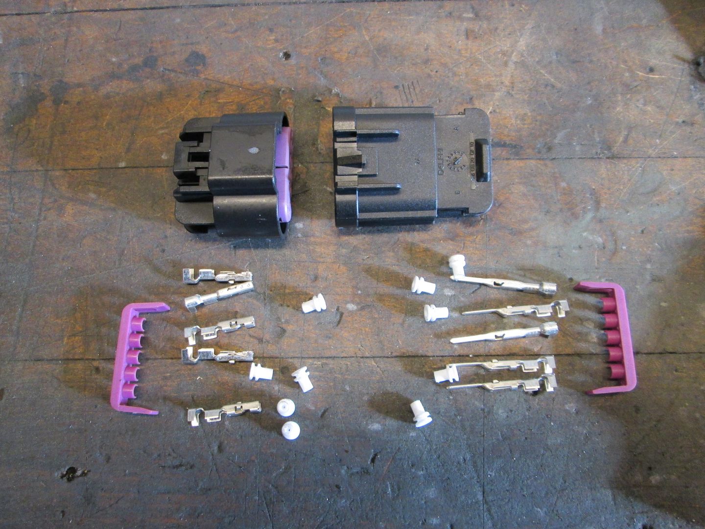
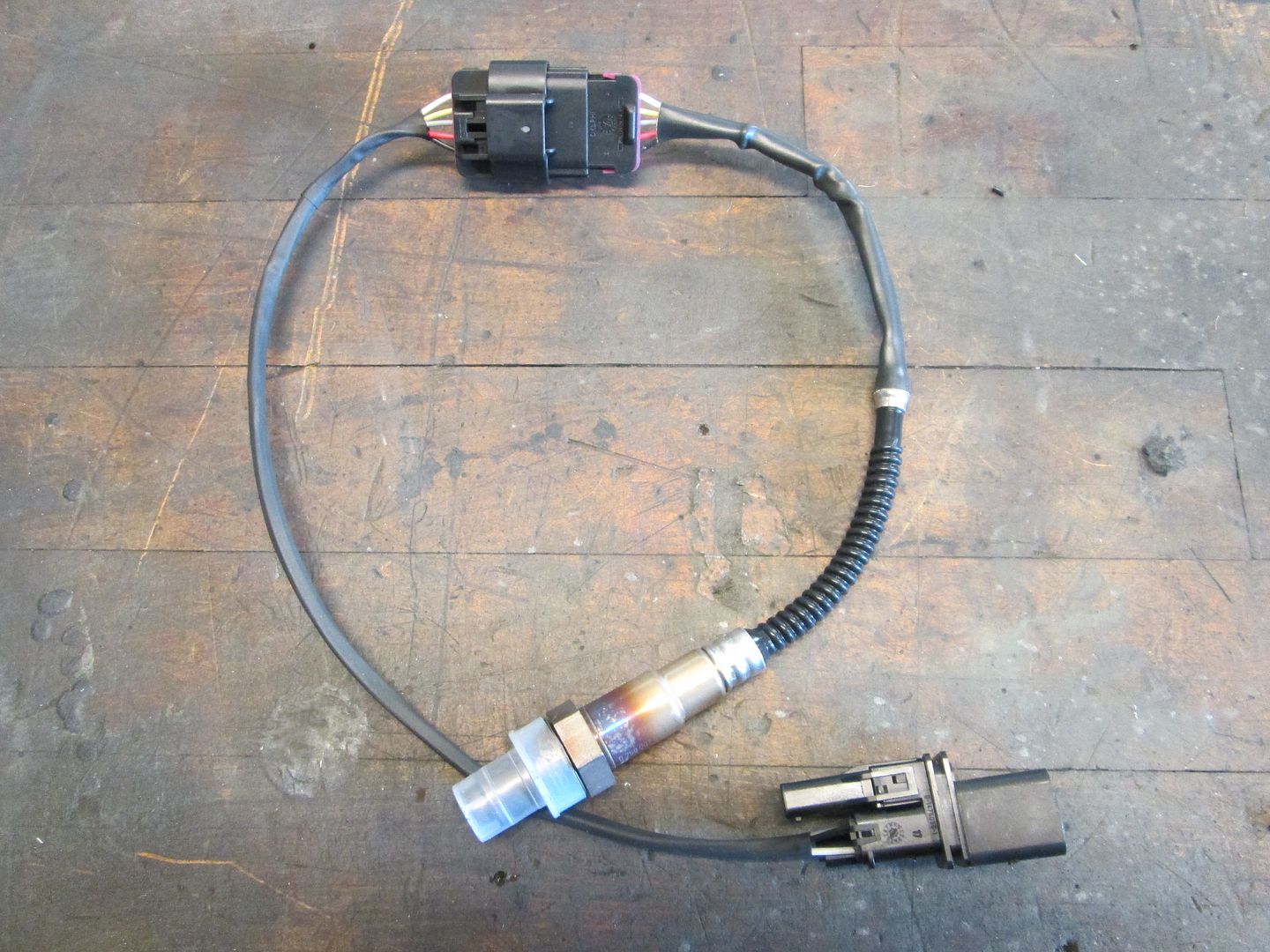
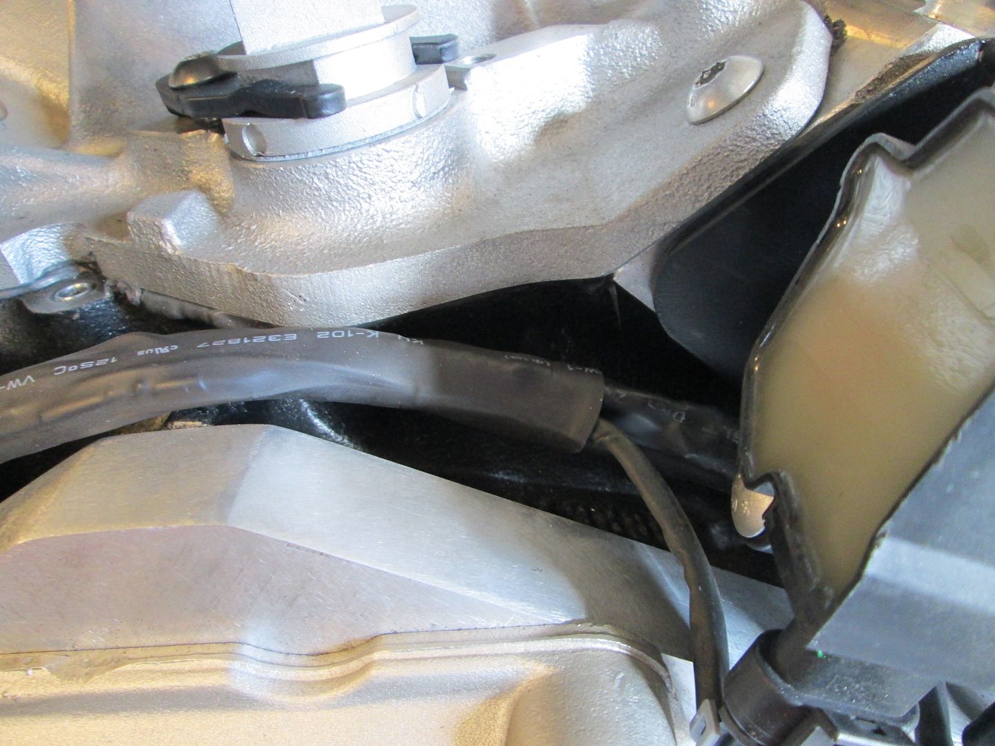
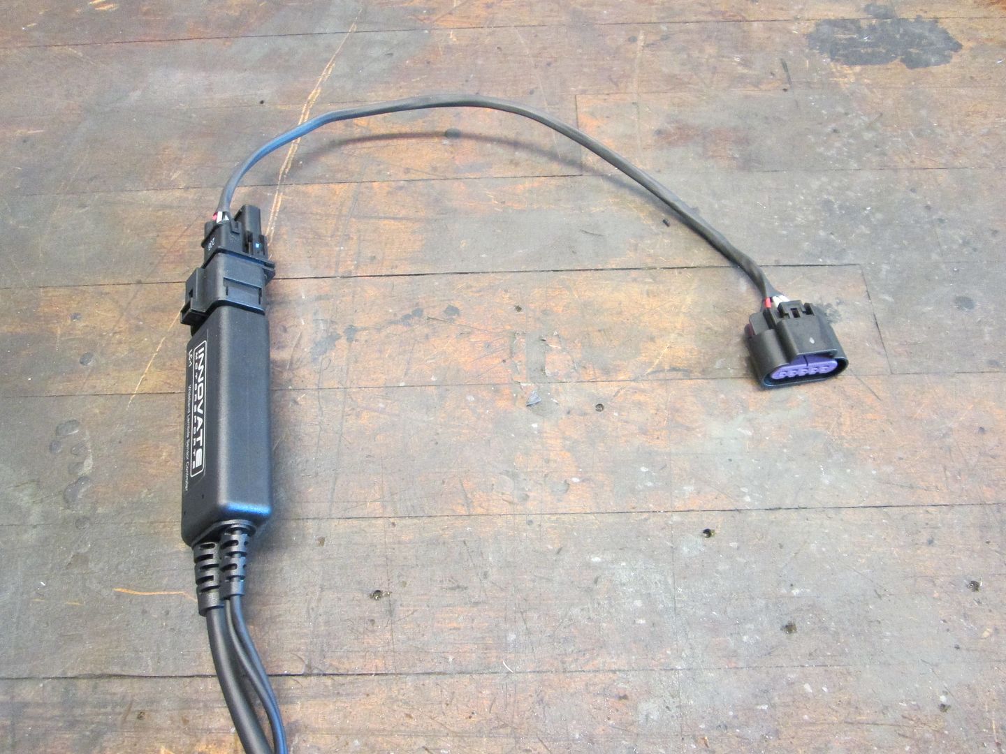
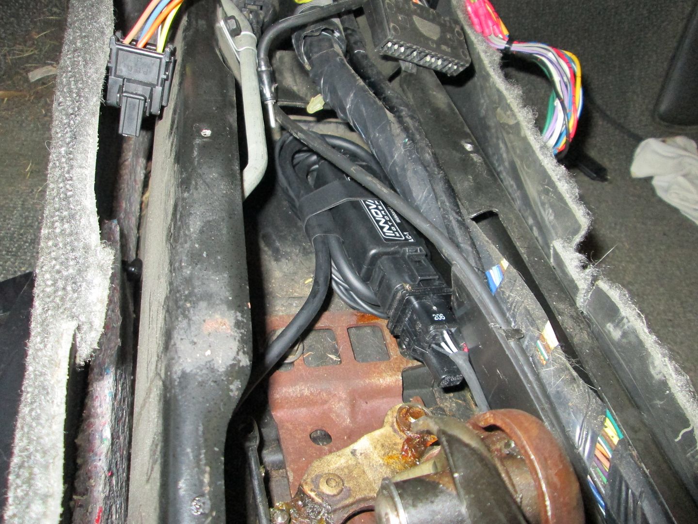
Here is the controller with the new connector end and the approximate location it will be located. The O2 harness runs on the stationary side of the shifter, the other cable will be wire tied to the vacuum tube to keep it away from the shifter:

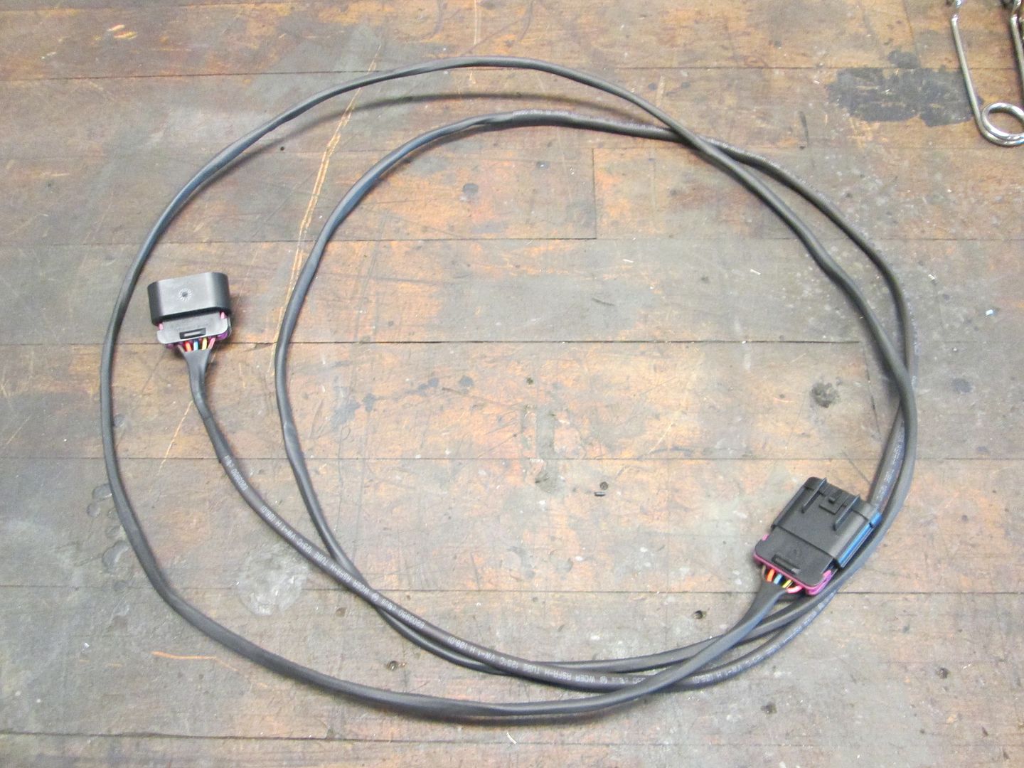
While in the car, I measured the distance from the connector to the firewall so I can make the jumper section of wire using the same connector ends:
Here is an approximate location for the wideband O2 sensor:
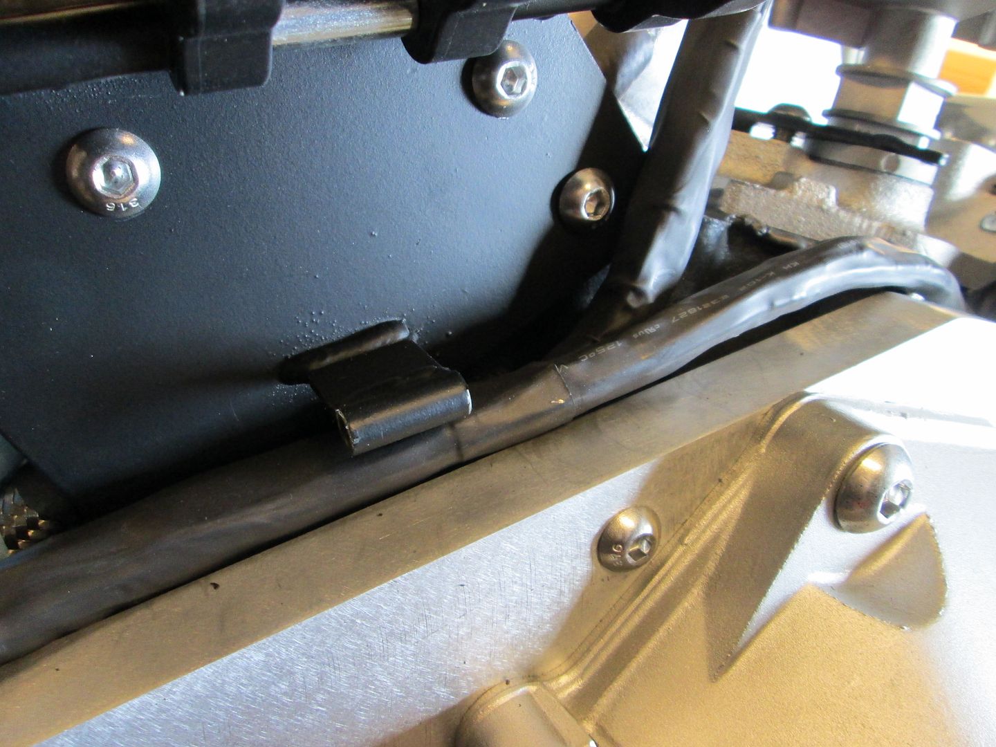
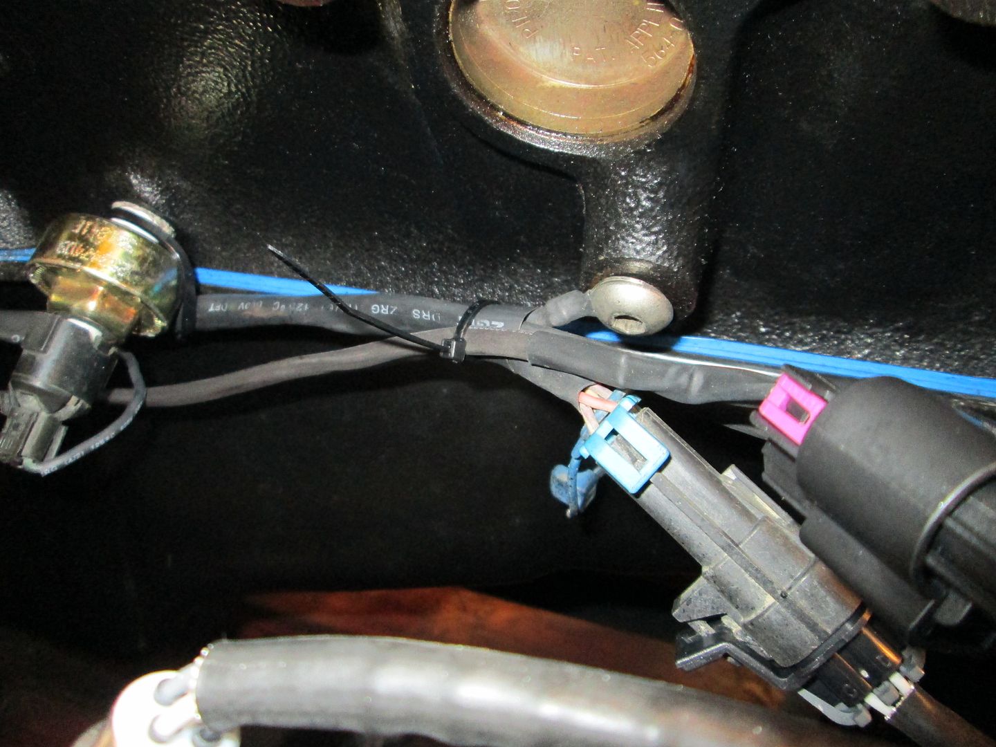
Then I wire tied the wideband sub harness to the engine harness:
Here is the other end ready to go into the car:

On Sunday I am going to take a short break from wiring and fab up the ecm bracket. Once that's done, I can start terminating the wires at the ecm.
|
|
|
|
fieroguru
|
JAN 10, 07:26 PM
|
|
I am glad the single digit temps have left KY!
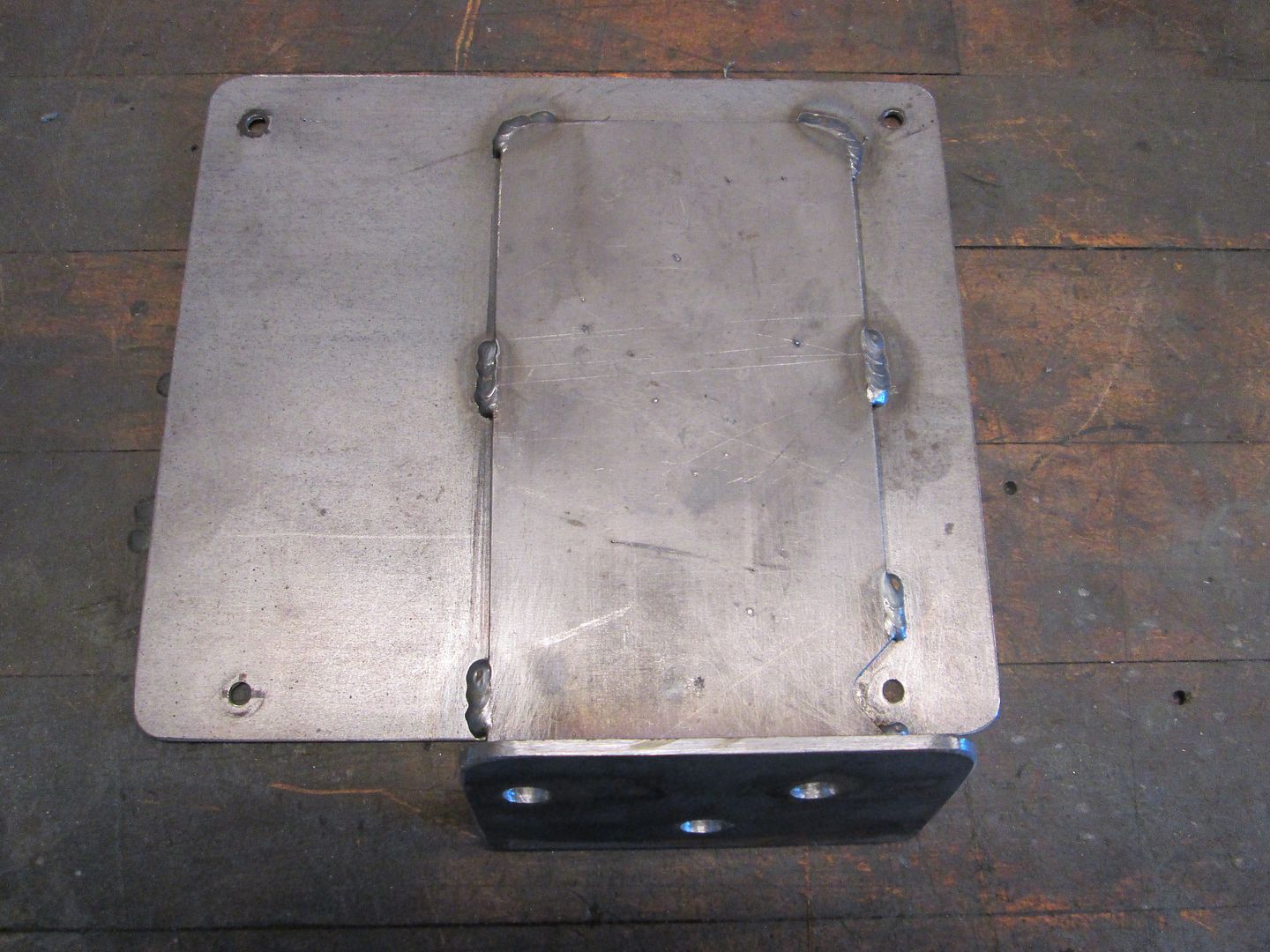
Started on the ECM bracket. Cut all the plastic tabs off the ecm holder, cut out a piece of 16ga to bolt to the back, marked the holes, countersunk the ones on the holder side (so they can't touch the ecm and ground the case), and then bolted it together:
|
|
|
|
fieroguru
|
JAN 11, 01:21 PM
|
|
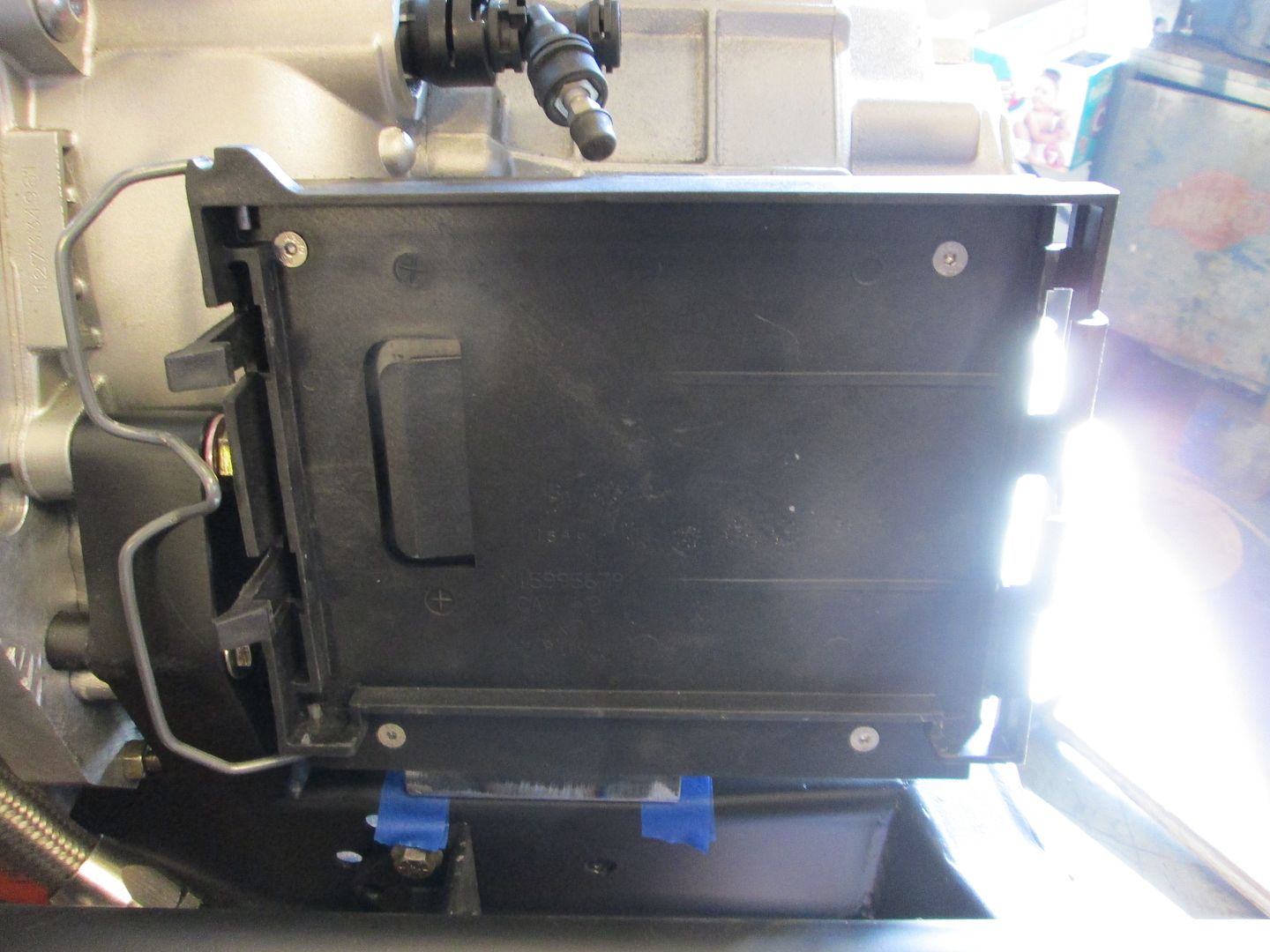
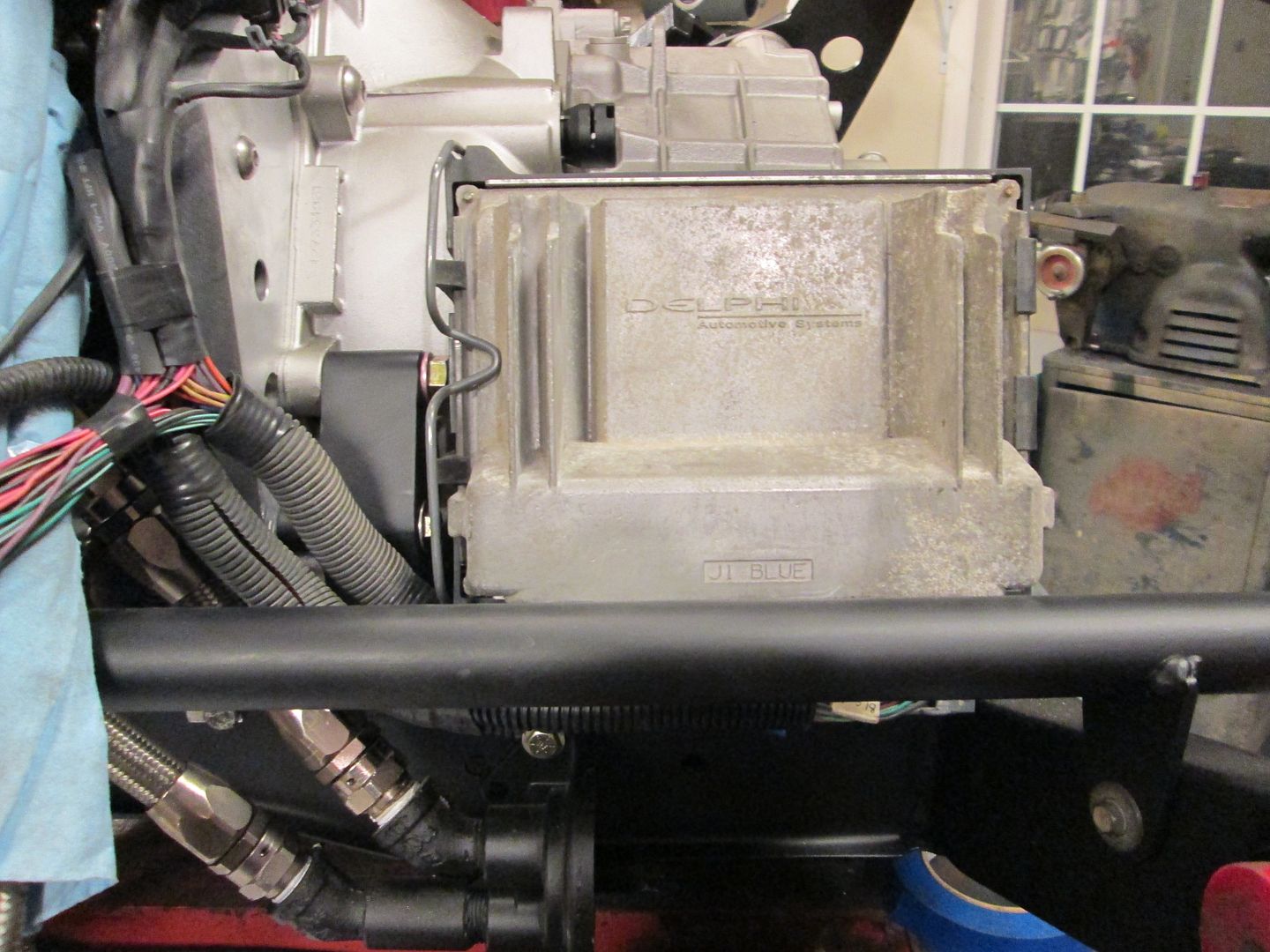
The ECM mount is now done, I will paint it once the wiring terminations at the ecm are done.
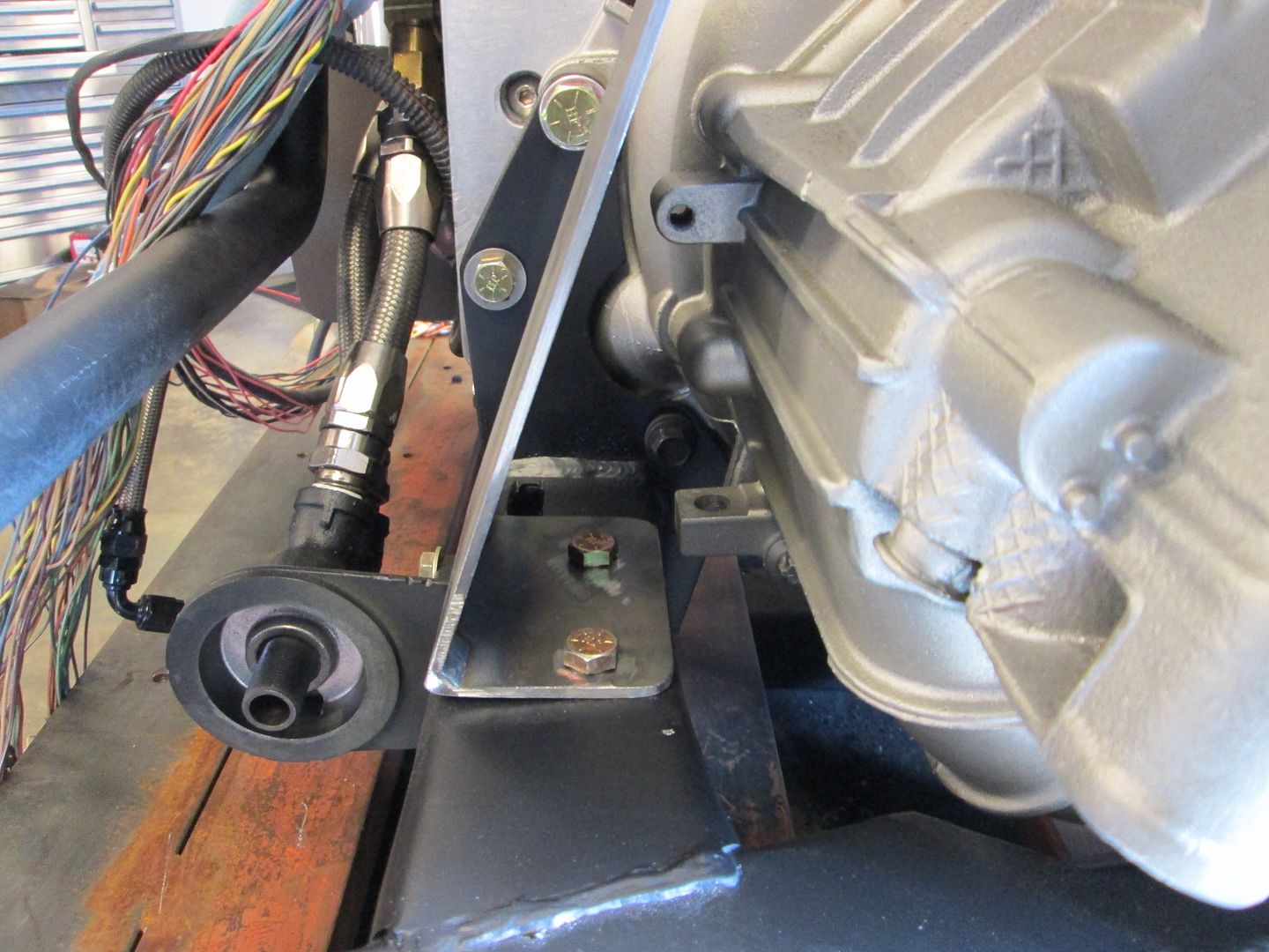
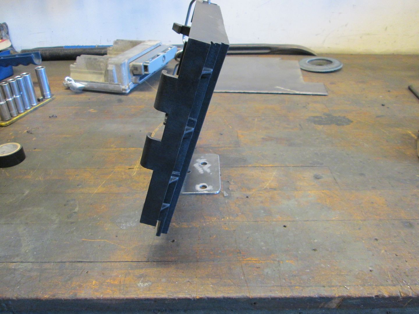
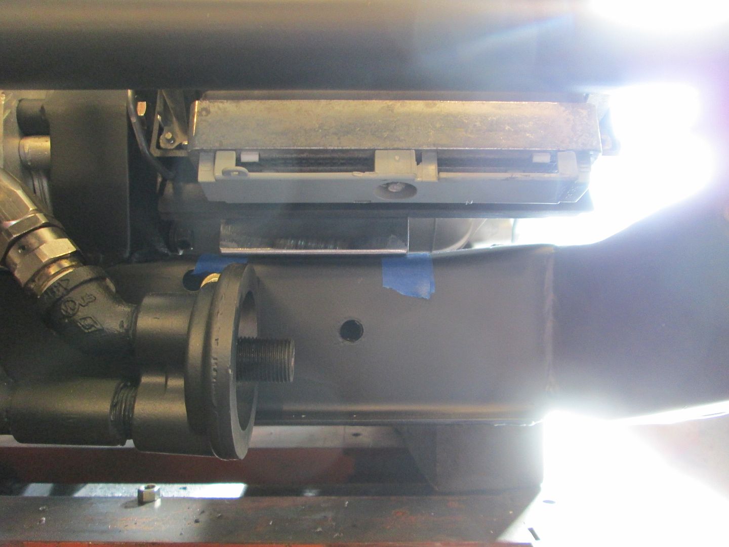
Fabbed up this bracket to bolt to the cradle and weld to the back plate on the ecm holder:


|
|
|
|
fieroguru
|
JAN 11, 08:18 PM
|
|
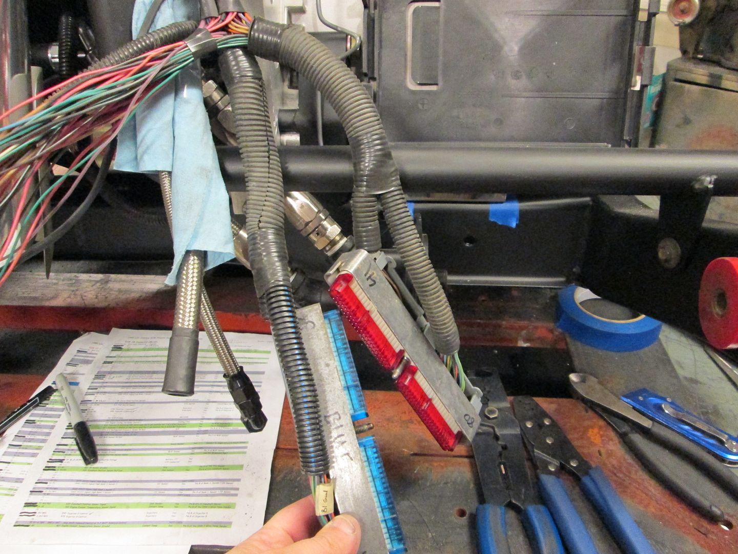
All wires have been terminated at ecm:
|
|
|
|
Trinten
|
JAN 12, 10:55 AM
|
|
Nice!
I saw some papers floating around there with some highlighting - was tracing things to rewire a tremendous hassle? I think I had seen all the tracing/crossing work you had to do on your swap, so I was just hoping this was not that intense.
Thank you for the great tutorial. I really like the solution came up with for the ECM!
|
|
|
|