|
| Blooze Own: An F355 Six Speed N* Build Thread (Page 28/126) |

|
dratts
|
NOV 20, 11:07 AM
|
|
|
Your IFG body will require a 3" stretch on your wheel base. The easiest way is to stretch the cradle and move the top of the struts back rather than cutting the car in half and rewelding it. The N* requires that you move the front crossbar on the cradle forward 3". I've never heard of it done but why not do the stretch on the cradle behind the front crossbar? That way you kill two birds with one stone. (If you like killing birds with stones) My AD355 body has the rear wheel wells moved forward 3" so that I maintain the stock wheel base. If I were doing it over I would use a stock wheelbase body and stretch the cradle instead. Like everybody says, WHAT A GORGEOUS DRIVETRAIN!!
|
|
|
|
kikinz24
|
NOV 20, 03:11 PM
|
|
|
i will say it looks beautiful so far. everyone i know asks me why my motor is still sitting in the garage andnot running in the car and its beacuse im also taking the time to make everything fit perfet for the best look possible. but your build surpasses mine by far.
|
|
|
|
Bloozberry
|
NOV 23, 07:57 PM
|
|
Thanks for your comments kikinz24. I’m starting to feel the same way about my project… the completion date just keeps stretching out there on the horizon.
Speaking of stretching, Dratts, I realize that the wheelbase on my car has to be lengthened 3” to accommodate the body. In fact luckily for me, the previous owner already took care of that and did a remarkably nice job doing it too. Mine was stretched in the customary location just behind the cockpit. I’m not sure your idea of stretching the cradle would work. You would still need to move the strut towers back by an equal amount, which would defeat the purpose and make it a lot harder to do.
Anyways, I’ve got more pictures to share so here we go: Once I had drawn out the shape of the jackshaft bearing mount, I wanted to make one out of some scrap hardwood I had lying around to confirm the dimensions were accurate. I cut out the cardboard version and used it to trace the pattern on a 1” thick piece of wood. Then I used a pair of Forstner drill bits to cut the bearing recesses, and a band saw to cut the outside shape.
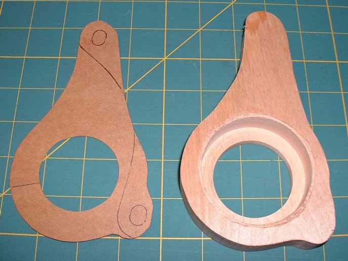
I used hardwood so I could drill and tap the mounting holes and actually use them. Then I pressed the bearing into the recess and then the jackshaft into the bearing, and finally test fitted the wooden mount to the engine bracket.
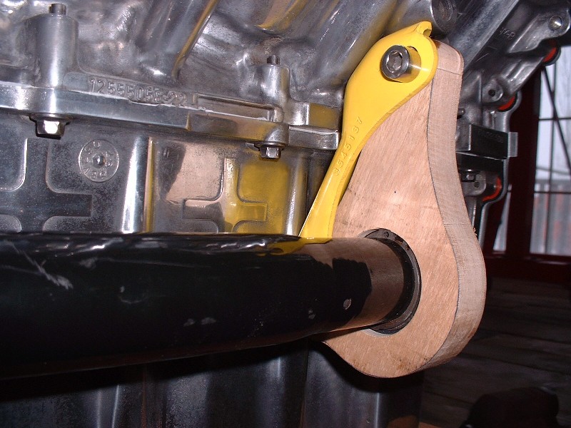
I’m glad I took the time to do this extra step because even though I could get the bearing mount to fit, it forced the axle to be raised an 1/8” higher at the bearing end than it was at the transmission end. By raising the mounting holes 1/8” on the final design, the axle would line up perfectly level.
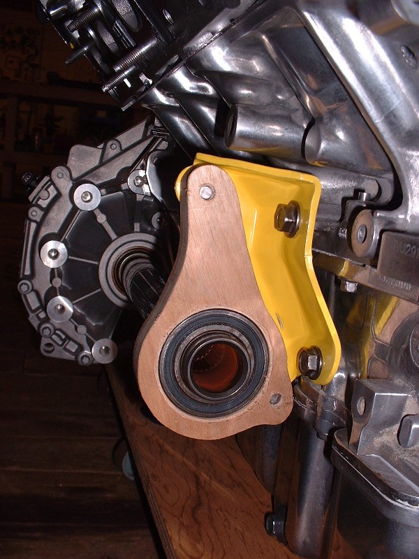
Oh, and here’s another reason why it was a good idea… can anyone spot the problem?
With the drawing finalized, I took a run out to my favorite machine shop where for $60 they sold me a 7” X 3.75” X 1” block of 6061-T6 aluminum, and machined the holes for the bearing. You gotta like that!
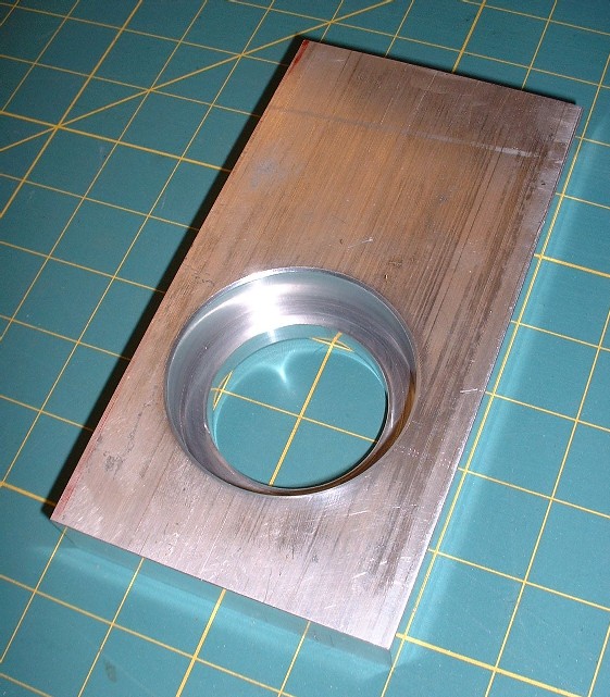
It was nice that there were some finely finished square edges on the block since that made locating the mounting holes a piece of cake. I double and triple-checked my measurements and decided it was time to make some aluminum shavings of my own. If you decide to make something like this yourself, make sure you use a drill press otherwise you’ll surely end up with holes that aren’t parallel.
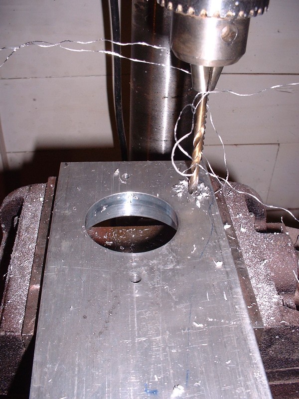
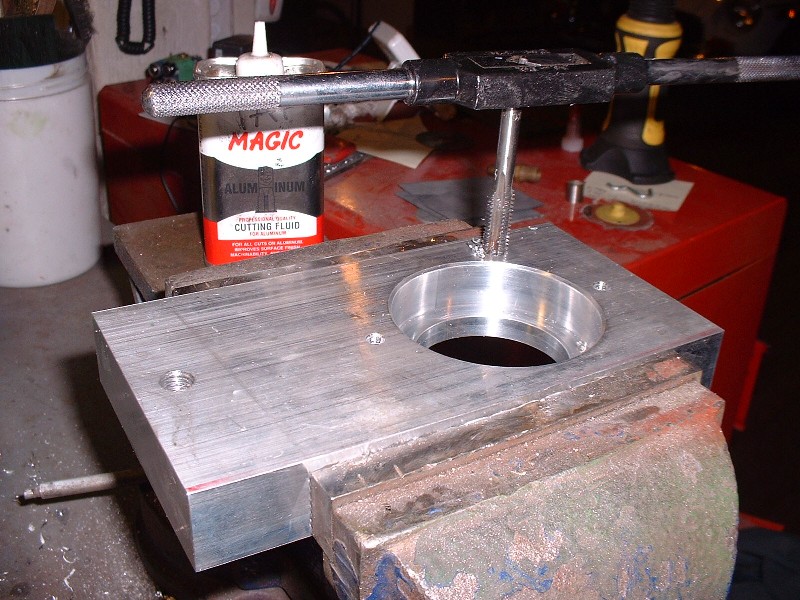
Then I tapped the two sets of holes for metric threads since everything else on the engine and car would be metric. I tapped the mounting holes for M10 X 1.5 and the little bearing retainer holes for M6 X 1.0 if I recall correctly. I almost ran out of length for the smaller tap while trying to cut the threads all the way through the 1” material.
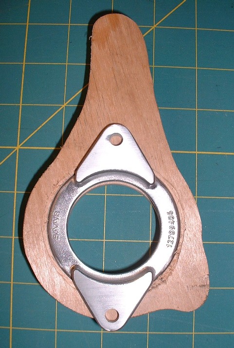
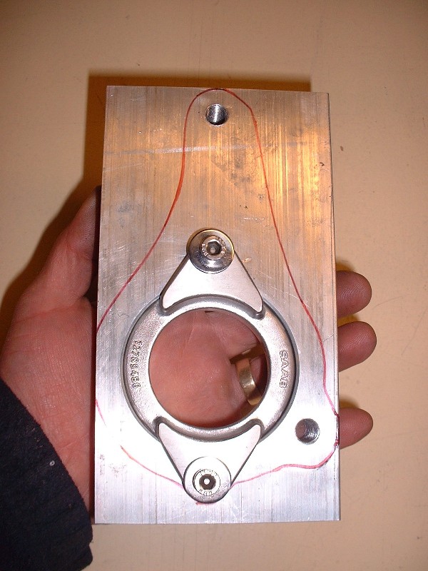
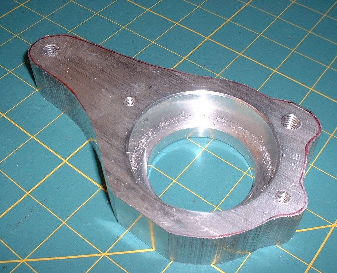
Once that was done, I transferred the final outline of the bearing mount onto the block of aluminum and test fit the bearing retainer just to make a prettier picture.
Then it was time for this thing to shed some weight! Unlike some of the richer people here on PFF with multi-axis computer numerically controlled milling machines, I had to resort to using my trusty-dusty band saw to make quick work out of getting the rough shape to come out. My machine shop asked how many I was going to make and offered to enter the design in Solidworks for a nominal fee, but I couldn't see a big market for it and besides, I wanted it, like now. As I cut through the solid block of aluminum, I started to feel a little like Michelangelo probably did as he was carving the statue of David out of marble, except I was probably more excited.
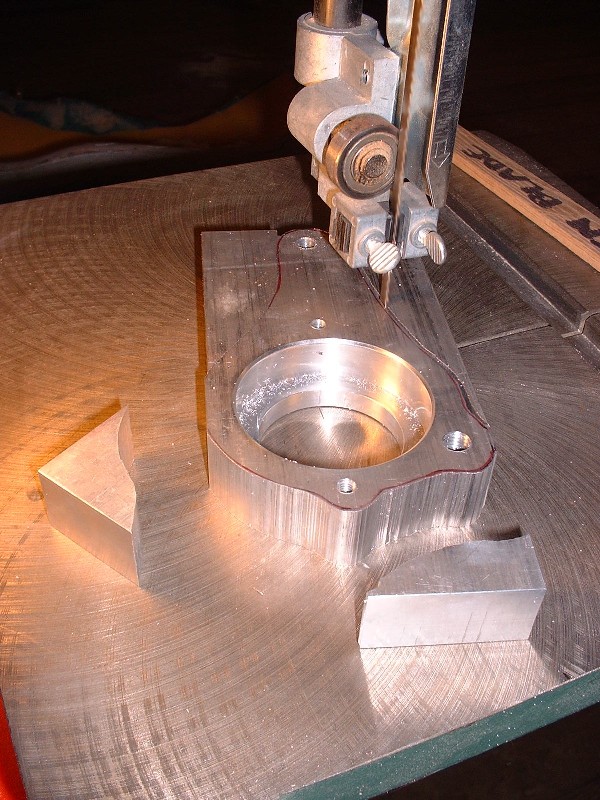
Here’s the rough cut bearing mount after surgery. It almost looks like a connecting rod… hmmmmm….
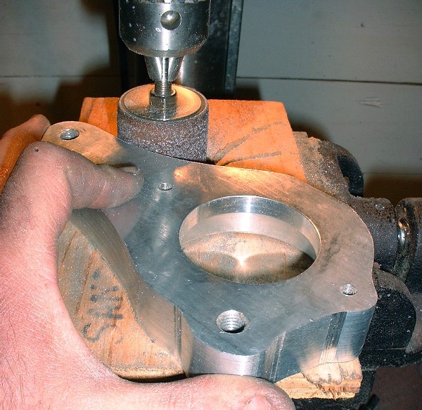
A few more operations to get rid of the scars and it wasn’t long before this thing started to look like it might actually belong on my engine. I used a 50 grit sanding drum initially on the edges, and then traded up for one with 100 grit. The drums lasted surprisingly long, in fact I only went through one of each.
|
|
|
|
doublec4
|
NOV 24, 09:39 AM
|
|
|
Nice solution, I love the ingenuity
|
|
|
|
aeffertz
|
NOV 25, 05:19 PM
|
|
|
|
|
crzyone
|
NOV 25, 06:22 PM
|
|
I have not posted on this forum in a long time but I felt I had to. Excellent thread man! It makes me want to build another Northstar Fiero. I sold mine after I had most of the bugs worked out of the Big Stuff 3 ecu on a 2003 engine. I regret selling it and this thread has me on e-bay looking for an engine to build.
 ------------------

Buy a fiero, become a mechanic
3.4 dohc Install
Sub Install
Northstar Install
|
|
|
|
Fiero Thomas
|
NOV 25, 07:31 PM
|
|
|
|
|
Bloozberry
|
NOV 26, 01:47 PM
|
|
Thanks guys, I appreciate the feedback… it keeps me motivated! Hey Crzyone, it’s funny what comes around, goes around. You were one of the initial guys with your build thread that inspired me to build a Northstar! I poured over a lot of threads before deciding to take the plunge and yours was one of them.
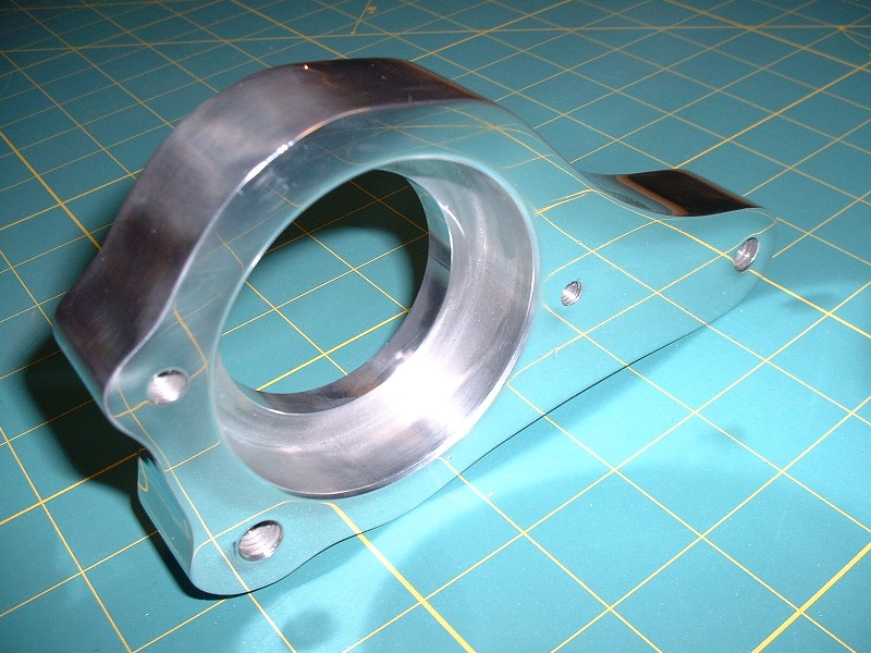
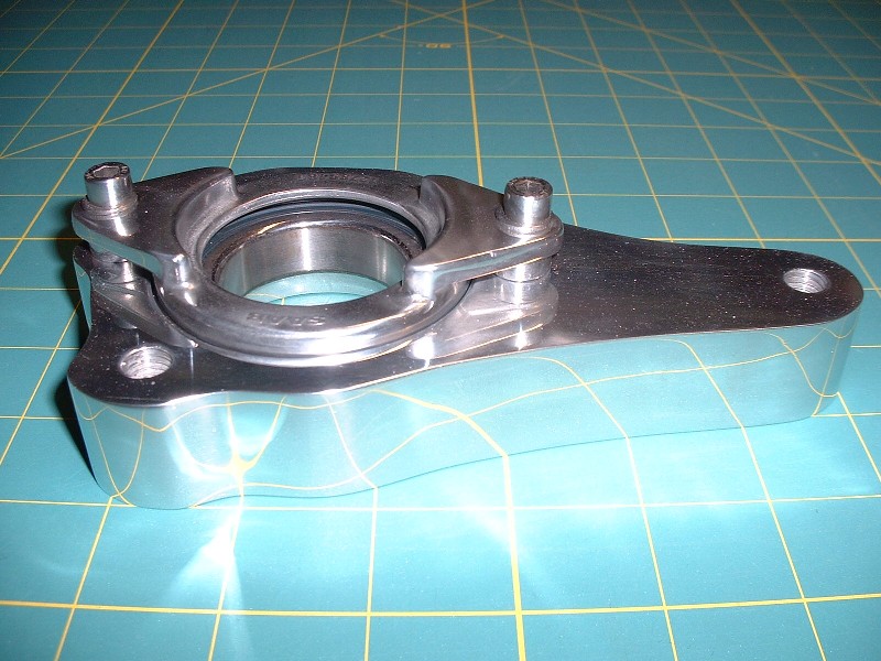
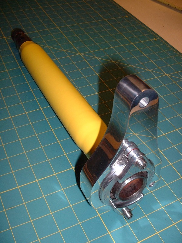
Back on track here… 6061 aluminum is amazing to polish, as I recently found out. I spent about two hours with some 220 grit followed up with some 320 grit and then hit the polisher with the bearing housing. I think I accidentally stumbled on Romulan cloaking technology! Check it out:
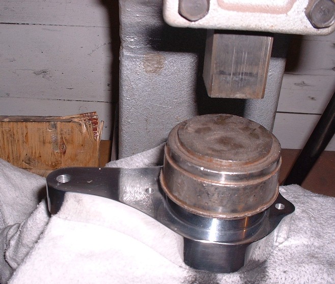
I didn’t want to get sanding and polishing grit in the bearing itself, so I did all the dirty work before pressing it into the housing. Here’s my faithful old arbor press squeezing that sucker into its new home. I apologize for the glare (then again, no I don’t!).
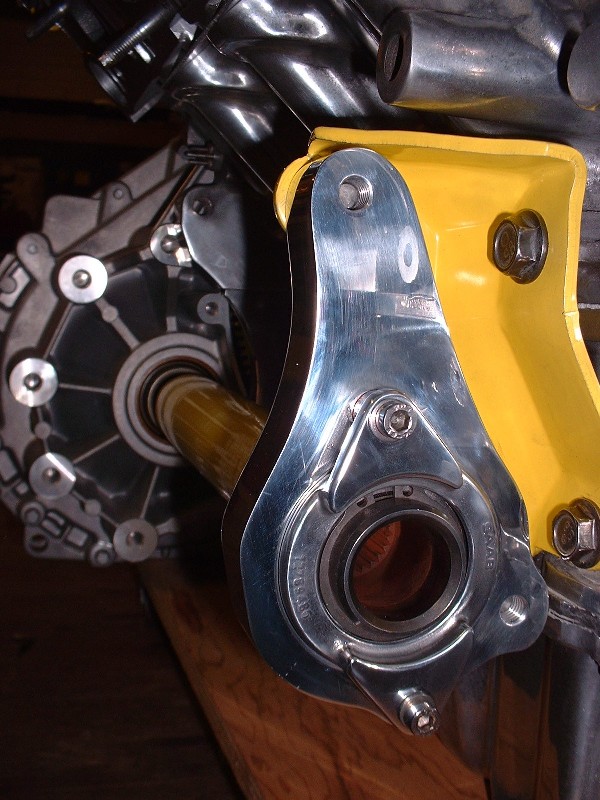
To craft the perfect bearing housing, I would have had to use an aluminum plate 1-3/16” thick. This would’ve given enough backspacing on the housing to mate up with the yellow bracket, and enough material on the front face of the housing for the bearing to be recessed ¼” into the front face. The ¼” is needed so that the countersunk bearing retainer sits correctly. Since the only available plate at the time was 1” thick I decided to make the housing full thickness on the back-side where it meets up with the yellow bracket, which meant that the front face would be 3/16” shallower than ideal. The only impact of having done this is that I’d need some 3/16” spacers for the bearing retainer, so I quickly fabricated some up from some spare 5/8” diameter aluminum rod I had laying around.
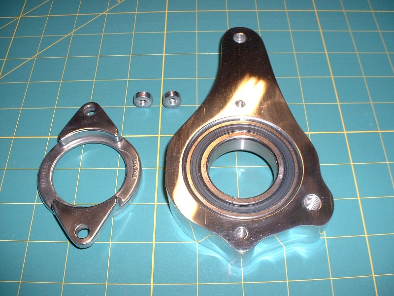
And since a picture says a thousand words, here’s where the spacers needed to go to make everything hunky-dorey. (I’ve only partly de-cloaked the housing so you can see what’s going on.)
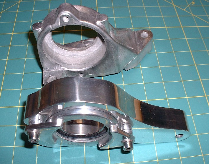
Here’s the old Saturn Ion bearing housing and my new one, side by side for comparison. I’m glad I didn’t bother trying to polish all the nooks and crannies on the Ion mount, I’d probably still be at it! It’s probably only made of white metal anyways and would have corroded within a couple months.
I roughened up the powder coating on the jackshaft with a Scotchbrite pad, undercoated it with some white paint, then hit it up with John Deere yellow. Once it was dry, I was able to press it into the bearing.
With done, all that was left was to install the assembly into the transmission and bolt it up to the old Caddy transmission snout bracket.
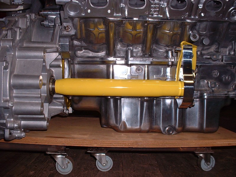
Initially, I found that the axle didn’t turn very freely, so I removed it and elongated the holes in the yellow bracket by about 1/8” closer towards the engine and tried it again. After a bit of adjustment up and down and sideways, I managed to find the sweet spot and tightened it up. In this shot, you can see why the through-hole in the back of the housing needs to be a certain diameter. It has to be large enough to insert a pair of snap ring pliers to remove the ring if necessary.
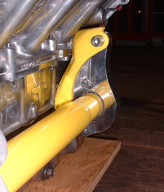
Finally, here’s the view from the wheel-side of things.
Now it’s time to get busy field-stripping the dilithium reactor, realigning the power tunnel, and fixing the impulse drive on the warp core. Geordi LaForge.... uhhh... I mean... Bloozberry out.

|
|
|
|
GT-X
|
NOV 27, 10:27 PM
|
|
Amazing work, keep it up!
~Tyler------------------
| quote | | Is it solipsistic in here, or is it just me? |
|
|
|
|
|
drive135mph
|
NOV 29, 11:34 PM
|
|
|
I love your attention to detail
|
|
|
|