
 
     |
| Blooze Own: An F355 Six Speed N* Build Thread (Page 27/126) |

|
bubbajoexxx
|
NOV 08, 05:44 PM
|
|
(arrow A). I’ll have to replace that bolt with a pan-head bolt to get the necessary clearance… right now it’s touching the belt.
replace that bolt with an allen head cap screw and counter sink the bolt head
|
|
|
|
Bloozberry
|
NOV 11, 08:00 PM
|
|
Thanks Charlie. As for Dratts... I think this car is going to be a fair-weather baby... and we have clean roads in Nova Scotia (well... until harvest time that is.) Bubbajoe, that is a great idea. I'll post an updated photo when I get around to doing just what you said.
And now… for the transmission. Most people reading this thread are well aware of the incredible deals that were to be had starting about a year ago on Pontiac G6 transmissions, but for those tuning in for the first time, here’s a brief summary. In 2006, Pontiac offered a new higher-powered version of the G6 sport sedan called the GTP. The GTP had a 240 horsepower 3.9 L V6 with variable valve timing which came standard with a four-speed automatic transmission, but for no cost, a six-speed manual transmission was available. The transmissions fabricated by GME in Germany are known as the F40 (RPO code MT2) and came with the following gear ratios: 3.77 / 2.04 / 1.32 / 0.95 / 0.76 / 0.62 / Rev 3.54 with an axle ratio of 3.55 which gave a final drive raito (in top gear) of 2.51:1. The torque capacity was officially rated at 295 lbft.
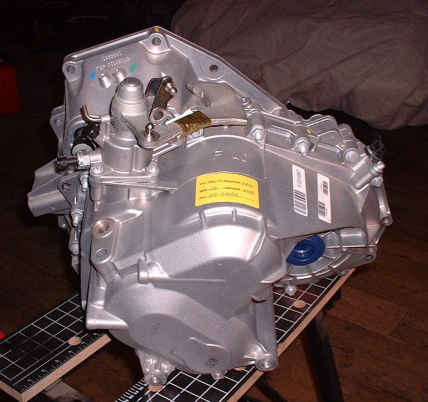
These transmissions however were superseded in 2007 with ones having slightly different ratios and a few improvements to counter noise complaints, resulting in a surplus of F40’s. Sometime in 2008 these surplus transmissions started appearing for retail sale through a number of online sites for approximately $400 - $500, an incredible deal considering they were brand new, and worth between $4000 - $5000 in 2007. I bought mine from a company in Michigan called Schram Auto Parts for a grand total of $666 including shipping, duties and taxes.
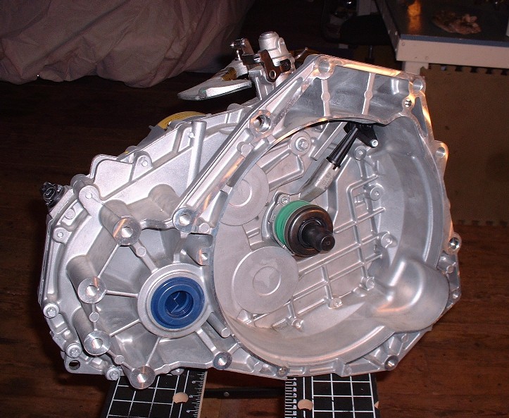
The nice thing about the F40 and the Cadillac Northstar, as many people know, is that they have nearly compatible bellhousing patterns. The major differences are the starter locations, a slight interference with the Northstar’s rear mounted coolant manifold, and one bolt hole that doesn’t line up with the rest. The F40 and the Northstar have been mated successfully by several people here on PFF and the next couple posts will really only be duplicating what has already been done before. The difference is that I hope to provide a bit more detail on how to go about doing the necessary mods.
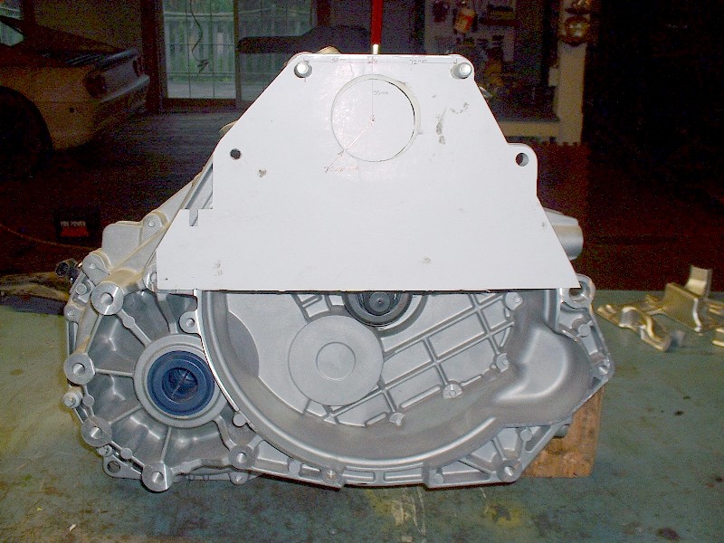
So then, the first thing that needed to be done was to sit down with a ruler, a compass, and some cardboard to make a template of the F40’s bellhousing flange. With a mock-up traced out, and using the top two mounting holes, I then transferred the template to the rear of the Northstar. That’s when I first noticed the interference with the water log and carefully trimmed out the triangular piece to the left of the picture. Then I measured the location of the starter snout on the engine in relation to the top two bolt holes and traced it onto the template so I could transfer the starter location back to the F40.
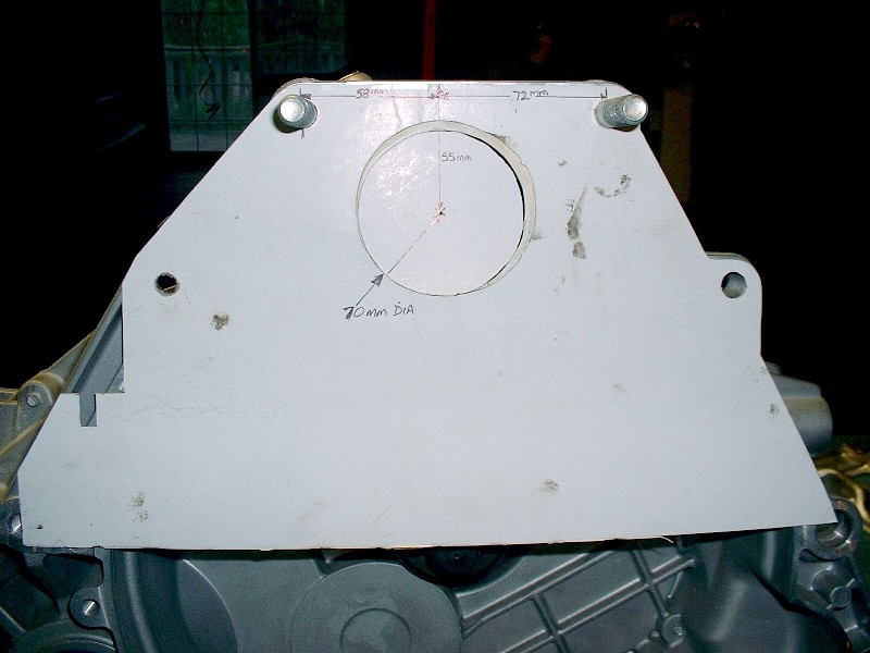
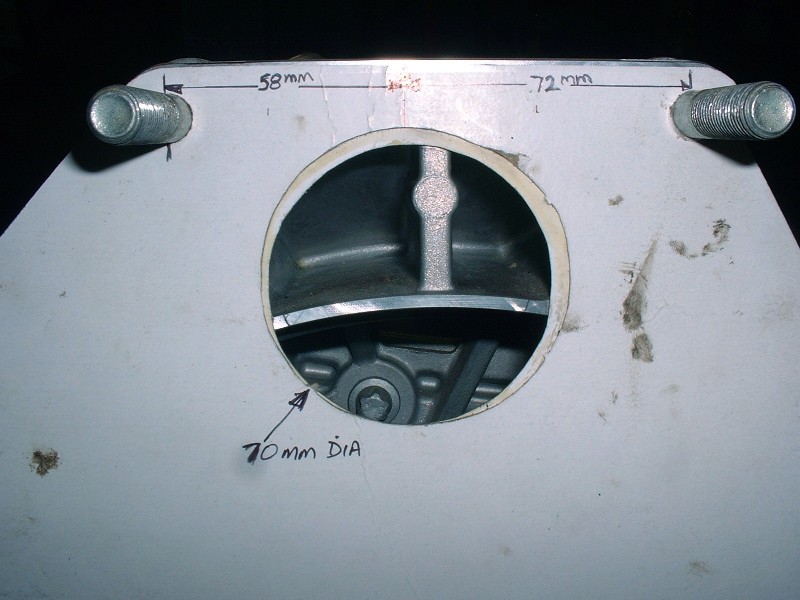
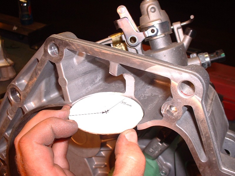
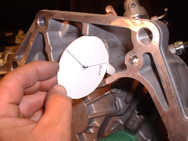
Here are the critical dimensions for anyone doing this in the future. Basically locate the center of starter hole 58mm to the right of the top left bolt as viewed from the bellhousing side of the transmission. Then, drop 55mm down at 90* from the top edge of the bellhousing to locate the center of the starter. Use that point to draw a 70mm diameter circle (35mm radius), which is just large enough to clear the diameter of the starter snout.
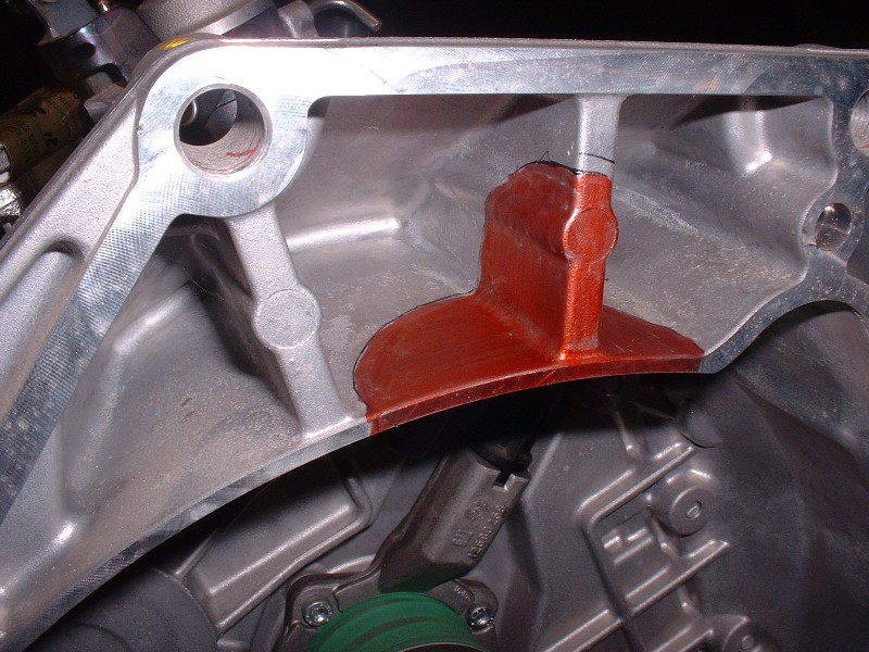
Use an exacto knife or something similar to cut out the hole since you’ll need to keep the circle for later. Next, test fit the template on the engine to be sure the starter hole is properly located. Once satisfied I had the hole in the right place (if you look carefully, it took me two tries!), I relocated the template back on the transmission using the two top bolts, and colored the edges of the webs that I could see through the starter hole using a red marker. Notice that the hole isn’t centered on the vertical web of the transmission.
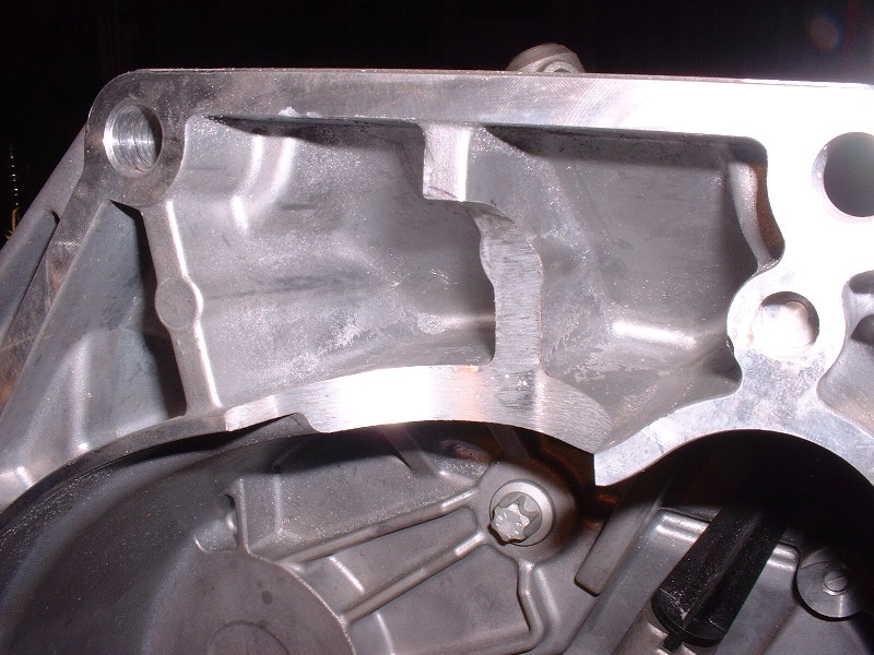
Then, to locate the depth of the starter notch on the horizontal web, I took the 70mm round hole I cut out earlier, drew a line through the center of it, and used it to trace a half circle under the horizontal web, lining it up on the red marks I had made earlier. Finally, to get the right depth of the notch on the vertical web, I just measured 35mm from the machined edge back along the intersection of the two webs and then eyeballed the quarter round shape using that mark and the one made earlier on the vertical web using the template. If you can’t follow what I just wrote, then this picture should help:
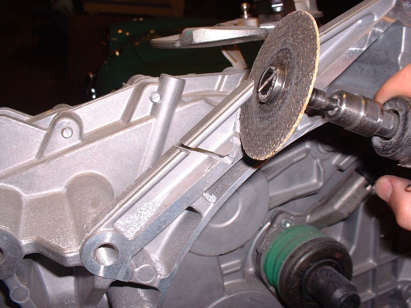
The next step was what I thought would be the easy part: cuting out the notch. Ha! That aluminium is hard! I first started with a fluted grinding bit on my die grinder and it worked OK for the first bit but then galled up with semi-molten aluminium.
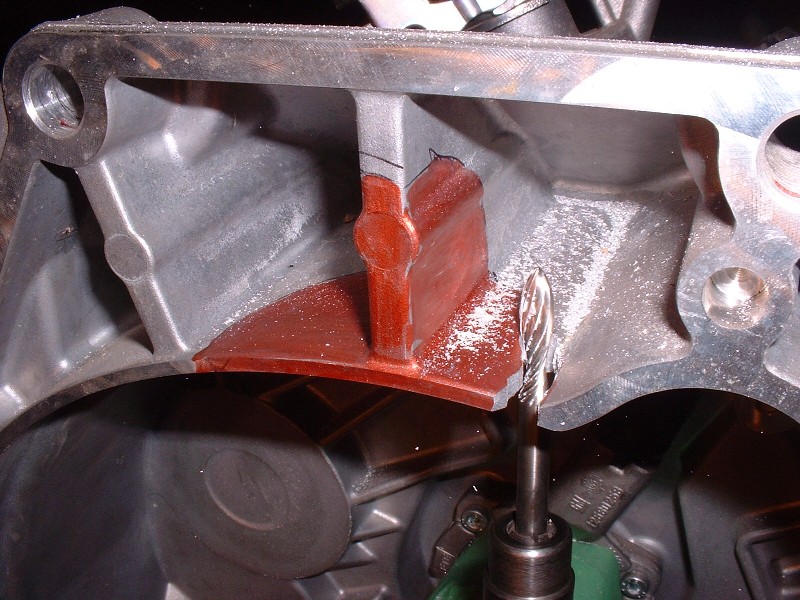
Next, I tried what I call a Zippy-tool… it’s basically a dremel on steroids that uses special bits that look sort of like drill bits, except they’re made to be used like a router. That thing made the going a little easier, but it still took me close to 1.5 hours to do it right, and not have it looking like some butcher with a sawzall did it. The most difficult part was the vertical web since there isn’t a lot of room to manouvre.
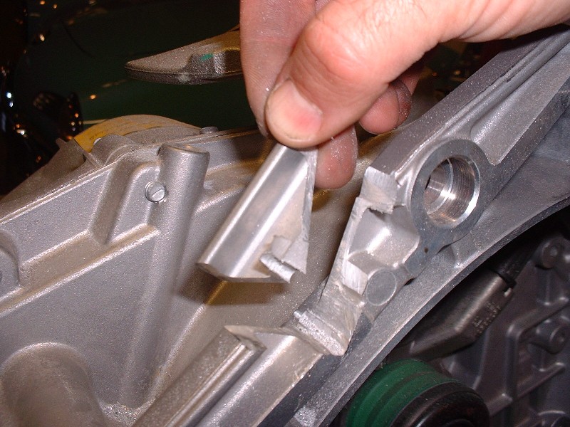
Here are the parts (finally) out of the way:
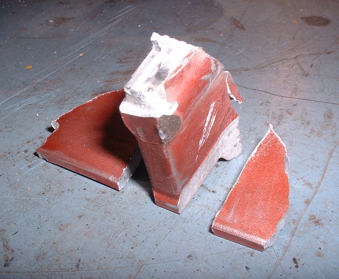
And here I am test fitting the 70mm circle to be certain I cut enough material away both horizontally and vertically.
Lastly, here is the nicely finished notch once I was satisfied the profile was right and after I cleaned the edges with a 2” sanding drum.
 [This message has been edited by Bloozberry (edited 11-11-2010).]
|
|
|
|
dratts
|
NOV 11, 09:30 PM
|
|
|
I've seen getrags modified the same way for a N*. Needless to say, this is the neatest job I;ve seen on this modification. Nice job!
|
|
|
|
Bloozberry
|
NOV 14, 10:03 PM
|
|
(Just a quick side note here: for those that are interested, I edited an earlier post on this page by adding a photo of how I resolved the interference between the serpentine belt and the head of a bolt.)
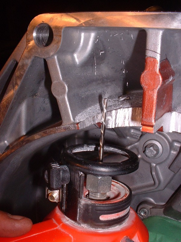
Next on the “to-do” list was to cut the triangular wedge out of the bellhousing to clear the water manifold at the back of the engine. I simply traced the outline from the template I made earlier onto the bellhousing. Then, to make a nicer radius at the corner where the two cuts meet, I first drilled a hole. I used a cutoff wheel on my die grinder to make the cuts and it went fairly well:
Here’s the little piece once it was cut out. I later used a file and smoothed out the freshly cut surfaces.
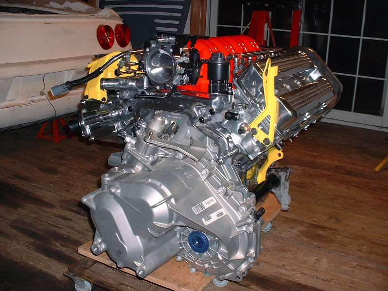
With those two modifications done, it was finally time to test-fit the transmission to the engine! The F40 weighs 123.5 lbs wet, according to literature… (they’re only shipped with a small amount of oil in them) so they’re easy enough for one person to handle. When I slid it on, the two alignment dowels on the engine gave me a little grief, but apart from that, it went on with only a small hitch. There’s an engine sensor of some kind (not sure what it’s for yet) on the side of the engine block, in-line with the triangular cut-out on the transmission. The sensor doesn’t interfere, but a spring-clip holding the sensor wraps around to the bellhousing face that gets in the way. For now, I just bent the clip away. Here’s the assembly.
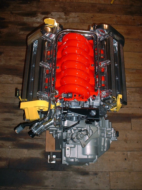
And a top view. It’s amazing how much of the transmission disappears under the water manifold before finally mating up with the bellhousing face of the block. My next big decision is what to do to refinish the transmission. I’m not polishing it, that’s for sure, and I don’t feel like taking it apart to have it powder coated, so painting it to keep it looking fresh might be the solution… but I’m undecided.
Here’s a close up of the area on the transmission where the triangular notch was cut out to clear the water log. I purposefully made it as tight as possible to avoid the appearance of an aftermarket mod.
Those eagle-eyed among you may have noticed an extra piece of hardware in one of the pictures above. Well here it is:
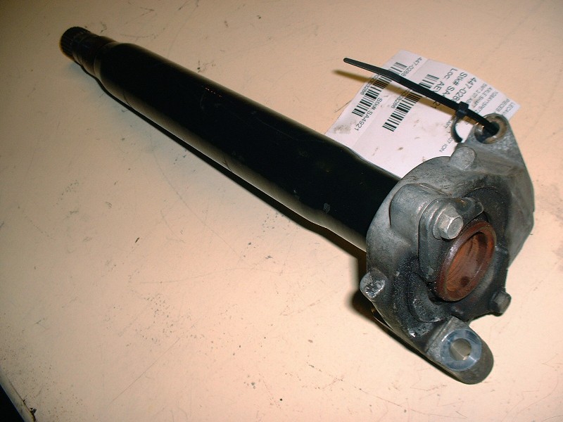
When I travelled up to Ottawa for the Roger Waters concert a month ago, I took a detour up to Ste Sophie in the Quebec Laurentians. The only used parts dealer on Car-Part.com in all of Eastern Canada that listed a Saturn Ion / Chevy Cobalt SS jackshaft was up there. This one is actually from a 2007 Ion. Not including the cost of the detour, it was $108 after taxes.
Zac88GT came up with an ingenious way to mount the jackshaft bearing carrier to the Northstar here about 2/3 of the way down the page: www.fiero.nl/forum/Archives...100421-2-086234.html but I decided to do things a little differently. Over the next couple posts I’ll cover what I’m doing, as well as the mods to be able to use as many of the bellhousing bolt holes as possible since some of them aren’t threaded and one doesn’t line up.
|
|
|
|
War Hammer
|
NOV 15, 01:00 AM
|
|
|
|
|
doublec4
|
NOV 15, 01:01 AM
|
|
Very nice!
Chrome paint the transmission and it should match fairly well I'd think.
|
|
|
|
aeffertz
|
NOV 15, 08:54 PM
|
|
|
I think the silver on the trans. looks good as is. What if you painted it with that same, glossy red?
|
|
|
|
Nashco
|
NOV 18, 12:26 PM
|
|
I vote for leaving the trans as is. If it isn't seeing salt (or much moisture, for that matter) it won't get funky and should be fairly easy to keep clean.
Bryce
|
|
|
|
Bloozberry
|
NOV 19, 10:26 PM
|
|
With the transmission-to-engine installation mocked up, there’s tons of measurements to take for future reference to help determine where on the cradle the powertrain can potentially be installed. The most important one is fore and aft axle alignment in relation to the hubs. Unlike universal joints, CV joints don’t mind running at angles but even so, the idea of placing the transmission output shafts in line with the wheel bearings is to prevent the axle from becoming the limiting factor for suspension travel. With that in mind, I needed to get the jackshaft rigged up so that I would have a much better ability to measure and line up the transmission output shaft in relation to the passenger side hub, which is a long, long way away from the transmission!
I decided to use a jackshaft primarily because I am widening the track width of the car by 3” on each side. Without a jackshaft, this would have meant trying to find a passenger side axle that is about 4” longer than the stock Fiero axle. (The extra inch comes into play because the F40 differential is also shifted 1” further to the driver’s side of the car in relation to the bellhousing surface.) I don’t think I would’ve been able to find any such beast without expensive custom fabrication. Using the jackshaft, it will be easy to find an axle with one set of splines already matched to my needs, and the most it will need is shortening and splines machined on the other end. This will be considerably cheaper than buying a totally new custom-made extra long axle. There are other benefits too.
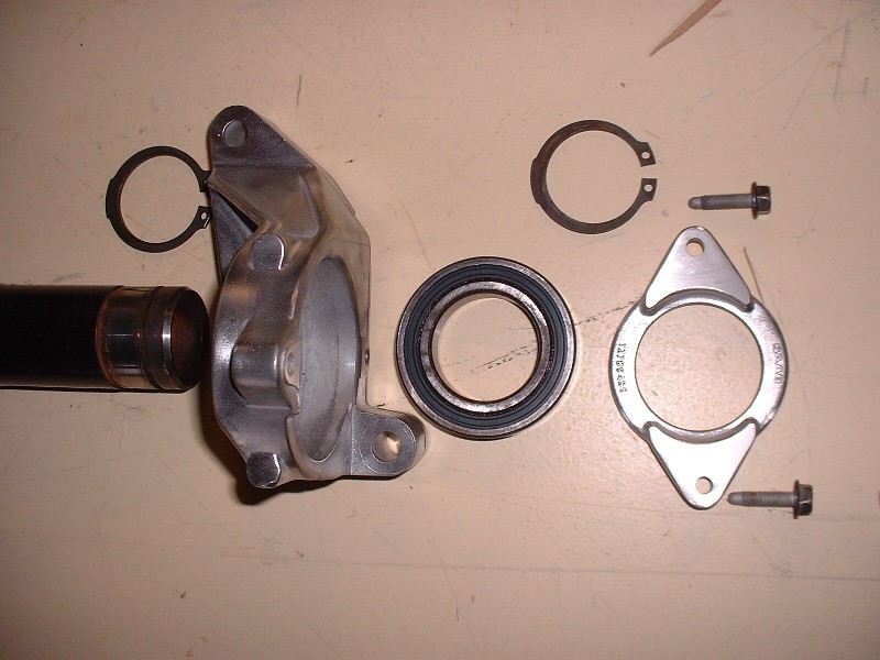
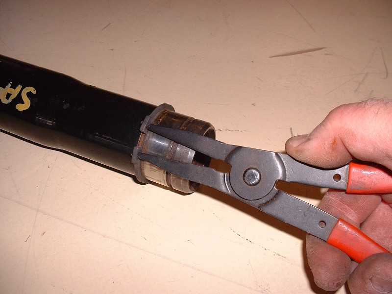
Here’s the 2007 Saturn Ion jackshaft cleaned up and disassembled. It’s really quite easy to take apart, all you need is a pair of good snap ring pliers and an arbor press to get the bearing out of the carrier, and the bearing off the axle. The bearing is located in the housing on the left hand side of the picture by an integral backstop machined into the housing. To keep the bearing from walking out of the housing on the right side, there’s a ring (the piece to the extreme right of the picutre) that bolts to the housing and sandwiches the bearing against the backstop. (Notice these are SAAB parts!)
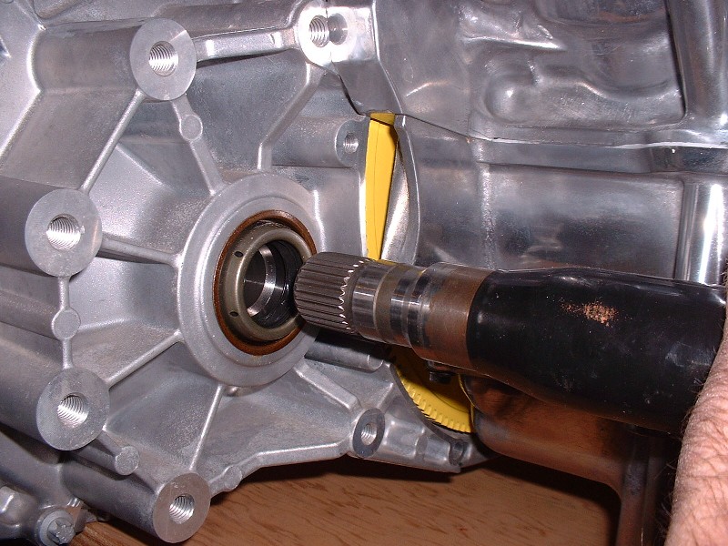
I needed to visualize where the jackshaft bearing would be located and what bosses on the engine might be available to hold it in place, since the Ion bearing housing wasn’t lining up with anything. I temporarily installed the jackshaft into the F40. Unlike the Fiero transmissions, there aren’t any snap rings that hold the jackshaft in the transmission, rather, this function is performed by the bearing housing.
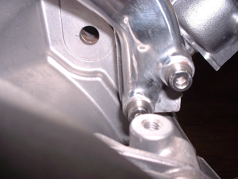
After lots of eyeballing, there just didn’t seem to be a good way to fabricate and mount a custom housing because the bearing fell too close to the bosses on the block to make good use of them. Then in a fluke, I installed the OEM automatic transmission bracket on the engine and the light went on.
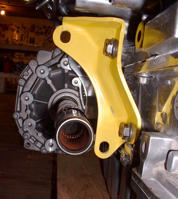
It still took a little figuring out, but the OEM bracket afforded a nice strong base from which to work with. It also placed the mounting holes for any new bearing housing design in a much more favorable orientation to work with. (BTW, the dullness of the block is due to me having sprayed it with WD40 to keep it from oxidizing.)
The next challenge was to find a way to measure the distance from the holes in the yellow bracket to the centerline of the of the axle in free space. After some thought, I fabricated a preliminary jig out of ¾” plywood that would hold the bearing and that I could then install on the axle. I cut the wooden jig to a 4-1/8” outside diameter because I happened to have a hole saw that big and because it left enough material to be able to pick up the lower hole on the yellow bracket, and still clear the block. It could have been any shape but the hole saw was handy.
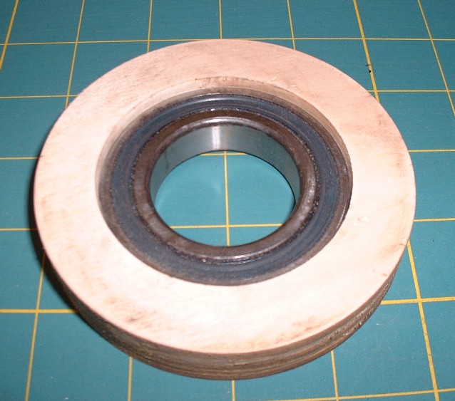
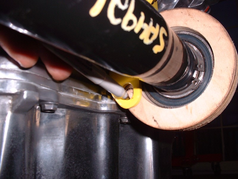
To make sure I got the bearing at the right depth on the axle, I installed the inboard snap ring, and then pressed the bearing and preliminary jig into place.
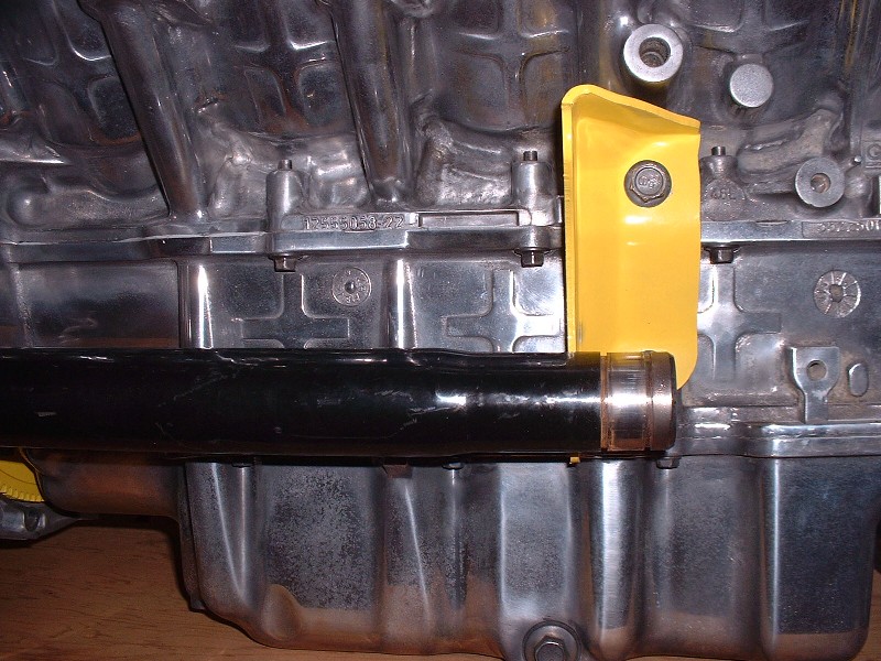
Once the jig was securely butted up against the yellow bracket, I double checked that the jackshaft was also inserted the proper depth into the transmission. To do this, I simply made sure the mark on the shaft from the original car's output seal was more or less in line with the F40's output seal. Then, I traced the location of the lower hole onto the jig from the back side of the yellow bracket.
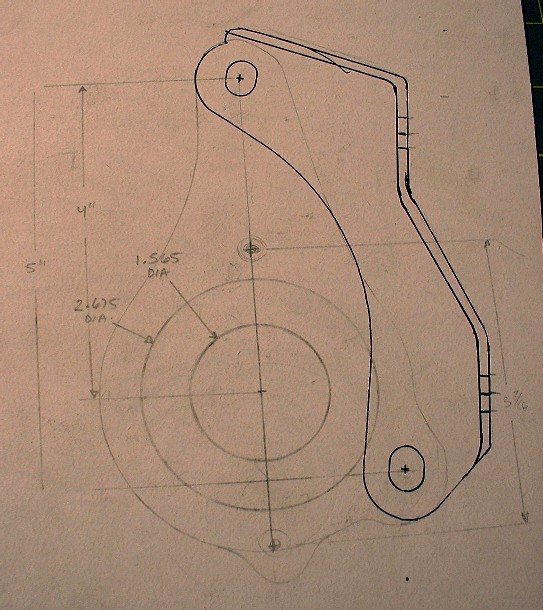
This then gave me a fairly precise ability to measure where the mounting hole was in relation to the center of the axle, and it allowed me to make a few measurements to determine how thick the final housing would have to be to reach the bracket on the inboard side, and yet still locate the bearing in the correct axial position on the jackshaft. With that information, I was able to work up a shape for a new bearing housing that would mate to the OEM transmission bracket. Here is the preliminary drawing I made.
|
|
|
|
cptsnoopy
|
NOV 19, 11:39 PM
|
|
If it helps, I found that using the stock fore/aft location on the cradle worked fine for mounting the N*. Not sure if you still have the ability to pull that from your setup or not.
Charlie

|
|
|
|