
 
     |
| Blooze Own: An F355 Six Speed N* Build Thread (Page 26/126) |

|
Erik
|
NOV 02, 01:39 AM
|
|
|
. [This message has been edited by Erik (edited 11-03-2010).]
|
|
|
|
Erik
|
NOV 02, 01:46 AM
|
|
|
That"s badass really cleans up the look! I might just do that on my ITB setup thanks for the great idea. Your engine is the best looking one on the forum.
|
|

|
bowrapennocks
|
NOV 02, 09:18 AM
|
|
A most incredible build. Keep up the great work. I just bought an F40 6SP and just started planning my swap. I have decided on which engine yet. I look forward to how you address clutch/pp, flywheel and axles. Keep going I just can't wait.
Jim
|
|
|
|
aeffertz
|
NOV 02, 02:39 PM
|
|
That injector wiring is very impressive! 
|
|
|
|
BlackGT Codde
|
NOV 05, 07:21 PM
|
|
you my good friend are a REAL technician.
the entire industry has gone the route of parts changing. i think there can still be a market for real mechanic/tech work and doing it right.
following and extremely interested. love the work.
i work at a gm dealer and have never seen anyone even try to use ingenuity like yours.
best of luck to you.
oh and gm reccomends mobil 1 in all the updated northstars with the 305hp rating... ever notice that?------------------

1985 gt notchie auto (pic)| 3800 SFI N/A coming soon
1986 se notchie standard 4spd | 5.3 vortec soon
|
|
|
|
Custom2M4
|
NOV 06, 10:02 PM
|
|
| quote | Originally posted by cptsnoopy:
Charlie
 |
|
This is how I ran my belt, but I ran it under the idler pully, not over it, without a tensioner.
|
|
|
|
neverendingproject
|
NOV 07, 06:06 AM
|
|
|
I love what you've done cleaning up the engine and making it truly show quality. The wiring looks great, keep up the good work. ------------------
Alan Frazier
'84 2m4 Northstar 5 speed
'84 3800SCII sold
'86 GT-'92 3.4 TDC 5 speed(sold)
|
|
|
|
Bloozberry
|
NOV 07, 08:25 PM
|
|
| quote | Originally posted by Erik:
Your engine is the best looking one on the forum. |
|
I think most people would agree that your Northstar with the ITB’s is going to be the best looking engine on Pennocks! That thing just screams exotica.
| quote | Originally posted by bowrapennocks:
I look forward to how you address clutch/pp, flywheel and axles. Keep going I just can't wait. |
|
This is my last post on accessories and I’ll move onto the transmission and axles next.
| quote | Originally posted by BlackGT Codde:
gm reccomends mobil 1 in all the updated northstars |
|
Thanks for the compliments and for the tip. I was planning on using synthetic oil in this engine after the initial break-in.
As for aeffertz and neverendingproject (NEP for short!), I appreciate your kind words. For Custom2M4, read on... I'd like to know what belt you used.
So then, just to finish off last week’s series of pictures, here’s how I terminated the injector harness wires sticking out of the stainless tube. I had originally thought I’d be able to unplug the connector pins from the back of the connector and fiche them along with the wires through the tube, but there just wasn’t enough room. I made a quick schematic before cutting it off knowing that I’d be in for an hour or so of splicing and soldering it back on the loose wires.
With that done, I waited for the next nice day (it’s been raining for a week now) before heading out to one of the local junkyards in search of a 3.5” idler pulley with grooves to replace the Caddy smooth idler. I think I looked under the hood of every car on the lot before finally finding a ’95 Ford Contour with a 16 valve Zetek engine that had just what I was looking for. The pulley came off of the Contour’s tensioner, not to be confused with the Contour’s idler, which was smooth.
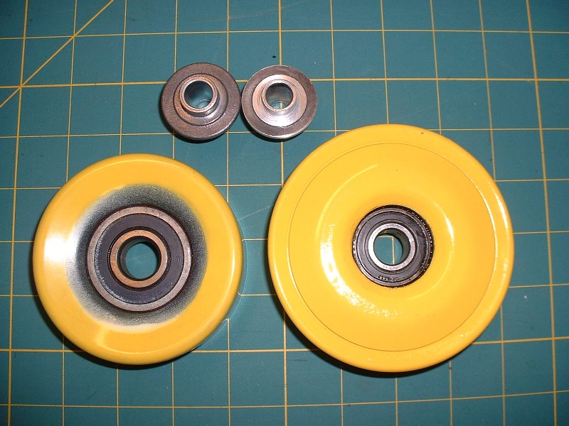
It was in great shape but clearly the wrong color so once I got it home, I pressed the center bearing out of it, bead-blasted, primed, and painted the pulley. Here’s the Caddy idler on the left and the Ford is on the right.
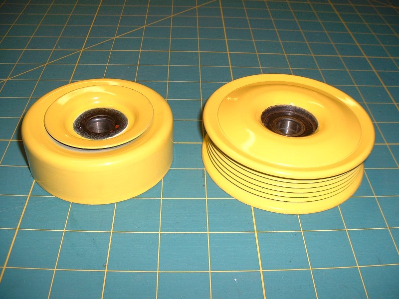
The two pulleys are remarkably similar dimensionally except that the Contour pulley has a much smaller bearing, both ID and OD. The photo below shows the Contour pulley and the Caddy mounting bolt and spacer. The spacer locates the pulley the correct distance away from the block to line up the grooves with the other pulleys. The problem is that the Contour pulley won’t fit on the Caddy bolt and spacer because the Contour’s bearing ID is too small.
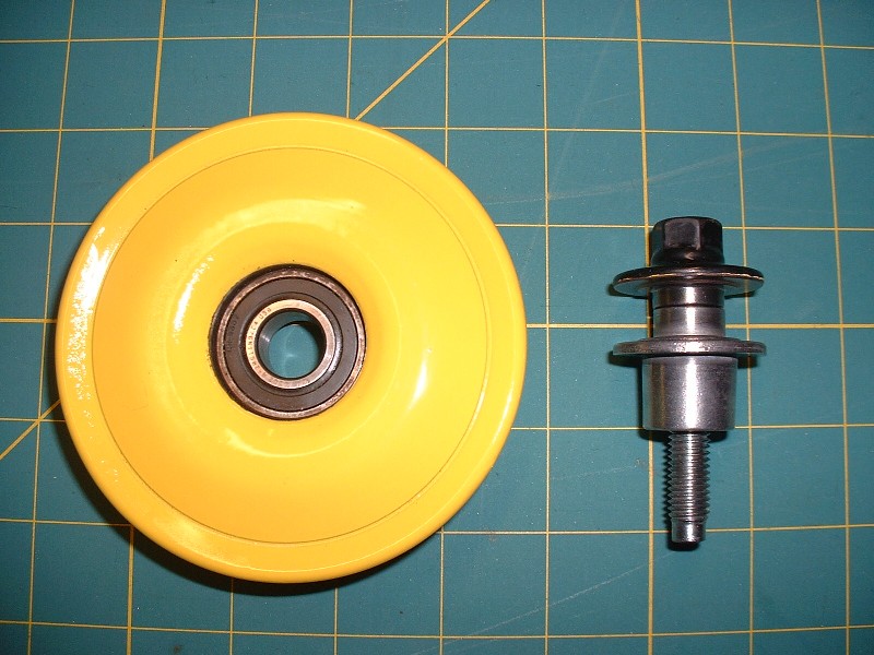
To correct this minor problem, I used the poor-man’s lathe and machined the collars on the Caddy bolt and spacer down from 0.662” to 0.590”, which made a nice fit inside the Contour’s bearing.
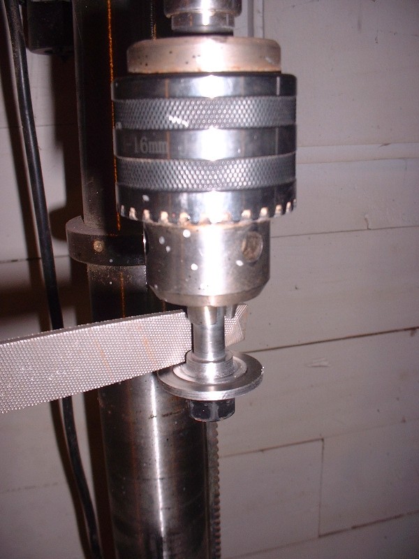
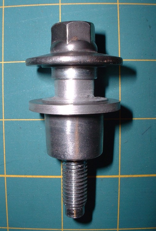
The next issue was the diameter of the Caddy bolt and spacer’s integral washers. They were too big and when installed, contacted the part of the pulley that needed to rotate, so I chucked them up in my drill press again and machined them down from 1.420” to 1.340”. Here’s a picture of the two pieces where only the spacer (the lower part) is machined down in both areas as compared to the bolt which is still the original size:
Here’s another view of the discarded Caddy idler on the left with an unmodified spacer from my spare engine above it, and the Ford tensioner pulley on the right with the modified spacer above it. It’s hard to see the differences in the bearing inside diameters but if you look at the spacers carefully, it’s clear. One last tidbit before the Ford pulley would line up properly is that the bearing must be pressed into the pulley so that it’s flush with the back side of the pulley’s center bore. This provides the correct offset.
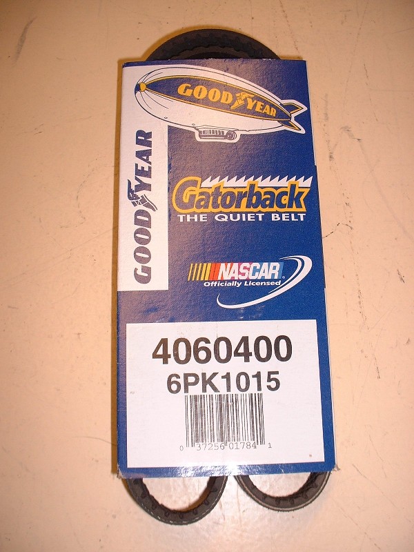
Finding a correctly sized belt was a lot easier than I expected, it just took a lot of sweat to figure out that I actually had the right one. I temporarily installed all of the belt drive system on the engine and carefully measured the planned route of the belt using the original Caddy belt, which is waaaay too long. I calculated that the new belt would need to be an odd-ball 40.5” long... oh great (sigh). I crossed my fingers and called the local auto parts store and luckily they had a six-rib Dayco at exactly 40.5” (part number 5060405). For good measure, I also brought home a Goodyear Gatorback that was 40” (part number 4060400).
After routing the 40.5” belt the way I had originally intended, the tensioner was up against it’s stops (vrtually useless) and the belt wasn’t especially tight. So next I tried the 40” belt and worked like a dog at installing it for what seemed like an hour without any luck… it was just too tight to get on the pulleys no matter how I tried. It’s hard to believe that a half inch one way or the other could result in too much slack or not enough. So then I tried Custom2M4’s idea of reverting back to the stock Caddy smooth idler from my spare engine and running the belt under the idler and ditching the tensioner (I really really wanted to use the tensioner after having spent countless hours polishing it though!) But, neither belt was long enough to reach in that configuration either. I don’t know what belt Custom2M4 used, but the 40.5” was too short and the next size up (46” I believe) was clearly going to be too long.
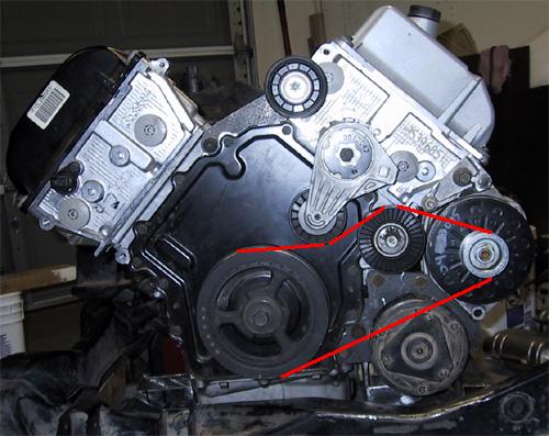
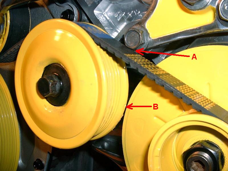
Finally, I retried my original idea with the 40” belt, only this time I changed the order which I installed things, and it worked. Here’s the trick for anyone duplicating my configuration: First, have only the crank pulley and alternator pulley installed, and slip the belt on those two. Next, slide the modified Caddy idler bolt part way through the Contour pulley and screw the spacer partly on the backside. Then place the idler pulley under the belt and reef up on it as hard as you can to align the bolt with the hole on the block, while a second person screws the bolt. At this point the belt is quite tight and it’s no wonder there wasn’t enough slack to pull the belt over the ridges on the idler when I tried it the first time with the idler already installed. Lastly, to get the tensioner on, there’s only one way. It’s held in place by one bolt but it has an integral pin on the backside that mates with a hole in the block to keep it from spinning on the one bolt. To get the tensioner on, don’t stick the pin in the hole and try to lever the bolt to line up with it’s hole, instead, screw the center bolt into the block part way first. Then, using a ½” ratchet wrench in the square hole on the tensioner arm, rotate the entire tensioner about the center bolt’s axis until the pin lines up with it’s mating hole in the block. At this point the tensioner will be under a lot of tension so you may need someone else to finish tightening the center bolt, drawing the pin into it’s hole at the same time. Here’s the final belt routing:

The Contour’s pulley comes within 1/8” of the Caddy alternator fan (arrow B), but it should be enough clearance not to make contact. The only other issue is with one of the bolts that hold the dog bone bracket to the block (arrow A). I’ll have to replace that bolt with a pan-head bolt to get the necessary clearance… right now it’s touching the belt.
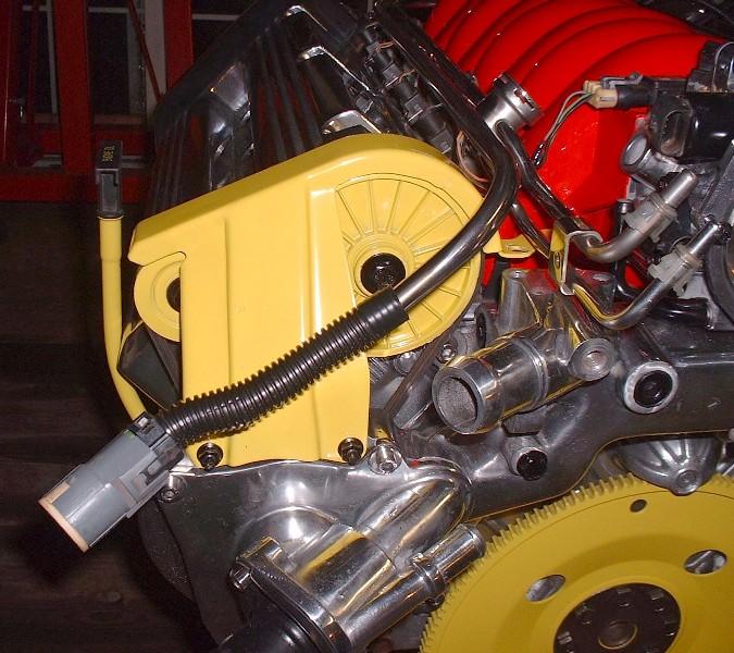
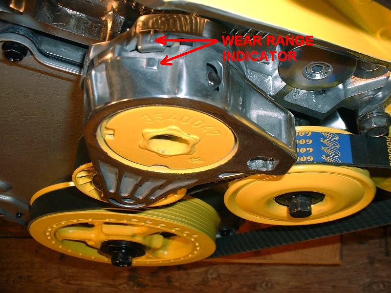
Finally, once I had cycled the tensioner arm a couple times using a ratchet in the square hole, the tensioner settled into a nice spot exactly within the range it was designed to operate in. The picture below shows the little pointer on the stationary part of the tensioner hub pointing at the small raised square that indicates the center of the tensioner arm’s travel. And what you don’t see, is the smile on my face knowing that the engine is basically done .
EDITED TO ADD:
To solve the interefence between the belt and one of the bolts pictured above, I considered advice from Bubbajoe to buy an allen-keyed socket head bolt and countersink it into the aluminium dogbone mount. Once I had a closer look though, there simply wasn't enough material thickness to the mount to do this. Instead, I used a low profile panhead bolt and gained the needed clearance.
 [This message has been edited by Bloozberry (edited 11-14-2010).]
|
|
|
|
cptsnoopy
|
NOV 08, 01:21 AM
|
|
Just freakin gorgeous! Thanks for sharing.
Charlie
|
|
|
|
dratts
|
NOV 08, 10:08 AM
|
|
|
Are you going to put that engine in your car where it will get all dirty?
|
|
|
|