
 
     |
| Blooze Own: An F355 Six Speed N* Build Thread (Page 25/126) |

|
cptsnoopy
|
OCT 23, 12:15 AM
|
|
Interesting, my Aurora fuel rail was mostly straight. Straight enough that I decided to leave the stock quick connect fittings on and run it as is. I bought it and the pr new so I did not have to worry about it being gummed up. The regulators should be nearly, if not, the same. I know that Russ found some slight difference in the ones he had and my new one but not enough for me to be concerned. The engine looks awesome. I did not think about the idler being on the other side of the belt... When I bought my PS delete pulley I just went to the local auto parts store and bought a Dayco brand. Hopefully it'll last a while. Good luck getting the "perfect" length belt. 
Charlie

|
|
|
|
Bloozberry
|
NOV 01, 03:34 PM
|
|
OK, it's been a week since I last posted up some progress, so let's play a game. Can anyone spot what I've been up to?
 [This message has been edited by Bloozberry (edited 11-01-2010).]
|
|

|
topcat
|
NOV 01, 03:53 PM
|
|
I see you got the fuel rail polished and installed.
Looks good -
|
|
|
|
Bloozberry
|
NOV 01, 04:49 PM
|
|
|
True... but that's not it.
|
|
|
|
FieroDev
|
NOV 01, 05:12 PM
|
|
|
|
|
Bloozberry
|
NOV 01, 05:37 PM
|
|
|
You'll have to be more specific.
|
|
|
|
topcat
|
NOV 01, 05:47 PM
|
|
|
I saw the labled wires coming from the fuel log area, but I am not familiar with the N* engine, so I am clueless what those wires are for.
|
|
|
|
Erik
|
NOV 01, 05:50 PM
|
|
|
the injector wiring is inside tubing
|
|
|
|
Jefrysuko
|
NOV 01, 07:34 PM
|
|
|
And you installed the dipstick!
|
|
|
|
Bloozberry
|
NOV 01, 07:38 PM
|
|
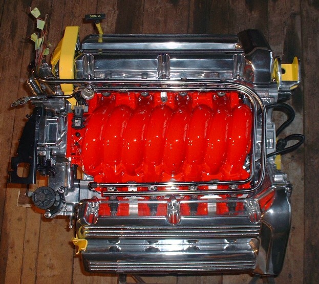
Bingo, Jefrysuko figured it out! Just kidding... Erik was right. I kinda figured it would take someone with a Northstar to spot the difference. I wanted to finish off the "cleaned-up" manifold look by hiding the wire harness to the injectors. My first thoughts were to run them underneath the intake in the valley between the cylinders, but that would've meant having to drill additional holes in the plastic somewhere to get them on the right side of the manifold again. The space is there to do it, but I wasn't keen on removing some of the webbing under the manifold to accomplish it that way.
So, on to door number 2: stainless tubing. I figured by mimicking the contour of the fuel rail with a second stainless tube, it would fool most people into thinking it's part of the stock fuel system, like a return line or something. The fuel rail is 1/2" OD, so I didn't want to go any larger than that if possible, so I played around with some carbon steel tubing just to see if I could bend it with the right radii, and if all 19 wires would be able to fit into that tight little tunnel. That's where the first hurdle was. The steel tubing had 3/32" wall thickness and was just too tight to fit them all in. After about a week's worth of looking everywhere (on-line, locally, nationally, etc) I finally found a source for some stainless tubing 1/2" OD with 0.065" wall thickness for about $1.25 a foot! Considering that the only other places I could find 1/2" OD stainless was at a medical supplies store for over $170 for a 4' length, I figure I lucked-in.
So the first step was to bend it and mock up some stainless legs to hold it at the right height on the manifold. Interstingly, the fuel rail doesn't have two 90* bends in it. It actually is angled along the bottom of the U to follow the angle of the intake runner:
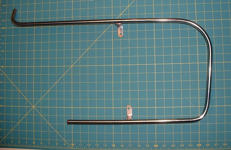
I kind of knew that two legs wouldn't be enough, and was right, so I fabbed up another leg and welded it on to keep the whole thing from teeter-tottering.
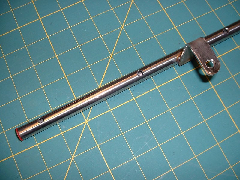
Next, with it temporarily installed on the manifold, I marked where the wires would need to come out of the tube to mate with the injectors themselves, and then drilled, and chamfered the holes to keep the edges from chaffing the insulation.
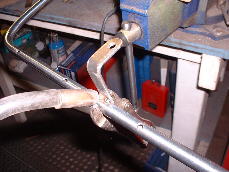
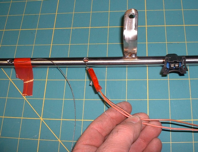
The hardest part was actually threading the wires for the injectors through the tube. At first I thought they'd all just slip inside and everything would be hunky-dorey. Not so. There's enough room inside the tube, but only just enough so the last four wires get really tight. Then I tried fisching them through with extra-tough strings like in the photo below, but there was no way to adequately fasten the end of each pair of injector wires to the string without the string pulling off towards the end. Lastly (and successfully), I threaded one sacrificial spare wire as a fische through each small hole until it emerged from the end of the tube, then soldered each pair of injector wires to it's respective fiche wire to hold it securely, and was finally able to pull each pair through... but not before a lot of silicone spray lube was used up and a lot of swear-words for the last three MAP sensor wires. I then tested each wire end-to-end for continuity just in case I broke any wires internally, and checked each wire to make sure it wasn't shorting to the tube either, but all was good.
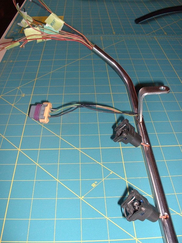
Here's a close up of how the wires and connectors protrude out of the tube. I'll still need to squeeze a dab of silicone sealant into each of the small holes to act as both a sealant and a grommet to protect from the steel edges.
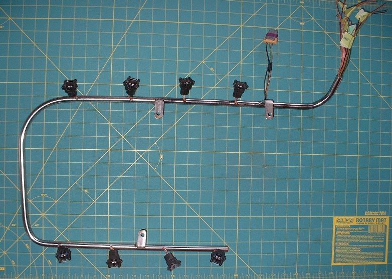
And here's a view of the whole harness tube ready to install on the manifold:
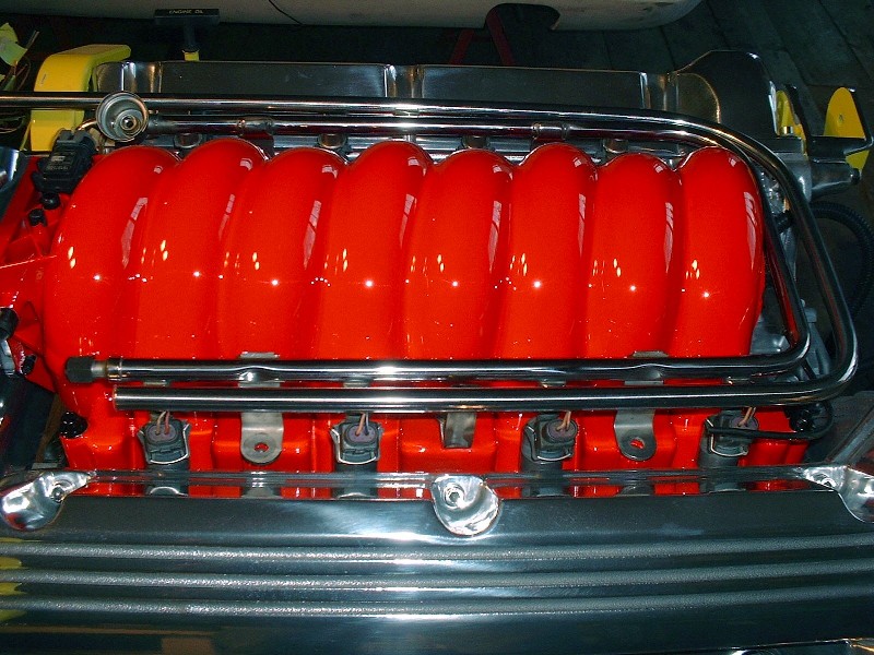
Here's how it mates up with the fuel rail to look like it's an integral part of the design. I opted to weld the little legs of the harness tube in such a way that they pick up different fasteners than the fuel rail does since to do otherwise, it would've been difficult to tighten the fuel rail fasteners with the harness tube in the way.
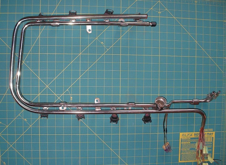
Finally, here's another angle of the whole schemozzle temporarily installed on the manifold as I wait for my good injectors to make their way back to me from a cleaning and rebuilding somewhere in the good ol' US of A. Nice and clean with no wires showing, eh?
|
|
|
|